1
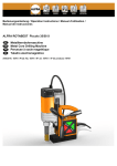
GUNNAR RAPIDO
User Manual
By GUNNAR Weissenberger AG
Weissenberger AG
Staatsstrasse 119
CH-9445 Rebstein
Tel: +41 (071) 775 82 20
Fax: +41 (071) 775 82 29
04.01 ce
Internet: www.gunnar-europe.com
Contents
General information
1
Introduction ....................................................................................................................................... 1
Safety advice...................................................................................................................................... 1
Intended purpose.............................................................................................................................. 2
Liability ............................................................................................................................................... 2
Data protection.................................................................................................................................. 2
Overview
3
Overall view of the RAPIDO, Fig.01.............................................................................................. 3
Panel, Fig.02 ....................................................................................................................................... 4
Z Head, Fig.03.................................................................................................................................... 4
Blade head, Fig.04 ............................................................................................................................. 5
Controller, Fig.05 ............................................................................................................................... 6
Technical Data
7
Space requirements ........................................................................................................................... 7
RAPIDO M ......................................................................................................................... 7
RAPIDO XL........................................................................................................................ 8
Electrical connection......................................................................................................................... 8
PC connection / settings.................................................................................................................. 9
Pneumatic connection ...................................................................................................................... 9
Environment....................................................................................................................................... 9
Cutting data........................................................................................................................................ 9
Installation
10
Installation of Horizontal stand..................................................................................................... 10
Installation of vertical stand.......................................................................................................... 10
Installation of PC table ................................................................................................................... 10
Supplied with Machine................................................................................................................... 10
Accessories...................................................................................................................................... 11
Unpacking ........................................................................................................................................ 11
Installation of the RAPIDO............................................................................................................ 11
Horizontal Installation .................................................................................................... 11
Vertical Installation ......................................................................................................... 12
Connecting up the RAPIDO.......................................................................................... 12
First Installation of the SPT32 Software ...................................................................................... 12
SPT32 Software Update.................................................................................................................. 13
Backup .............................................................................................................................................. 13
Operating the RAPIDO
14
Starting the SPT32 Software .......................................................................................................... 14
Switching off the system................................................................................................................ 14
Insert cardboard .............................................................................................................................. 15
Changing blade................................................................................................................................ 15
GUNNAR RAPIDO User Manual
Contents • i
Machine settings............................................................................................................................. 16
Reading in the basic settings ........................................................................................ 16
Basic settings................................................................................................................... 16
Compressed air setting................................................................................................... 16
Blade depth setting......................................................................................................... 16
Throttle setting................................................................................................................ 16
Servicing
17
Cleaning............................................................................................................................................ 17
General cleaning .............................................................................................................. 17
Cleaning the guide profiles ............................................................................................ 17
Table top........................................................................................................................... 17
Water trap......................................................................................................................................... 17
Replacing parts ................................................................................................................................ 18
Clamping hose................................................................................................................. 18
Blade head........................................................................................................................ 18
Sliding part ....................................................................................................................... 19
Pressure spring................................................................................................................ 19
Fuse................................................................................................................................... 19
Repairs .............................................................................................................................................. 19
Guarantee
20
Guarantee provisions...................................................................................................................... 20
Glossary of terms
21
Index
23
Registry Form................................................................................................................... 25
ii • Contents
GUNNAR RAPIDO User Manual
General information
Introduction
The information contained in this Document corresponds to the latest
developments at the time of publication. Printing errors and mistakes cannot be
excluded.
We reserve the right to make design modifications or to depart from the designs
shown.
Safety advice
Please read the following safety advice before installing, operating, servicing or
repairing the machine.
GUNNAR RAPIDO User Manual
•
The installation, servicing and repair of the machine should be carried out
solely by a GUNNAR trained service engineer.
•
Care should be taken to observe the technical data for the machine, and in
particular the ambient conditions.
•
The machine should be operated by trained personnel. Your GUNNAR
distributor will provide training .
•
Any unauthorized modification or opening of the controller will automatically
render the product guarantee and the safety guarantee invalid.
•
Contact your GUNNAR representative prior to installing accessories.
•
For Security the machine can be served exclusively by one person.
General information • 1
Intended purpose
The RAPIDO has been designed exclusively for cutting cardboard for mounts.
Liability
Weissenberger AG will not assume any product liability in the event of incorrect
handling or use of the Software, the machine or machine components.
Weissenberger AG is additionally not responsible for any loss of data. We
recommend that data be backed up on a regular basis.
Data protection
Weissenberger AG holds all the rights. Neither the machine data nor any of the
Software may be made available to third parties.
2 • General information
GUNNAR RAPIDO User Manual
Overview
Overall view of the RAPIDO, Fig.01
2
8
3
1
9
4
5
RAPIDO
11
6
7
GUNNAR
10
Y+
X+
XY-
1.
Rear cover
7.
Table legs
2.
Y arm
8.
Guide slot
3.
Z head
9.
Panel
4.
Table top
10.
Horizontal stand
5.
Clamps
11.
Protection
6.
Front cover
GUNNAR RAPIDO User Manual
Overview • 3
Panel, Fig.02
5
1
0
I
4
2
6
3
1.
Hose connection
4.
Master switch
2.
Water trap
5.
Machine-on indicator lamp
3.
Pressure reduction for blade head
6.
Emergency stop switch
Z Head, Fig.03
2
1
4
3
5
5
6
9
7
8
11
10
Article
1. Top casing
2. encoder
4 • Overview
number
100026
RE30-2-100
GUNNAR RAPIDO User Manual
3. Compressed air cylinder
17701258
4. Z motor
441.92901
5. Screws for affixing Z head, 4x
DIN912 M5x55
6. Screws for affixing top casing
BN11252 M5x10
7. Screws for lateral fixing of Z head
DIN 912 M4x12 zn
8. Axle for lateral fixing of Z head
100015
9. Z base
100002
10. Blade head
100024
11. Throttle for blade insertion
Blade head, Fig.04
4
2
3
5
1
6
Article
1. Clamping screw
100058
2. Blade holder
100086
3. Pressure spring
WS9711.1203
4. Locking screw
DIN 912 M5x18
5. Depth adjustment screw
DIN913 M5x14
6. Sliding part
GUNNAR RAPIDO User Manual
number
100054
Overview • 5
Controller, Fig.05
12
10
6
1
3
2
5
8
7
9
11
4
13
Label
6 • Overview
description
1. X
Motor
2. Y
Motor
3. Z
Motor
4. IN/OUT
Valves
5.
Nameplate
6. RESET
Push to reset controller
7. INCR
X, Y and Z Digitizer (encoder)
8. COM
Communication (RS232)
9. TEST
Self-test
10. FUSE 6,3A
Main Fuse 230V 6.3A T
11. 115 / 230
Power supply selection switch
12.
Socket for current
13.
Control LED
GUNNAR RAPIDO User Manual
Technical Data
Space requirements
RAPIDO M
The RAPIDO is operated from the front. The preferred cutting table configuration
is in the horizontal position as follows.
Fig. 06
PC
RAPIDO
The best alternative cutting table configuration in the vertical position is as
follows.
GUNNAR RAPIDO User Manual
Technical Data • 7
Fig. 07
PC
RAPIDO
RAPIDO XL
Abb. 06a
PC
135cm / 53 Inch
183 cm / 72 inch
RAPIDO
Electrical connection
The RAPIDO requires a flawless electrical installation with an earth connection
(GND) at 115 or 230 volts before it can be connected.
Main connection
115 V, +13% -13%
230 V, +13% -13%
NB: The power level must not fall short at any circumstances (not even for short
terms).
Power supply voltage (Capture „Connecting up the RAPIDO“ page 12)
230V
115V
Power consumption
8 • Technical Data
max. 1000 VA
GUNNAR RAPIDO User Manual
Frequency
50-60 Hz
PC connection / settings
The RAPIDO should be connected to COM2 if possible, using the RS232 cable
supplied and, if necessary, the RS232 9 pole > 25 pole adapter (also supplied).
The PC must have at least one free COM interface with a FIFO UART 16550
module.
Operating system: Windows 95™ or Windows 98™.
RAM Windows 95™
at least 8Mb and preferably 16Mb
RAM Windows 98™
at least 16Mb and preferably 24 MB
Screen resolution
min. 800 x 600 pixels
Pneumatic connection
Minimum line pressure
Maximum compressed air consumption
6 bar / 90psi
20 l / min
Environment
Ambient temperature
Relative humidity
10 - 35 °C / 50 - 95 °F
30 - 70 %
The Machine must be free of water contact. Furthermore, no explosive dust-air or
gas-air mixture is allowed to reach the machine.
Cutting data
Max. cutting speed
GUNNAR RAPIDO User Manual
300 mm (11.8 inches) / second
Max. cuttable cardboard thickness
3 mm (0.118 inches)
Min. cutting radius
1.5 cm (0.59 inches)
Technical Data • 9
Installation
Installation of Horizontal stand
Assembly instructions are enclosed with the horizontal stand.
The horizontal stand is a robust tubular frame with a special collection unit for
your cardboard waste. See (Fig. 01 No.10).
The RAPIDO horizontal stand may be obtained from your GUNNAR dealer.
Installation of vertical stand
Assembly instructions are enclosed with the vertical stand.
NB: The leveling feet must be removed before the RAPIDO is placed in the
vertical stand. Do not put the RAPIDO on the short legs after removing the
leveling feet.
The vertical stand is a robust structure which permits vertical installation of the
RAPIDO (tilted by some 15°) to save space.
The vertical stand may be obtained from your GUNNAR dealer.
Installation of PC table
Assembly instructions are enclosed with the PC table.
The PC table is a sturdy, practical trolley with two locking castors. It provides
enough space for a PC, monitor, keyboard, mouse and, if required, a printer.
The PC table may be obtained from your GUNNAR dealer.
Supplied with Machine
Article
Number
These instructions for use
RAPIDO cutting table
100 blades, 0.45mm thick
20012
5 blade holders
100086
1 hexagon socket screw key 1.3mm for blade holder
10 • Installation
DIN911 1.3
GUNNAR RAPIDO User Manual
1 hexagon socket screw key 4mm for changing the blade head
DIN911 4mm
1 clamping hose, short (spare)
100095
1 clamping hose, long (spare)
100096
1 main cable
12.03.6510
1 RS232 data cable
11.01.6218
1 RS232 9 pole > 25 pole adapter
GJ-001A
1 diskette with the machine settings (SPT32.INI)
1 pack of program diskettes
Accessories
The following accessories are available at extra cost.
Article
Number
Horizontal stand
100013
Vertical stand
100128
PC table
845940
Blade thick
A-20011
Blade thin
A-20012
Further information is available from your GUNNAR dealer or from the Internet,
under www.gunnar-europe.com.
Unpacking
1. Prepare the RAPIDO horizontal stand, the RAPIDO vertical stand or your own
unit to mount the RAPIDO. If you use a unit of your own, this must be
sufficiently stable and the RAPIDO mounted in such a way that it cannot slip.
Your GUNNAR dealer will be pleased to give you further details.
2. Open the machine packaging and remove the box with accessories.
3. Check that the delivery is complete.
4. Lift the RAPIDO out of the box directly to the mounting device..
5. The original packaging should be kept for the duration of the guarantee
period.
Installation of the RAPIDO
Horizontal Installation
1. Assemble the horizontal stand or the unit you have provided.
2. Unpack and insert the cutting table as described (in the instructions for the
horizontal stand) or place it on and fasten it to the unit you have provided.
GUNNAR RAPIDO User Manual
Installation • 11
3. Allow for 2 inches of clearance around machine while operating the RAPIDO.
The cutting table must be positioned in such a way that the Y arm does not
brush against the back.
Vertical Installation
1. Assemble the vertical stand.
2. Unpack and insert the cutting table as described (in the instructions for the
vertical stand).
3. Allow for 2 inches of clearance around machine while operating the RAPIDO.
4. Remove the head cover and mount it the other way around so the blue part is
looking to the top (back).
Connecting up the RAPIDO
1. Connect the compressed air to the Ø8 mm connection sleeve (see Fig.02,
No.01). The consumption and the necessary pressure are specified in the
technical data.
NB: Before working on the controller, the main cable must first be
unplugged in order to avoid electric shocks.
2. Check the main voltage. If the main voltage (Fig.05 No.11) is not already set to
the standard voltage for your country, then you must change this now. First
unscrew the cover plate (with "115" on the top and "230" on the bottom) and
then move the switch. Following this; screw on the cover plate, the other way
round.
NB: If the input voltage is incorrectly set, this can destroy the controller.
Such damage is not covered by the guarantee.
3. Connect up the main voltage (Fig.05 No.12). using the main cable, article No.
12.03.6510, which is supplied (the plug required for your country must be
affixed by a suitably qualified person).
4. Connect up the RS232 data cable, article No. 11.01.6218. Connect up the
"COM" socket (Fig.05 No.08) on the controller to the COM interface on the
PC (preferably COM2).
First Installation of the SPT32 Software
1. Open Win95 or Win98
2. Insert SPT32 installation diskette 1, which is supplied with the Machine.
3. Press the Start button
4. Run
5. Type in a:\setup
6. Enter
7. Follow the instructions in the setup program
8. The setup program will ask for the "Machine adjustment" Please insert this
disk in to the floppy drive a:.
12 • Installation
GUNNAR RAPIDO User Manual
9. Please configure Windows &"Chapter, PC connection / settings"
SPT32 Software Update
1. Open Win95 or Win98
2. Insert SPT32 installation diskette 1, which is supplied with the machine. The
machine settings will not be overwritten.
3. Press the Start button
4. Run
5. Type in a:\setup
6. Enter
7. Follow the instructions in the Setup program
8. During the Installation, Setup will ask you for the "Machine adjustment"
Disk. Do not fit the Disk in drive A:, just hit OK. (If you do insert a disk you
will overwrite the actual machine setting)
9. The SPT32 readme.txt file in the "SPT32" directory contains special
instructions. This informative text file must be read once the installation is
complete.
Backup
Please to a periodical backup of you System to prevent from lost Data. Please
consult the Win95/98 Manual the information on backing up data.
GUNNAR RAPIDO User Manual
Installation • 13
Operating the RAPIDO
Starting the SPT32 Software
Follow the following steps to start the SPT32 Software.
1. Start the PC.
2. After starting Windows 95 or Windows 98.
3. Click the Start button.
4. Then open Programs
5. Place the cursor over SPT32
6. Click SPT32 Professional mode
7. After the message "switch on controller now" start the RAPIDO by switching
the master switch (Fig.02 No.04) from "0" to "I" and pulling out the
emergency stop switch (Fig.02 No.06).
Operating instructions and register information for the SPT32 Software may be
found in the SPT32 Help program. This can be started from inside SPT32 by
pressing the "F1" key, or "?" for direct help. Without SPT32, the help program
can be started from within the SPT32 program group.
Switching off the system
To switch off the system, proceed as follows.
1. To instantly exit SPT32 press the "Alt" + "F4" keys or via the menu, with End.
<"SPT32 Help, Chapter Switching off".
2. Switch off the RAPIDO at the master switch (Fig.02 No.04) by placing it on ( 0
).
3. Now close down WIN95 or WIN98.
4. Switch off the PC. Newer PCs may switch off automatically or be left on.
5. If the RAPIDO is not to be used for a considerable period of time, then the
compressed air should similarly be switched off and machine covered.
NB: If the steps are not carried out in the order given, newer PCs might perform
an automatic restart.
14 • Operating the RAPIDO
GUNNAR RAPIDO User Manual
Insert cardboard
To cut cardboard, it is necessary to place a sheet of backing material underneath
it. The most appropriate material to use is the same material that is being cut
(leftovers and trim). If a poorer quality material is used, such as grey board or
wood pulp board, this will shorten the service life of the cutting blade and impair
the cutting quality.
The maximum cardboard thickness that can be cut is 3 mm (0.118 inches).
The maximum thickness that can be inserted is 4.5 mm. This means that, taken
together, the backing cardboard and the cardboard being cut must not be more
than 4.5 mm thick.
Hence, if cardboard 3 mm thick is to be cut, the backing cardboard may
not be more than 1.5 mm thick.
The cardboard must touch the left-hand (X) and bottom (Y) side in order to be
held properly in place. This will ensure that the dimensions are accurate.
The cardboard is automatically clamped in place when the cutting starts.
Changing blade
When SPT32 is running, press the "Ctrl" + "F5" keys to have the blade head
moved into the "change blade head" position, making the clamping screw
accessible. Turn the clamping screw anti-clockwise to release the blade. The
blade can now be pulled out with the blade holder (Fig.04 No.02).
Fig. 08
1
2
3
4
Press on the tongue (Fig.08 No.01) on the blade holder to pull the blade out of the
blade holder and insert a new one.
GUNNAR RAPIDO User Manual
Operating the RAPIDO • 15
Machine settings
Reading in the basic settings
The Software settings are supplied with the RAPIDO on a diskette labeled
"Configuration". Instructions for reading in the data may be found in <"Chapter,
Installation of SPT32 Software".
Basic settings
Instructions for implementing the basic settings are given in the Help program.
See <"Chapter, Start SPT32 Software".
Compressed air setting
The compressed air setting for the blade head can be adjusted via the pressure
reduction (Fig.02 No.03). The basic setting is 4 bars. If excessively pronounced
pressure marks are left on the cardboard during cutting, it is possible to reduce
the blade head pressure to approximately 3 bars. If the blade does not fully cut
through thick, hard cardboard at the start of a cut, the pressure can be increased
to a maximum of 5 bars.
Blade depth setting
The blade depth must be set so that the backing material is cut into by 0.3 up to
0.5 mm. To adjust the blade depth follow these instructions.
1. Make sure that the initial blade depth is not set too deep (turn set screw on
holder in for a more shallow cut) for the first cut. This will avoid damaging
the table top.
2. Now cut a rectangle.
3. Check the depth of cut in the backing material.
4. If the cut is too deep, use the 1.3 mm hexagon socket screw key supplied in
your installation kit to adjust the blade holder. Turn the screw on holder in
(clockwise) for a more shallow cut. If the cut is not deep enough, then
unscrew the screw (anti-clockwise). One turn is a app. 0.4 mm ( 0.015 Inch)
dept.
5. Repeat steps 2 to 4 until the cut is some 0.3 to 0.5mm deep.
6. It is customary to set up different blade holder for various cardboard
thicknesses you may be cutting.
Throttle setting
In the case of circles and other shapes, where the blade cannot be inserted in a
corner but only in a curve, use is made of the throttle. This ensures that the blade
is inserted more slowly and does not leave any insertion marks on the mount.
Further information on this setting may be found in <"SPT32 Help, Chapter
Throttle".
16 • Operating the RAPIDO
GUNNAR RAPIDO User Manual
Servicing
Cleaning
NB: All cleaning and maintenance work must be conducted with the machine
switched off and the main plug pulled out. Just dry cleaning is allowed on the
Machine.
General cleaning
Cleaning the RAPIDO is an essential part of servicing. The cleaner it is kept, the
longer its service life will be. The RAPIDO should always be kept dust-free and
free from bits of cardboard and fibres. This is best done by sucking up the dust.
Dust should only be blown out when cleaning the guides. Please read the
following chapter.
Cleaning the guide profiles
For everyday cleaning of the RAPIDO, the dust and remains of cardboard should
be blown out of the guide rails through the slot (Fig.01 No.08). Always blow
away from the trolley (arm or Z head), otherwise the dirt will be blown into the
rollers where it can cause damage.
If the guides are very soiled, remove the covers (Fig.01 Nos.02+06) and
additionally clean the guides and rollers with a dry cloth.
NB: The guides on the RAPIDO must not be lubricated.
Table top
The table top can additionally be cleaned with a glass-cleaning agent or
detergent.
Do not use solvents.
Water trap
The pneumatic water trap (Fig.02 No.02) must be emptied at regular intervals.
If there is any liquid in the transparent container, pull on the plastic nozzle (at the
bottom of the container). Make sure that the compressed air system is under
pressure.
GUNNAR RAPIDO User Manual
Servicing • 17
NB: Not emptying the water trap can lead to corrosion in the pneumatic system
and could potentially cause damage.
Replacing parts
NB: All cleaning and maintenance work must be conducted with the machine
switched off and the main plug pulled out.
Clamping hose
Fig. 09
2
1
3
1. Remove the compressed air source so that the pneumatic system is no longer
under pressure.
2. Undo the hose locking screws (Fig.09 No.02).
3. Pull the pressure application hose (Fig.09 No.03) in the X and Y direction and
out of the clamping profile (Fig.09 No.01).
4. Remove the black compressed air hose by pulling it hard.
5. Feed in the new pressure application hose by its rear end until it is flush and
fix it with the screw (Fig.09 No.02).
6. Stretch the hose so that you can guide it down into the opening on the holder
with your finger.
7. Now guide the connection piece into the holder as well until only the metal
part is visible and tighten the screw (Fig.09 No.02).
8. Put the compressed air hose over the metal connector piece again.
9. Check that the hose is positioned correctly in the holder and secure.
Blade head
1. Shut the Machine off.
2. Turn the blade head and Undo the locking screw with the 4 mm hexagon
socket screw key (Fig.04. No.04).
3. Pull the blade head down and insert the new one.
4. Tighten the locking screw again.
18 • Servicing
GUNNAR RAPIDO User Manual
NB: Replacing the blade head can alter the boarder and opening dimensions on
the mount. Check these dimensions and adjust them if necessary.
Sliding part
If the sliding part attains its minimum thickness of 2.5 mm at the base, then it
must be replaced as follows.
1. Remove the blade head as described in &"Chapter, Blade head".
2. Undo the screw located in the sliding part (Fig.04. No.06).
3. Remove the sliding part and screw on the new one.
4. Attach the blade head again.
NB: Replacing the sliding part can alter the boarder and opening dimensions on
the mount. Check these dimensions and adjust them if necessary.
Pressure spring
The pressure spring (Fig.04. No.03) is a part subject to wear. If it breaks, then it
must be replaced. The procedure for replacing it is as follows.
1. Remove the blade head as in &"Chapter, Blade head"
2. Pull out the broken spring and insert a new one. Take care to ensure that the
spring is located in the recess provided for it.
3. Place the blade head again.
Fuse
NB: All cleaning and maintenance work must be conducted with the machine
switched off and the main plug pulled out.
The controller is equipped with a slow-blowing 6.3 A fuse. If a defect is
suspected, release the closure (Fig.05. No.10) with a screwdriver and pull it out.
Replace the fuse and do up the closure again.
NB: If the fuse blows directly after the machine has been switched on again or
blows frequently, kindly contact your GUNNAR dealer.
Repairs
Most repairs can be performed by the customer, simply by replacing parts.
If a service or a major repair is necessary, then this must be performed by a
specialist. Contact your authorised GUNNAR dealer.
GUNNAR RAPIDO User Manual
Servicing • 19
Guarantee
Guarantee provisions
The guarantee on the GUNNAR RAPIDO runs for one year as of the date of
delivery or for a maximum of 50,000 mount cuts (holes). We provide a guarantee
of six months on electronic components. The guarantee covers defects due to
material faults or production errors.
Damage due to negligent and incorrect handling is not covered by the guarantee.
Normal wear is similarly excluded from the guarantee (assessment by us). Kindly
observe our general terms and conditions in this respect. Within the guarantee
period, repairs will be carried out at our expense, following prior agreement with
us.
20 • Guarantee
GUNNAR RAPIDO User Manual
Glossary of terms
Leveling feet
Feet for adjusting the height and leveling out the RAPIDO. The bottom section
can be screwed in or out. The leveling foot is mounted in the table leg (Fig.01
No.07).
Bit
Abbreviation for a binary unit. A bit is the basic unit employed for digital
information. It is written as "1" or "0".
COM
A COM interface (also known as a serial interface) enables a PC to communicate
with other equipment. Most PCs have a COM1 and a COM2 interface. One of
them may be needed for operating the mouse. A USB (universal serial bus) may
not be used.
FIFO UART 16550 module
A FIFO module (first in first out) is the basic electronic component in a COM
interface.
Internet
Internet is a worldwide network of computers. We are also to be found in the
Internet, under "www.gunnar-europe.com". For further information kindly contact
your PC dealer.
Light-emitting diode
A light-emitting diode is a small lamp that lights up red or green on the RAPIDO.
Reset
The reset key is located on the controller. This is used to restart the control
system if it has hung itself up, or to start the self-test.
SPT32
Step Partout 32 bit cutting Software. SPT32 takes in the entire system, such as
Professional, Easy and Clipboard mode.
GUNNAR RAPIDO User Manual
Glossary of terms • 21
Front cover 3
FUSE 6, 19
G
Index
Guarantee 1, 11–12, 22
Guide slot 3
H
Horizontal Installation 11
horizontal position 7
Horizontal stand 3, 10–11
Hose connection 4
humidity 9
A
I
Accessories 1, 11
B
basic settings 16
blade 4–5, 10, 15–16, 18–19
Blade depth 16
Blade head 5, 11, 15–16, 18–19
Blade holder 5, 10, 15–16
blades 10
C
cardboard 2, 9–10, 15–16, 17
Changing blade 15
Clamping screw 5, 15
Clamps 3
Cleaning 17–18, 19
COM 6, 8, 11–12, 20
Compressed air 5, 9, 12, 14–16, 17–18
Connecting up the RAPIDO 12
Controller 1, 6, 12, 19–21
Cutting data 9
IN/OUT 6
INCR 6
Insert cardboard 15
Installation of Horizontal stand 10
Installation of PC table 10
Installation of the RAPIDO 10, 11
Installation of the SPT32 software 12
Installation of vertical stand 10
Intended purpose 2
Internet 11
Introduction 1
L
Liability 2
M
Machine settings 11, 13, 16
Machine-on indicator lamp 4
Master switch 4, 14, 20
N
D
Nameplate 6
Data protection 2
Depth adjustment screw 5
O
E
Electrical connection 8
Emergency stop switch 14
encoder 4
Environment 9
F
Fault correction 20
Faults and their elimination 20
Font setting 8
GUNNAR RAPIDO User Manual
Operating system 8
Overall view 3
Overview 3
P
Panel 3–4
PC connection 8
Pneumatic connection 8
Power consumption 8
Power supply 6
Pressure reduction 4, 16
Pressure spring 5, 19
Index • 23
R
RAM 8
Rear cover 3
repair 1, 19
Repairs 19, 22
Replacing parts 18–19
RESET 6
S
Safety advice 1
Screen resolution 8
Self-test 6, 20–21
servicing 1, 17
Sliding part 5, 18, 19
software 2, 12–14, 16
Space requirements 7
SPT32 software update 13
Starting the SPT32 software 14
Supplied with Machine 10
Switching off the system 14
T
Table legs 3
Table top 3, 16, 17
Technical Data 1, 7, 12
temperature 9
TEST 6
Throttle 5, 16
Throttle setting 16
Top casing 4
U
UART 8
Unpacking 11
V
Vertical Installation 10, 12
vertical position 7
W
Water trap 4, 17–18
Y
Y arm 3, 12
Z
Z base 5
Z head 3–5, 17
Z motor 5
24 • Index
GUNNAR RAPIDO User Manual
Registry Form
GUNNAR - RAPIDO
Machine No.:
Controller No.:
Company name:
Contact person:
Street:
City:
Zip Code:
Country:
Fax-no:
Email Address:
Key number:
(You will get this number during the first start of SPT32)
Please Mail or Fax this form to:
Weissenberger AG
GUNNAR
Staatsstrasse 119
CH-9445 Rebstein
SWITZERLAND
Fax:
+41 71 775 82 29
GUNNAR RAPIDO User Manual
Index • 25