1
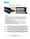
STM-1 O/E Converter User Manual Revision 1.0 2004/9 1. INTRODUCTION .......................................................................................................... 1 2. TYPICAL APPLICATION ........................................................................................... 1 3. PANEL ARRANGEMENT ........................................................................................... 1 4. 3.1. FRONT PANEL ARRANGEMENT ................................................................................. 1 3.2. REAR PANEL ARRANGEMENT ................................................................................... 3 3.3. LOOP BACKS ............................................................................................................ 3 INSTALLATION ........................................................................................................... 4 4.1. MECHANICAL........................................................................................................... 4 4.2. ELECTRICAL ............................................................................................................ 4 4.2.1. Power connection............................................................................................... 4 4.2.2. STM-1 electrical connections............................................................................. 4 4.2.3. STM-1 fiber connection...................................................................................... 5 5. OPERATION AND MAINTENANCE......................................................................... 5 6. SPECIFICATIONS ........................................................................................................ 5 6.1. CAPACITY ................................................................................................................ 5 6.2. STM-1 OPTICAL INTERFACE .................................................................................... 5 6.3. STM-1 ELECTRICAL INTERFACE............................................................................... 5 6.4. POWER ..................................................................................................................... 6 6.5. WORKING ENVIRONMENT ........................................................................................ 6 6.6. DIMENSION .............................................................................................................. 6 Note: Every effort is made to ensure that material printed in this manual is accurate until release. However we reserve the right to make improvements without prior notice. STM-1 O/E Converter Operation Manual 1. Introduction The STM-1 O/E Converter is designed to provide A and B two converters between electrical interface and optical interface of STM-1 signal. The converters features compactness, light weight, low power consumption and high reliability. The STM-1 O/E Converter operates on 1.31µm lasers, with a typical transmission distance of 40 km over single mode optical fibers. For longer hops, 1.55µm laser sources may be selected. Exterior power supply, all the functional blocks are integrated on a single PC board, which makes the modem compact and reliable. 220 V AC or -48 V DC power options are available by selecting an appropriate plug-in power unit. The two converters enclosure is a standard 19” wide 1U metal box, suitable for rack mounting, or as a desk top unit. 2. Typical application The STM-1 O/E Converter provides two converters between electrical interface and optical interface of STM-1 (155.520Mbit/s) signal of SDH or ATM network. The typical application is given below. SDH or ATM Network STM-1 O/E Converter Electrical Interface Optical Interface STM-1 O/E Converter Optical Fiber Optical Interface SDH or ATM Network Electrical Interface Fig. 1 Typical application example 3. Panel arrangement 3.1. Front panel arrangement The front panel of STM-1 O/E Converter is as shown below, STM-1 O/E Converter Operation Manual -1- B A O +3.3V +5V LOS OOL LOS O POWER E +3.3V +5V LOS E OOL LOS O POWER MODE DIP SWITCH SIGNAL O OOL E OOL E MODE DIP SWITCH SIGNAL Fig. 2 Front panel There are green, red and yellow LEDs on the front panel of the STM-1 O/E Converter. The following table lists meaning of all the LEDs and possible causes. The A and B converters are same. Table 1 LED descriptions LED +3.3V +5V O-LOS O-OOL E-LOS E-OOL Color green green red yellow red yellow Meaning when lit Note 3.3V Power switch on and OK 5V Power switch on and OK Loss of optical signal Unlock alarm of synchronization in optical signal Loss of electrical signal Unlock alarm of synchronization in electrical signal The A and B converters are same There are 8 DIP-switches in the front panel. They are used to set working mode of converters. Each of A and B two converters have 4 DIP switches. The following tables lists 4 DIP switches description. The A and B converters are same. Table 2 Working mode 1 2 3 4 5 NOTE. 4 DIP switches description 4 DIP states DIP-1 DIP-2 off on on on on on off on on on Description DIP-3 DIP-4 on on off on on on on on off on R x~Tx remote loop in optical Rx~Tx local loop in optical R x~Tx remote loop in electrical Rx~Tx local loop in electrical Normal O/E converter 1. The “on” is down, “off” is up for each DIP. 2. The A and B converters are same. Table 3 Working modes Loop test state Working modes description Optical STM-1 mode1 mode2 Electrical STM-1 mode3 mode4 mode5 Normal O/E converter NOTE. The A and B converters are same. -2- STM-1 O/E Converter Operation Manual 3.2. Rear panel arrangement There are STM-1 optical interfaces, STM-1 electrical interfaces, power switch and power in port in Rear panel. There are two types of The STM-1 O/E Converter, ~220V AC and – 48V DC, according to the power supply. Both of their rear panels show in following figures. The rear panel of STM-1 O/E Converter is shown below, IN FIBER IN OUT OUT IN FIBER IN OUT OUT ON 1 OFF 0 OPTICAL SOCKETS BNC SOCKETS (a) IN -48V POWER IN -48V SWITCH -48V DC power supply panel FIBER IN OUT OUT OPTICAL SOCKETS (75Ω) IN FIBER IN OUT OUT ON 1 OFF 0 B A BNC SOCKETS (75Ω) OPTICAL SOCKETS BNC SOCKETS (75Ω) (b) OPTICAL SOCKETS ~220V SWITCH 220V AC /50Hz BNC SOCKETS (75Ω) -48V B A ~220V POWER IN ~220V AC power supply panel Fig. 3 Rear panel For A or B STM-1 O/E Converter, the STM-1 electrical interfaces are BNC sockets, “IN” is incoming STM-1 electrical signal and “OUT” is outgoing STM-1 electrical signal. And the STM-1 optical interfaces are SC type or FC type sockets, pay attention to the input and output relationship. Do not bend fiber to sharp angles to prevent damage. Do not look directly into the fiber end or the Tx connector socket for extended time; it may be harmful to the eyes. 3.3. Loop backs The STM-1 O/E Converters support panel DIPs switch control of loop backs to allow for installation and maintenance checks. STM-1 O/E Converter Operation Manual -3- 4. Installation 4.1. Mechanical The dimension of the STM-1 O/E Converters is shown below. 440 mm 125 mm 44 mm 31.8 mm A O B E +3.3V +5V LOS OOL LOS OOL O E O E +3.3V +5V LOS OOL LOS OOL O E 465mm Fig. 4 Mechanical dimension 4.2. Electrical 4.2.1. Power connection Plug-in power unit is installed inside the power chamber. Two types of power units are available, 220V ac, or –48V dc. When AC unit is installed, the power inlet, a fuse, and a switch are integrated with the unit , as shown in the diagram below. inlet E N L fuse Fig. 5 AC power module Use the power cord supplied with the STM-1 O/E Converters. Plug in the power cord to the ac power inlet at the back of the power chamber. Be sure to use a wall outlet with correct voltage and a secure earth connection. When –48V DC power is selected, a cover plate is fixed on the chamber by screws. –48V DC power connector is on the right side of the power chamber. Connect to –48V power source using a pair of wires about 1mm in diameter to the power-in connector. Remove about 10mm of the protective insulator from the wire end. Prepare the wire end with solder. Push inward the yellow release lever on top of the connector with a screw driver, plug the prepared wire end well into the hole, then release the push. 4.2.2. STM-1 electrical connections There are BNC sockets for 75Ωcoaxial STM-1 electrical interface for A or B converter. -4- STM-1 O/E Converter Operation Manual 4.2.3. STM-1 fiber connection Use SC or FC type connectors to connect the STM-1 O/E Converters to the transmission cable. Pay attention to the input and output relationship. Do not bend fiber to sharp angles to prevent damage. Do not look directly into the fiber end or the Tx connector socket for extended time, it may be harmful to the eyes. 5. Operation and maintenance When all the connections are down, switch on the Converters. Observe all the alarm LED’s for any possible installation errors. Check the output optical power using an optical power meter. The reading should be within specification. Measure the optical power at the receiver end. Make sure that the power level is between the maximum allowable input power and sensitivity given in the specification. It is preferred to leave a margin of few dB’s for stable operation. 6. Specifications 6.1. Capacity A and B two STM-1 O/E converters. 6.2. STM-1 Optical interface ITU-T G.957 STM-1. Line rate: 155520 kbps Line code: Scrambled NRZ Wavelength: 1.31μm(typical) 1.55μm(optional) Connector: SC or FC Optical: S1.1 (typical), L1.1(optional) 6.3. STM-1 electrical interface ITU-T G.703 Bit rate: Line code: Impedance: 155520 kbps±20ppm CMI 75Ω (unbalanced) STM-1 O/E Converter Operation Manual -5- 6.4. Power DC type: AC type: Power consumption: -48V(-36V to -60V) ~220V(165V~265V) ≤3W 6.5. Working environment Temperature: Humidity: 0 ~50°C ≤90% non condensing 6.6. Dimension Width: Height: Deep: -6- 440mm 44mm 125mm STM-1 O/E Converter Operation Manual


![Manual[DOWNLOAD]](http://vs1.manualzilla.com/store/data/005715994_1-2fafd5cf8faf458a6c3437b6894f1203-150x150.png)