1
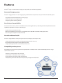
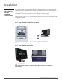
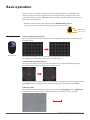
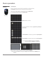
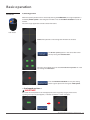
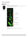
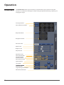
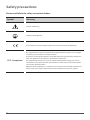
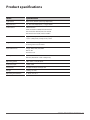
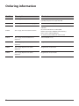
NEW PARADIGM FOR CELL BASED ASSAY
User Manual
Copyright
NanoEnTek Inc. All rights reserved.
Table of contents
Product components
4
Cleaning and Maintenance
51
Product overview
5
Troubleshooting
52
Features
6
Warranty
53
Description
7
Safety precautions
54
- Front view
7
Product specifications
57
- Side view
7
Ordering information
58
- Rear view
8
Technical support
59
- Control box
9
Installation
10
- Unpack the instrument
10
- Remove the filter change
10
lock module
- Install the instrument
11
- Place the instrument
13
- Operating environment
14
- Cautions
14
User interface
15
- GUI
Basic operation
15
17
- Moving
17
- Selection
18
- Zoom
20
- Focus
21
- Size bar
21
Operation
22
- Preview menu
22
- Option menu
28
- Data menu
36
- Setting menu
42
Quick operation guide
45
- Image capture, save and overlay
45
- Multi well default position and auto focus
47
- Manual position set and manual focus
49
JuLI™Stage, New paradigm for cell based assay
3
Product components
The JuLI™ Stage, Automated cell imaging system is shipped with the following components.
Please check all components listed below when the instrument is delivered.
PC will be shipped separately because it is optional.
If any item is missed or damaged, contact your local distributor or e-mail [email protected].
JuLI Stage main instrument
TM
Control Box
USB Cables (20 ~ 43 cm)
1 EA
2 EA
Connection Cable
Objective lens (4x, 10x, 20x)
1 EA
3 EA
1 EA
Power cord with 4 adaptor cords
(4 pcs/set, for U.S./Canada/Taiwan/Japan,
Europe or UK)
1 SET
10x lens is factory-installed with the
JuLI™ Stage main instrument.
User manual
Quick manual
1 EA
1 EA
Quick manual
NanoEnTek Inc. (HQ) 5, Digital-ro 26-gil, Guro-gu, Seoul, 152-740, Korea / Tel: +82-2-6220-7940, Fax: +82-2-6220-7721
NanoEnTek USA Inc. 5627 Stoneridge Drive Suite 304, Pleasanton, CA 94588, USA / Tel: +1-925-0108, Fax: +1-925-225-0109
www.nanoentek.com / [email protected]
NESMQ-JST-001E(V.0.0)
Copyright
4
NanoEnTek Inc. All rights reserved.
Product overview
A fully-automated, fluorescence live cell imaging system that acquires cell images directly from various cell culture
plates (6 to 384 well) and dishes in an incubator. JuLI™ Stage supports multi-channel fluorescent colors, multiple objective lenses, and sensitive filter-based optics to optimize for various live cell assays. In addition, it enables users to support quantified cellconfluence results with low variation and the growth curve using image-based analysis with bright
field.
Compact, compatible and automated fluorescence cell imaging system of live cell imaging from
inside your cell culture incubator!
Suitable for the following applications:
• Live cell imaging (time lapse)
• Cell culture quality control
• HCS cell imaging analysis (6 to 384 well)
• Cell-based assay optimization
• Image stitching
• Angiogenesis
• Scratch-wound assay
• Neurite growth
• Angiogenesis
• Protein expression
• Kinetic imaging and cell differentiation
• Cell growth monitoring
• Cell culture optimization
• Stem cell development
• Cell proliferation
• Cell cytotoxicity
• Cell migration study
• Cell differentiation
JuLI™Stage, New paradigm for cell based assay
5
Features
The JuLI Stage an automated cell imaging analyzer, offers you the following benefits,
TM
Automated imaging system
The JuLI™ Stage provides a live cell imaging using automatic focus and precise one by one multi-well control system.
- Fully automated and motorized X-Y scanning stage
- Auto focusing on every single position
- Image tiling with a stitching function
Sensitivity and expandability
The sensitive CCD camera, multi-channel fluorescence and magnification (4, 10 & 20 X) provide the powerful detection
capabilities required for various cell-based assays.
- High-sensitivity monochrome CCD
- Multi-channel fluorescence imaging (3 color fluorescence (GFP, RFP and DAPI) and bright channel)
- User-changeable objective lens (4, 10 & 20 X)
Versatile and Powerful S/W
The JuLI™ Stage software allows you to generate live cell imaging and analysis easily.
- Image capturing and time-lapse recording with multi-position scanning
- Navigation function to figure out the optimal position
- Image stitching function to scan the whole well at once
Compatibility and easy to use
The compact and ready to use system can be operated in an incubator and it can be controlled by the JuLI™ Stage
software from outside.
- Compact and compatible to CO2 incubator
- 23” full HD All-in-one touch screen PC control
- Simple steps for the system setup and operations
- Compatibility with various brands of well plates by auto adjustment function
6
Plate holder
Automatic stage
Description
Front view
Main body
Cover
(UV LED,
Blueyou use the JuLl™ Stage
Used to protect test samples from external light.
When
LED, Green LED)
in an incubator, the cover can block out light from the outside.
Main body
Front view of the JuLl™Stage.The main body is composed of LED, Filters
(Fluorescence mode) and optic parts.
Cover
Main body
(Rear
view)
(LED,
Filters
(Fluorescence mode) & optic parts)
[Front view]
Side view
LED (Bright mode)
LED is used for bright image viewer.
Vessel holder
This is a holder for sampling plates. The capacity is 6 well to 384 well.
Automatic X-Y
stage
The automatic X-Y stage makes it possible for you to move to the position
you want.
Lens holder
This is a holder for changeable lens.
Main device
LED
LED (Bright
(Bright)mode)
Vessel
holder
Plate holder
Automatic X-Y
stage
Automatic
stage
Main body
(UV LED,
Blue
Lens
holder
LED, Green LED)
[Side view]
JuLI™Stage, New paradigm for cell based assay
Cover
7
Description
Rear view
Fan
Machinery cooling system.
Connection port
Connect the JuLI™ Stage main instrument with the control box.
Power inlet
Connect the instrument to an electrical outlet using the supplied power
cord and the appropriate plug, based on the electrical outlet configuration
in your country.
Fan
Connection port
Power inlet
[Rear view]
8
Description
Control box
Serial and camera
LED
Connection port
When the PC and the control box are properly connected, the red light is
turns on.
Connect the JuLI™ Stage main instrument with the control box
Serial port
Control the camera in the JuLI™ Stage main instrument.
Camera port
Control the JuLI™ Stage main instrument operating.
Serial connection LED
Camera connection LED
Connection port
Serial port
Camera port
JuLI™Stage, New paradigm for cell based assay
9
Installation
Unpack the
instrument
1. Open the box and remove the material foam in the box.
2. Carefully lift the instrument out of the box, holding it by handholds in the bottom of the base.
3. Place the instrument on a flat, level surface (table or incubator).
IMPORTANT!
Do not lift the JuLI™ Stage by condense arm.
Remove the
filter change
lock module
1. Unscrew the filter change lock module screw until they spin freely.
2. Gently pull filter change lock module screw out, away from the instrument.
Filter
Filterchange
changelock
lock module
module
IMPORTANT!
Remove out the Filter change lock module by turning it counterclockwise to prevent the damage
of the instrument before plugging the power cord into power outlet and turning on the JuLI™
Stage.
10
Installation
Install
the instrument
1. Connect the PC and the Control box (Serial port, Camera port) using two USB cables.
(PC Monitor Resolution: 1920 ×1080 pixels)
☞ Note: Check the connection on the rear side of the PC.
1-1. Plug the power cord into the rear side of the PC.
Power port
USB port
2. Connect the JuLI™ Stage instrument and the Control box and using the connection cable.
☞ Note: Make sure for connection port direction of control box before connecting.
2-1. Plug the power cord into the rear of instrument.
3. Plug the power cord of PC and instrument into the electrical outlet.
☞ Note: Be sure to use only the power cord supplied with your instrument.
Powering the instrument with an unapproved power cord may damage the instrument.
JuLI™Stage, New paradigm for cell based assay
11
Installation
Install
the instrument
4. Turn the PC and the Control box on by pressing the Power button.
5. Double-click the JuLI™ Stage icon on Desktop. The JuLI™ Stage software starts up.
☞ Note: The JuLI™ Stage will be ready to use after initialization is completed when power on.
12
Installation
Place
the instrument
into the
incubator
(or to the table)
Live-cell images from various cell culture dishes are directly captured in a cell culture incubator.
This design allows an instrument to be installed in an incubator, and prevents the contamination
by maintaining a sterile environment. The intuitive graphic user interface also provides quick and
convenient use in a cell culture incubator while capturing time-lapse imaging.
The JuLI™ Stage operates in standard size of incubator. The JuLI™ Stage can be used in both inside
and outside incubator.
JuLI™ Stage installed inside of the incubator
JuLI™ Stage installed on the table
IMPORTANT!
Lay a cover if the instrument is installed on the table to protect test samples from
external light.
JuLI™Stage, New paradigm for cell based assay
13
Installation
Operating
environment
• Allow at least 10 cm (4 inches) free space at the back of the instrument to allow for proper ventilation and prevent overheating of electronic components.
• Set up the JuLI™ Stage away from direct light sources, such as windows. Ambient room lighting
can enter the imaging path and affect the image quality.
• Place the JuLI™ Stage on a level surface away from vibrations from other pieces of equipment.
• Operating temperature range: 5° - 40°C (41° - 104°F)
• Relative humidity range: 20 - 95 %.
Cautions
IMPORTANT!
The JuLI™ Stage is optimized into standard size of cell culture incubator.
It is recommend that the temperature should be stabilized in case of a small size incubator before
using the instrument.
Warm up the JuLI™ Stage for 2 hours before monitoring.
The power should be on when warming up the instrument.
The well plate’s cover should be wetted by the cell culture media before monitoring.
This step is required to avoid condensation inside the well plate cover for monitoring.
Avoid exposing the JuLI™ Stage to UV light.
UV light may degrade components, including plastics. Damage from UV exposure is not covered
under the manufacturer’s warranty.
Always wipe the surfaces with ethanol-soaked paper towels.
Do not directly spray ethanol anywhere on the JuLI™ Stage.
14
User interface
GUI
The JuLI™ Stage software allows you to generate live cell imaging and analysis easily.
- Image capturing and time-lapse recording with multi-position scanning
- Navigation function to figure out the optimal position
- Image stitching function to scan the whole well at once
The JuLI™ Stage is a fully automated imaging system controlled by the integratedthe JuLI™ Stage
software. The software, accessed the mouse, controls the automated X-Y axis stage and features
imaging and analysis tools.
Preview menu
Optionview menu
JuLI™Stage, New paradigm for cell based assay
15
User interface
GUI
Data menu
Setting menu
16
Basic operation
The JuLI™ Stage can be used in combination with PC (Monitor Resolution 1920x1080) which
enables users to operate the instrument using the computer mouse and keyboard. The JuLI™
Stage basic operations use the mouse for moving, selecting and zooming in/out. The detailed
explanations are listed below.
☞ Note: This manual describes the mouse function in Default setting (Type 1).
If necessary, you can change the mouse setting type the Setting menu.
Right: Moving
Left : Selection
Moving
Right mouse
1) Inter well: Moving among wells
Move the stage to the well you want by clicking the Right button of the mouse in both preview
and option menu.
The stage is moved from A-1 to A-2 by clicking the right button of the mouse.
The selected well is marked by a yellow circle as shown above.
2) Intra well: Moving within the well
The stage is moved to a position you have selected on the navigation window by clicking the
right button of the mouse in both preview and option mode.
The stage focuses in the center of the well when the well is selected. The selected image is marked
by red square when the specific spot is selected by clicking the right button of the mouse.
3) Moving in view
The stage is moved to the spot you assigned in the view field by Dragging with the right button
in both preview and option mode. The moving distance is marked by a red line as below.
172.31µm
JuLI™Stage, New paradigm for cell based assay
17
Basic operation
Selection
1) Selecting well
The well is marked by a grey color when the specific well is selected by clicking
The Left button. Click once to select and click once more to deselect.
☞Note: The JuLI™ Stage supports selecting function only in the Option menu.
The selecting function does not work in the Preview menu.
Left mouse
None of 24wells is selected
The selected well A-1 is marked by a grey color by pressing the
specific well.
The first well line is marked by a grey color when pressing line 1.
The “A” well line is marked by a grey color when pressing line A.
☞ Note: Deselection: Select each well again or drag the
selected wells with the Shift key on the keyboard.
Select any well or any well lines with the left mouse button by dragging.
☞ Note: Deselection: Select each well again or drag the selected wells with the Shift key on the
keyboard.
18
Basic operation
Selection
2) Selecting position
When the specific position well is selected by clicking the Left button, the assigned position is
marked by Green square in the Navigation window. Press the Position set button in order to
confirm.
The JuLI™ Stage supports the multi-selection functions.
Left mouse
None of the positions in the Navigation window are selected.
The Green square appears in the center of the well
when pressing the Default button.
The JuLI™ Stage allows users to select more than one position in a well
by clicking the Left button.
Press the Position set button to save your setting
that the green square will change to a Red square.
< Overlapped positions >
IMPORTANT!
If the two selected positions are overlapped, The JuLI™ Stage only assigns previous one.
i.g. Two green squares (overlapped) -> Position Set button -> One red square.
JuLI™Stage, New paradigm for cell based assay
19
Basic operation
Zoom
1) Zoom-in
Scroll up in the view field to use the zoom in the image.
The JuLI™ Stage supports zoom-in function in both the real view and captured images that allows
users to magnify specific position by scrolling up.
Mouse wheel
(Up and down)
< 1st zoom in >
Magnified navigation
< 2nd zoom in >
Magnified navigation
< 3rd zoom in >
Magnified navigation
2) Zoom-out
After zooming in, Scroll down to zoom out the view field in both real view and
captured images
20
Basic operation
Focus
3) Focus adjustment
Scroll up or down with Shift key on the keyboard for fine focus adjustment.
It is a same function with the Fine focus interface in the menu
Coarse focus interface
Mouse wheel
(Up and down)
Fine focus interface
☞ Note: Coarse focus function is in the menu. It is not supported by using the mouse wheel.
Size bar
4) Size bar
The JuLI™ Stage enables users to check Sample size and moving distance by
wheel dragging.
☞ Note: The size bar function is supported in the both Preview and Option menu.
JuLI™Stage, New paradigm for cell based assay
21
Operation
Preview menu
The Preview menu allows you to select basic system functions and is the first screen after
start-up. It is available for checking the sample, setting the optimized focusing, capturing and
merging the images.
Vessel type button
Focus information button
Map mode button
Navigation window
LED channel bar
Exposure bar
Brightness bar
LED power bar
Quick focus slide
Coarse focus button
Fine focus button
Auto focus button
Manual focus button
Capture button
Save button
Overlay button
Stage moving control button
Minimum & Exit button
22
Operation
Preview menu
Vessel type
Vessel
calibration
Focus
information
1. Press the Vessel button.
2. Select the Vessel type, which is used for selecting the sample vessel category.
3. Press the Vessel button again to close the window without calibration.
1. Press the Calibration button, if necessary.
2. Set the calibration options from up to bottom.
Step 1) Move to A1 and check the A1. Set the calibration options
by checking the up and down/ bilateral symmetry.
Step 2) Move to A2 and check the A2. Set the calibration options
by checking the up and down/ bilateral symmetry.
3. Press the Close button to exit.
1. Press the Focus information button.
2. The focus information button is designed to provide the focus setting information
about each well.
e.g. A1: Complete Bright focus
A2: Complete Bright and GFP focus
A3: Complete Bright, GFP and RFP focus
JuLI™Stage, New paradigm for cell based assay
23
Operation
Preview menu
1. Press the Map mode button.
2. Press the Map option button which will appear after pressing the Map mode button.
3. Select the LED channel and image size, and check whether or not to use auto focus function.
4. Press the Make a Map button.
5. Press the Cancel button to return to previous screen without setting.
6. Load map button will be activated after finishing the map making.
7. Refer to Quick guideline for more details (page 45).
Navigation
window
1. Preview well is marked by a Yellow circle.
2. The field you selected is marked by the Red square in the Navigation step.
Map mode
☞ Note: The size of red square, which is field of view, depends on vessel type.
24 well plate
96 well plate
LED channel
24
1. Select one of the LED channels which will be applied in the preview.
2. Click other buttons to change LED channel, if necessary.
3. Click the button you selected once more to turn off.
Operation
Preview menu
Camera set
Camera setting allows users to customize the user interface within the range of
setting values. To adjust the illumination intensity, use the Exposure and Brightness
bar. To adjust the power of light sources, use the LED power bar.
Exposure range : 5 ms ~ 500 ms
Brightness range : 0 ~ 40
LED power range : 1 ~ 10
Focus
Focus menu is used for finding the position of sample easily and supports
both Auto and Manual Focus.
1. Quick focus slide: Click to use quick investigation function.
2. Adjust the focus using the Coarse and Fine focus button.
[Coarse
[Coarsefocus
focusbutton]
interface]
Larger step which moves up or
down rapidly.
[Fine
[Fine focus
focusbutton]
interface]
Smaller step which moves short
distances minutely.
☞ Note: Scroll up or down with Shift key on the keyboard for fine focus adjustment.
Auto focus
Press the Auto Focus button after checking the contours of cells which appeared.
Manual Focus
1. Adjust the best focus by pressing the Fine Focus button.
2. Press the Manual Focus button.
3. Press the OK button when the pop-up window appears.
4. Check the information about manual focus setting by the Focus button.
[Coars
Larger
down
[Fine f
Smalle
distan
[Coars
Larger
down
[Fine f
Smalle
distanc
☞ Note: The optimal focusing position is suggested by the JuLI™ Stage Auto Software.
Manual focus is also available if the suggested focusing position is not optimal.
JuLI™Stage, New paradigm for cell based assay
25
Operation
Preview menu
Press the Capture button to capture the image.
Save image
Press the Save button to save the captured image.
Enter the file name and store the path when the pop-up window appears.
Confluence
Press the Confluence button to check the confluence value in the bright
field. The JuLI™ Stage supports two kinds of parameters
(Sensitivity and Background level) which users are able to choose from A ~ C type.
Capture image
26
Operation
Preview menu
1. Capture images from more than two channels. (Bright, GFP, RFP or DAPI).
2. Press the Overlay button, then the editing window will appear.
3. Press the Save button in the overlay window to save the overlapped image.
Stage moving
control
Press the Stage moving control button to control the X-Y stage position.
Overlay image
☞ Note: The stage is also moved to the spot you assigned in the view field by Dragging
with right button of the mouse.
Minimum &
Exit button
Minimize window or close the operation program using the Minimize and the Close button.
JuLI™Stage, New paradigm for cell based assay
27
Operation
Option menu
Camera setting
option
The Option menu allows you to set the sample monitoring options. It is composed of two
parts (Camera setting and Monitoring setting option).
Camera set part contains detailed functions such as assigning well/specific position, camera
setting and focus settings (auto focus, point to focus and manual focus).
☞ Note: The functions and buttons commonly used in Preview menu, Please refer to the
details in Preview menu section.
Vessel type button
Focus information button
Map mode button
Navigation window
Position set button
Default button
Undo button
Clear button
Camera option tap button
LED channel bar
Exposure bar
Brightness bar
LED power bar
Quick focus slide
Coarse focus button
Fine focus button
Auto focus button
Manual focus button
Stage moving control button
Manual focus toggle button
Auto Focus toggle button
Point to Focus toggle button
Minimum & Exit button
28
Operation
Option menu
Navigation
position set
Position set :
Once Position set button is pressed after assigning an area you
want, the area will be changed into Red square at navigation window.
Default button : Select well and then press Default button, center value of
well will be assigned. If you want to assign the area, press the Position Set
button.
Undo button :
When you want to Cancel the specified location with the Right Mouse button,
specified locations are cancelled chronologically from the most recent specified
location.
Clear button : Delete all of the set values in the well (navigation window).
Camera
option tap
Press the Camera Tap button to select the option.
Manual Focus
Manual Focus Toggle button is used during the monitoring.
In this case, Auto focus toggle button is set “off” automatically.
Auto Focus
Auto Focus Toggle button is used during the monitoring.
In this case, Manual focus toggle button is set “off” automatically.
Point to Focus
This button activates Auto Focus in all area, in case of several areas shooting in
one well. This button is only activated when auto focus toggle button is set “On”.
JuLI™Stage, New paradigm for cell based assay
29
Operation
Option menu
Focus offset
Focus offset is used to revise the focus if the auto-focus function does not provide optimal focus
results corresponding to your sample. This is more convenient to operate in comparison with
manual focus function.
Focus offset button can be used when auto focus mode is turned on.
This allows a user to set specific range of revision when there are differences among
channels.
Steps are as below.
1. Adjust the focus according to your sample, and then press the Focus Offset button
(When the autofocus mode is turned on).
2. The JuLI™ Stage Software automatically adjusts the Optimal focus corresponding to your
sample in the bright field.
3. If necessary, edit the focus using the Fine focus button and then press the Set button to
confirm. (The JuLI™ Stage automatically has memory for z-value; distance between
auto-focused and a user moved position).
4. Select the channel using the LED channel bar.
5. Edit the focus following step 3 and then press the Set button. The z-value will be displayed.
6. If necessary, follow step 4 ~ 5 in different LED channel.
☞ Note: Focus offset may not provide optimal focus when sample is damaged.
30
Operation
Option menu
Monitoring
setting option
Monitoring set part provides various setting functions to assigning tile, setting
detailed monitoring condition (interval and cycle) and setting image format.
☞ Note: The functions and buttons commonly used in Preview menu, Please refer to the
details in Preview menu section.
Vessel type button
Focus information button
Map mode button
Navigation window
Position set button
Default button
Undo button
Clear button
Monitoring option tap button
Title name bar
LED channel bar
Stitching toggle button
Stitching range bar
Growth curve toggle button
Wound healing toggle button
Image format bar
Total time bar
Interval time bar
Cycle number bar
Start button
Cancel button
Minimum & Exit button
JuLI™Stage, New paradigm for cell based assay
31
Operation
Option menu
Move among options using the Setting Tap.
Monitoring
option tap
IMPORTANT!
Warm up the JuLI™ Stage for 2 hours before monitoring.
The power should be on when warming up the instrument.
The well plate’s cover should be wetted by the cell culture media before monitoring.
This step is required to avoid condensation inside the well plate cover for monitoring.
The 15 minutes of time interval is recommended to prevent from cell damage.
The cell may be damaged by LED less than 15 minutes interval in the case of monitoring in Bright
& GFP mode. However, the optimal time interval depends on cell lines.
Title name
To start monitoring, assign the title using the pop-up keyboard.
LED channel
Select the channel using the LED channel bar.
Stitching option
Press the Stitching toggle button to apply stitching while monitoring.
Set the Range of stitching (2 X 2 ~ 10 X 10, 4 ~ 100 images.)
Growth curve
option
Press the Growth curve toggle button to make growth curve while monitoring.
The growth curve can be recalculated when editing data. To make the growth curve,
32
set the confluence parameters in the camera set part (Refer to page 28).
Operation
Option menu
Wound healing
option
Press the Wound healing toggle button to make wound healing curve.
The wound healing curve can be recalculated when editing data.
To make the growth curve, set the confluence parameters in the camera
set part (Refer to page 28).
Confluence
parameter
Once Confluence parameter button is selected, the setting window will be
shown up. After parameter is modified, press the Apply button to see image
Image format
Image format can be saved as 4 types of file. One type of file can be selected at a time.
Time set & Mode
Total time: Is not modified at this window and is displaced by calculating of
interval time and cycle.
Interval time: When a well is selected, estimated time shows up with red color depending on
selected condition. With reference select interval time. The interval time can not be set shorter
than the red estimated time.
Cycle: Select number of image in each position.
☞ Note: You can edit the monitoring cycle while monitoring by pressing Pause button.
The new cycle value that you will enter is longer than the current cycle.
When Each bar is double-clicked, the interval and cycle setting key pad shows up.
IMPORTANT!
The 15 minutes of time interval is recommended to prevent from cell damage.
The cell may be damaged by LED less than 15 minutes interval in the case of monitoring in
Bright & GFP mode. However, the optimal time interval depends on cell lines.
JuLI™Stage, New paradigm for cell based assay
33
Operation
Option menu
Press the Start button to move to the next step.
Start button
Cancel button
Ready to start
Press the Cancel button to reset.
Ready to start window shows all setting information you assigned.
Press the Play button to start program after checking the settings.
Title name
Selected wells
Selected channels
Navigation window
Total time
Interval time
Cycle numbers
Monitoring mode
display button
Graph display button
Stop button
Start button
☞ Note: You can edit the monitoring cycle while monitoring by pressing Pause button.
The new cycle value that you will enter is longer than the current cycle.
34
Operation
Option menu
The Graph button shows all graphs so far while the instrument is working.
Confluence table
The Confluence Table button provides back data sheet of Graph.
Graph data
JuLI™Stage, New paradigm for cell based assay
35
Operation
Data menu
Data menu provides the function to view and edit the captured images. In the data menu users
are able to check, edit data (cell growth curve, wound healing) and make a movie.
Once you selected the title, the JuLI™ Stage shows test conditions including vessel type, well
captured position, LED channel condition, interval time and cycle number.
Title list
List bar
Vessel display
LED set display
Navigation display
Total time bar
Interval time bar
Cycle number bar
Mode display
Graph display button
Stitching button
Export button
Edit button
Minimum & Exit button
36
Operation
Data menu
The selected title is marked by green color when clicking a title.
Vessel display
The color of vessel contains information about test conditions.
Title list
Grey circles: Captured well
Red circles: Captured well and selected for review
LED set &
Navigation
display
LED set & Navigation display contain the condition of LED channel and position of captured
images. The JuLI™ Stage can hide or open information by pressing the LED channel buttons.
The captured position is marked by Red square as below. Click the red square to check the images in detail.
JuLI™Stage, New paradigm for cell based assay 37
Operation
Data menu
Time setting condition and the mode information are displayed
Display data
Press the Display Data button (Graph and Confluence table) to check growth curve and confluence data.
Time set & Mode
Display data contains the Graph and Confluence table button that open related information. For
example, press the graph button to check the wound healing and growth curve.
☞ Note: If the growth curve or the wound healing mode is not selected in option menu, the button
may not be activated. If necessary to obtain growth curve data, you can edit confluence data
table in Edit mode.
Display export
Press the Export button to export the captured images. The multiselection function is supported.
☞ Note: Can access or download the image data through JuLI™ Stage / TIMELAPS folder in PC also.
Display edit
38
Press the Edit button to get additional analysis and data with test results.
(described in next page for more details)
Operation
Data menu
Edit operation allows users to get additional analysis and data with test results.
This Editing operation mode gives you excellent imaging function to overlay image & movie
and reset confluence parameter for more accurate growth curve.
Overlay option
Edit the parameters in overlay tab of Edit menu according to your test condition. Press the Save
button and assign title and storing path.
Data edit
JuLI™Stage, New paradigm for cell based assay 39
Operation
Data menu
Overlay movie
save as
40
Edit the parameters in overlay tab of Edit menu and move to the Movie tap.
1. Title: Click the Title bar and type the title and storing path.
2. Frame rate: Choose one of the frame rates. (1, 5, 10, 15 or 20 fps)
3. Running time: Expected running time depends on numbers of
images in folder and frame rate.
4. Make movie : Press the Start button to make a movie
5. AVI file will be created in storing path you assigned.
Operation
Data menu
Growth curve
save as
1. Select tile of existing data to make growth curve and click the Edit button.
2. Edit the parameters in the Graph tap to set the optimal condition for confluence.
3. Wound healing mode: Turn on the wound healing toggle button, if necessary.
4. Press the Make a graph button to check vessel images
5. Select the Well and LED channel and Press the Apply button.
JuLI™Stage, New paradigm for cell based assay
41
Operation
Setting menu
Setting menu contains information about the JuLI™ Stage as well as several user preference and
other Settings. Setting menu allows users to edit settings about the software & firmware information and basic operations.
Version Auto check
Software information
Firmware information
Lens information
Data path information
Mouse control buttons
Serial number bar
Administration mode
42
Operation
Setting menu
The JuLI™ Stage checks for the latest version of software or firmware and automatically
display the information window whenever it starts up. This is available only for PC with
internet connection.
Software
information
Software information is used to update through the USB drive and network connection.
Firmware
information
Firmware information is used to update through the USB drive and network connection.
Version Auto
check
☞ Note: Press Update button if you have the update file for the software or firmware. Or press
Check button and then Update button if the PC has a internet connection for updating.
Lens information
Changing lens
Provides lens information when it moves and checks the size. The lens can be changed by hands
and the size of field of view (square) on navigation window is also changeable as lens information.
1. Move the X-Y stage to the center position using the Stage moving control button.
2. Loosen and rotate the current lens counterclockwise to remove it from the holder.
3. Place the new lens on the holder and rotate clockwise. Be sure to rotate the objective until it is
tight in the holder.
JuLI™Stage, New paradigm for cell based assay
43
Operation
Setting menu
Allows users to assign the save path and check disk volume
Mouse type
Mouse control is used for changing basic function of mouse.
Data path &
system info
☞ Note: Type 1 is factoring setting. Can change the type, if necessary.
Serial info
Shows serial number of the JuLI™ Stage main instrument.
Admin mode
Administration mode. It is for manufacturing engineers to set the system.
44
Quick operation guide
(Image capture , save and overlay)
1. Select the Preview menu.
2. Press the Vessel button.
3. Select the Vessel type according to your sample
when well type list appears.
4. Check the selected Vessel type and press Vessel button
again to finish setting.
5. Move to the well and position you want using the right
button of mouse. You can check the vessel image and
the moving state in the navigation window and view field.
6. Select the LED channel for capturing images.
7. Adjust Exposure, Brightness and LED Power,
if neccessary.
JuLI™Stage, New paradigm for cell based assay 45
8. Find optional focus and adjust with Focus bar & buttons
9. Press the Capture button to start capturing images.
10. Press the Save button to save the captured images,
if necessary.
11. Once pop-up window appears, assign the storing
path and file type, and press the Save button to confirm.
12. If necessary to capture additional images in
different channel, select other LED channel.
13. Follow Step 6 ~ 10 repeatedly and save images for
each channel.
14. After pressing the Overlay button, the overlapped
images, which captured in each channels, will be
displayed.
15. When Overlay button opens the Overlay setting
window, edit parameters according to your preference.
And then press the Save button to follow step
10 ~ 11(The images will be saved as).
46
Quick operation guide
(Multi well default position and Auto focus)
1. Select the Option menu and the camera tap will be
activated.
2. Activate the Vessel button by pressing.
3. Select the Vessel type according to your sample
when well type list appears.
4. Check the selected Vessel type and press Vessel button again to finish setting.
5. Select the LED channel.
6. Adjust Exposure, Brightness and LED Power,
if neccessary.
7. Select areas you want to capture by dragging with
left mouse button.
JuLI™Stage, New paradigm for cell based assay 47
8. The selected wells are changed to Grey color.
9. Press the Default button to equally capture
central position of all wells.
10. The assigned position is marked by Green square
on the navigation window.
11. Press the Position set button to complete setting
that the green square is changed to Red.
12. Press the OK button when pop-up window appears.
13. Once the wells are finally confirmed, they are
changed to Red color.
14. Turn on the Auto focus toggle button.
15. Select the Setting tap of monitoring option.
16. Refer to the detail options of Monitoring option tap
in the Option menu (page. 32)
48
Quick operation guide
(Manual position set and Manual focus)
1. Click a well you want to capture using right
mouse button.
2. Once the well is selected, the X-Y stage is automatically moved to center of well. Move to position you want
using right mouse button, and check where you
moved to within the navigation window.
3. Press the Manual focus toggle button.
4. Select LED channel.
5. Adjust Exposure, Brightness and LED Power,
if neccessary.
6. Find optional focus adjusting the Focus bar and
buttons.
7. Manual Focus button is used to assign optional
focus per each position. After setting the focus of
each position, press, the Manual Focus button to save
setting value.
JuLI™Stage, New paradigm for cell based assay 49
8. If necessary to set manual focus in other channel,
press the LED button and follow previous step 4 ~ 7.
9. After adjusting focus and assigning position,
press the Position Set button.
10. Press the OK button when the pop-up window
appears.
11. Once the wells are finally confirmed, they are
changed to Red color.
12. If necessary to set manual focus in other well,
follow the previous step 1 ~ 11.
13. Select the Setting tap of monitoring option.
14. Refer to the detail options of Monitoring option tap
in the Option menu (page. 32)
50
Cleaning and Maintenance
Clean the surface of the JuLI™ Stag with a damp cloth. To clean the LCD screen, turn off the JuLI™ Stage, disconnect the
power cable, and clean the LCD screen with a soft cloth lightly moistened with LCD cleansing detergent. Cleaning
the screen with excessive force can damage the LCD screen.
If liquid spills on the JuLI™ Stage, turn off the power immediately and wipe dry.
The JuLI™ Stage™ does not need regular maintenance. To troubleshoot problems
with the JuLI™ Stage™, contact Technical Support (Refer to page 58).
IMPORTANT! Never disassemble or service the JuLI™ Stage by yourself.
Unauthorized repairs may damage the JuLI™ Stage or alter its functionality, which will void your warranty.
Contact [email protected] or your local the JuLI™ Stage distributor to arrange for service.
IMPORTANT! The JuLI™ Stage is optimized into standard size of cell culture incubator.
It is recommend that the temperature should be stabilized in case of a small size incubator before using the instrument.
IMPORTANT! Warm up the JuLI™ Stage for 2 hours before monitoring.
The power should be on when warming up the instrument.
IMPORTANT! The well plate’s cover should be wetted by the cell culture media before monitoring.
This step is required to avoid condensation inside the well plate cover for monitoring.
IMPORTANT! Avoid exposing the JuLI™ Stage to UV light.
UV light may degrade components, including plastics. Damage from UV exposure is not covered under the manufacturer’s warranty.
IMPORTANT! Always wipe surfaces with ethanol-soaked paper towels.
Do not directly spray ethanol anywhere on the JuLI™ Stage.
JuLI™Stage, New paradigm for cell based assay
51
Troubleshooting
Intstallation
JuLI Stage does not
power up
Check on/off switch on back side of main device.
Check power source or contact your distributor.
LCD screen is black
Move the mouse.
Check if power supply is connected and power switch is on.
Reset the power button.
Monitoring
Poor image
(Too dark and too bright)
Re-optimize the brightness and exposure value.
Reset the power button
Dirty image
Swipe the stage with cotton swab carefully.
Eliminate any dust on the culture dish.
Check for and remove any condensation on thelid of the culture dish.
Time-lapse images become
dark or bright
Warm up the instrument for 2 hour before monitoring. (power should be
on when warming up the instrument)
Cell culture flask should be wetted by the culture media before making
a movie.
Eliminate any dust on the culture dish.
Remove any condensation on the lid of the culture dish.
To prevent any problem such as shaking of culture dish or inflowing light,
pay special attention when you open or close incubator door during
monitoring.
Problem for saving movie
file
Check available volume of the hard disk.
52
Warranty
NanoEnTek provides 1-year warranty service for defects of material and workmanship.
If any defects occur in the JuLI™ Stage, NanoEnTek provides free repair service for the defective parts at its discretion.
The following defects, however, are specifically excluded:
1. Defects caused by improper operation.
2. Repair or modification done by anyone other than NanoEnTek or an authorized agent.
3. Damage caused by substituting alternative parts.
4. Use of fittings or spare parts supplied by anyone other than NanoEnTek.
5. Damage caused by accident or misuse.
6. Damage caused by disaster.
7. Corrosion caused by improper solvent or sample.
For your protection, the JuLI™ Stage units being returned must be insured against possible damage or loss. NanoEnTek
cannot be responsible for damage incurred during shipment
of a defective instrument. It is recommend that you save the original packing material in which the instrument was
shipped. This warranty is limited to the replacement of defective products.
For any inquiry or request for repair service, contact [email protected] or your local distributor.
JuLI™Stage, New paradigm for cell based assay
53
Safety precautions
Review and follow the safety instructions below :
If water or other material enters the instrument, adaptor, or power inlet, disconnect the power cord and
contact a service person. For operating environment, refer to Product Specifications.
Do not touch the main plug or power cord with wet hands.
Always ensure that the power supply input voltage matches the voltage available at your location.
This instrument is air-cooled and its surfaces may become hot during operation.
During installing, leave a space of more than 10 cm (4 inches) around the instrument and do not place any
objects between the instrument and the walls.
Do not install the instrument on a slant or a place prone to vibrations, which induces he risk of instrument
malfunction or damage of the instrument.
Never insert any objects into the air vents of the instrument as this could result in electrical shock, personal
injury, and equipment damage.
Plug the power cord firmly into the wall outlet and AC adapter.
To avoid potential shock hazard, make sure that the power cord is properly grounded.
Be sure to position the equipment such that it is easy to disconnect.
Turn off the instrument before unplugging the power cord and/or moving the instrument.
If the instrument is dropped or broken, disconnect the power cord and contact a service person.
Disassembly of case will void warranty.
Use only authorized accessories (adaptor, power cord, and USB drive).
Warning
Class A equipment is intended for use in an industrial environment. In the documentation for the user, a statement shall be
included drawing attention to the fact that there may be potential difficulties in ensuring electromagnetic compatibility in
other environments, due to conducted as well as radiated disturbances.
54
Consignes de securite
Examinez et suivez les consignes de securite ci-dessous :
N’installez pas l’instrument dans un endroit humide comme une serre ou un incubateur pour eviter un risque de choc
electrique. Si de l’eau ou tout autre materiau penetre dans l’instrument, l’adaptateur, ou l’entrees d’alimentation, debranchez le cordon d’alimentation et contactez un technicien de service. Pour l’environnement d’exploitation, reportezvous aux specifications du produit.
Ne touchez pas la fiche ou le cordon d’alimentation principale avec les mains mouillees.
Assurez-vous toujours que la tension d’entree d’alimentation correspond a la tension disponible dans votre endroit.
Cet instrument est refroidi a l’air de sorte que ses surfaces peuvent devenir chaudes pendant le fonctionnement.
Lors de l’installation de l’instrument, laisser un espace de plus de 10 cm (4 pouces) autour de cet instrument et ne placez
aucun objet entre l’appareil et le mur.
N’installez pas l’instrument sur une pente ou un endroit soumis a des vibrations, ce qui induit le risque de dysfonctionnement ou d’endommagement de l’instrument.
N’inserez jamais aucun objet dans les orifices d’aeration de l’instrument, car cela pourrait entrainer un choc electrique,
des blessures chez les utilisateurs et des dommages d’equipement.
Branchez le cordon d’alimentation fermement dans la prise murale et l’adaptateur secteur aussi.
Pour eviter un risque potentiel de commotion electrique, assurez-vous que le cordon d’alimentation est correctement
mis a la terre.
Assurez-vous de positionner l’instrument de telle sorte qu’il soit facile de debrancher l’instrument.
Eteignez l’instrument avant de debrancher le cordon d’alimentation et / ou de deplacer l’instrument.
Si l’instrument est casse ou qu’il soit tombe, debranchez le cordon d’alimentation et contactez un technicien de service.
Ne demontez pas l’instrument et la garantie sera annulee en cas de demontage.
Utilisez uniquement les accessoires autorises (l’adaptateur, le cordon d’alimentation, et le lecteur USB).
Warning
Le produit de classe A est conçu pour l’utilisation dans un environnement industriel.
Dans la documentation de l’utilisateur, la déclaration doit être incluse pour attirer l’attention sur le fait qu’il peut y avoir des
difficultés potentielles pour assurer la compatibilité
électromagnétique dans d’autres environnements, en raison des perturbations rayonnées et conduites par l’électricité.
JuLI™Stage, New paradigm for cell based assay 55
Safety precautions
Review and follow the safety instructions below :
Symbol
Meaning
Caution and Warning
Protective earth (Ground)
This instrument and consumables conforms to the EC Declaration of Conformity.
FCC Compliance
56
This equipment has been tested and found to comply with the limits for a Class A digital
instrument, pursuant to Part 15 of the FCC Rules.
These limits are designed to provide reasonable protection against harmful interference
when the equipment is operated in a commercial environment.
This equipment generates, uses, and can radiate radio frequency energy and, if not installed and used in accordance with the instruction manual, may cause harmful interference to radio communications.
Operation of this equipment in a residential area is likely to cause harmful interference in
which case the user will be required to correct the interference at his own expense.
Product specifications
Items
Specification
Light source
Blue, Green, UV LED (Intensity adjustable)
Objective lens
4 X, 10 X & 20 X (Olympus) + Digital Zoom
Fluorescence
3 fluorescence
DAPI: Excitation 390/40, Emission 452/45
GFP: Excitation 466/40, Emission 525/50
RFP: Excitation 525/50, Emission 580LP
Camera
High-sensitivity monochrome CCD (Sony sensor 2/3”)
1,936 x 1,456 pixels (2.8 M), 53 FPS, 14 bit
Stage
Automated X-Y-Z Stage
Ex-changeable vessel holders
Exported formats
Image: JPEG, PNG, TIFF, BMP
Movie: AVI
Raw data: CSV
PC requirement
OS Widows Vista or more
Monitor (Resolution 1920 x 1080 pixels)
Operating power
100 – 240 V, 1.5 A, 50/60 Hz
Electronic input
12VDC, 5.0A
Dimensions
429 (W) X 310 (D) X 324 (H) mm
Weight
18.0 kg / 39.7 lbs
Operating environment
5 - 40 °C, 20 - 95 %
JuLI™Stage, New paradigm for cell based assay 57
Ordering information
Cat. No.
Description
Contents
JS1000S
JuLI™ Stage Starter pack
JuLI™ Stage basic set (JS1000), All-in-one touch screen PC
(JS0100),3 Objective lens (4X, 10X, 20X)
JS1000
JuLI™ Stage, Automated cell imaging system
Main device, Power supply, Control box
JP0100
JuLI™ Stage, All-in-one touch screen PC
CPU: Intel Core i5-4590S Processor (Qual Core, 6MB,
3.00GHz)
OS: Genuine Windows 8.1 64bit (ENG)
RAM: 8 GB (2x4 GB) 1600MHz DDR3L Memory
HDD: 1TB 2.5” SATA (5,400 Rpm)
23” Full HD (1920 X 1080) with touch screen
JP0150
JuLI™ Stage, External hard disk rive
(Optional)
Total 8 TB (4 TB x 2 ea)
JO0004
JuLI™ Stage, Objective lens (4 X)
(Optional)
Magnification: 4 X, NA: 0.16
JO0010
JuLI™ Stage, Objective lens (10 X)
(Optional)
Magnification: 10 X, NA: 0.3
JO0020
JuLI™ Stage, Objective lens (20 X)
(Optional)
Magnification: 20 X, NA: 0.45
58
Technical support
Visit our Website at www.nanoentek.com for :
· Technical resources, including manuals, FAQs, etc.
· Technical support contact information
· Additional product information and special offers.
For more information or technical assistance, please call or email.
NanoEnTek Inc. (HQ)
12F, 5, Digital-ro 26-gil, Guro-gu, Seoul, 152-740, Korea
Tel : +82-2-6220-7940
Fax : +82-2-6220-7721
NanoEnTek USA Inc.
5627 Stoneridge Drive Suite 304, Pleasanton, CA 94588, USA
Tel : +1-925-225-0108, +1-888-988-0108(Toll free)
Fax : +1-925-225-0109
Email
[email protected]
Website
www.nanoentek.com
JuLI™Stage, New paradigm for cell based assay 59
All the materials in this user guide are protected by Korean and international copyright laws. They
cannot be reproduced, translated, published or distributed without the permission of the copyright
owner.
JuLI™ Stage User Manual
Website : www.nanoentek.com
E-mail : [email protected]
Manufactured by : NanoEnTek Inc. (HQ)
12F, 5, Digital-ro 26-gil, Guro-gu, Seoul, 152-740, Korea
Tel : +82-2-6220-7940
Fax : +82-2-6220-7721
The information in this manual is described as accurately as possible. The changes involved in firmware
and software may be applied without notification.
Copyright ©2014 by NanoEnTek Inc. All rights reserved. Published in Korea.
Documentation: NESMU-JST-001E
Revision history: V.0.0 Date: OCT 2014
NESMU-JST-001E (V.0.0)
NanoEnTek Inc. (HQ)
5, Digital-ro 26-gil, Guro-gu, Seoul, 152-740, Korea
Tel : +82-2-6220-7940
Fax: +82-2-6220-7721
NanoEnTek USA Inc.
5627 Stoneridge Drive Suite 304, Pleasanton, CA 94588, USA
Tel : +1-925-225-0108, +1-888-988-0108(Toll free)
Fax: +1-925-225-0109
Email
[email protected]
Website
www.nanoentek.com