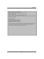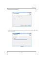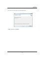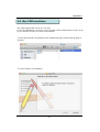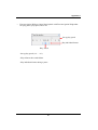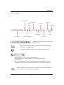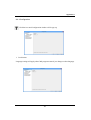
1
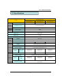
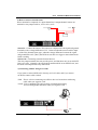
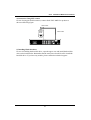
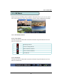
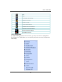
Digital Video Recorder
User’s Manual
New Prestige 04/08/16
1
Thank you for using our product.
1. This is user's manual for analog 960H 4ch, 8ch and 16ch DVR(Digital Video
Recorder).
2. This manual contains product specification and introduction, installation guide,
operating guide and other necessary matters for easy understanding. Users should
read this user's manual carefully for proper use.
3. Contents in this manual may be changed according to the specification change and
feature improvement without any notification.
4. This user's manual shall never be copied without prior agreement and violating this
may be a reason for legal punishment on piracy.
5. If there is any incorrect or insufficient content in this user's manual, notify it to
Customer Support Center.
2
CONTENTS
Contents
CH 1. Product Introduction`
1-1. Product Contents
1-2. Specifications
1-3. Product Characteristics
1-4. Name of Each Part
5
6
8
10
CH 2. Installation Guide and Cautions
2-1. Cautions
2-2. Product Installation
2-2-1. Power Connection
2-2-2. Connecting External Device
13
16
16
16
CH 3. How to Use
3-1. General Usage Information
20
3-2. Live Mode
3-2-1. Live mode control
3-2-2. Live mode feature
21
21
22
3-3. Search Mode
3-3-1. Search selection type
3-3-2. Play Mode
29
29
33
3-4. Setup Mode
3-4-1. Display
3-4-2. Record
3-4-3. Device
3-4-4. Network
3-4-5. System
34
34
38
43
58
65
3-5. Firmware Upgrade
71
3
CONTENTS
Contents
Trouble Shooting
73
Appendix A
Connecting using Web browser
74
Appendix B
Catcheye for Android mobile
112
Appendix C
Catcheye for iPhone
118
4
CH 1 Product Introduction
CH1. Product Introduction
1-1. Product Contents
After removing packing materials of this product, check whether all following
contents are included.
Main Body (DVR):
This converts the analog video and audio signal to
the digital signal and saves on HDD.
Adapter:
This 12V adapter supplies power to the product.
MOUSE:
This is an controller for convenience.
Program CD:
This contains the User’s manual and Client
Program for DVR.
Remote Controller:
This is an IR remote controller for convenience.
Battery:
These are 2(two) battery for the remote controller.
5
CH 1 Product Introduction
1-2. Specifications
New Prestige series
Model
Camera input
Video
Audio
New Prestige 04
New Prestige 08
New Prestige 16
4 BNC
8 BNC
16 BNC
Available source
Composite/960H/Mixed
Output
1 HDMI+1 VGA (simultaneously) / 1 Programmable SPOT with OSD
Audio input
4 RCA
Output
1 RCA
Sensor In
4 (NC / NO)
Alarm out
1 relay
Operating System
Embedded Linux OS
Display
Speed
Real Time
Resolution (Pixel)
1280X1024, 1280X720, 1920X1080
Split screen
Recording
1,4
1,4,6,8,9
CODEC
H.264 / JPEG for 3G, Dual CODEC
Resolution (Pixel)
960H(WD1), D1, CIF, Mixed
Picture quality
4 steps (Super, High, Medium, Low)
Speed
NTSC area
PAL area
Display
120fps@WD1
100fps@WD1
240fps@WCIF
200fps@WCIF
480fps@CIF
400fps@CIF
1,4
1,4,8,9
1,4,6,8,9,13,16
Search mode
Playback
Speed
NTSC
PAL
Fast/Slow speed
1,4,6,8,9,13,16
Calendar, Event ,POS , Panorama, Thumbnail
120fps@WD1
100fps@WD1
240fps@WCIF
200fps@WCIF
480fps@CIF
400fps@CIF
Normal, REW & FF [recorded speed x2, x4, x8, x16,x32,x64,x1/2,x1/4], Frame to
frame, Pause
6
CH 1 Product Introduction
1-2. Specifications
New Prestige series
Model
New Prestige 04
Network Interface
Speed
New Prestige 08
New Prestige 16
Gigabit Ethernet
15fps@WD1
15fps@WD1
15fps@WD1
Protocol
TCP/IP, HTTP, DHCP
Application
Windows 2000 / XP / Vista / 7 / 8 (PC Client system& IE)/MAC
Web Browser
Internet Explorer, Safari, Firefox
Smart phone App
CatchEye : Android, iPhone for live and search
Interface
USB 2.0 X 2
Backup
Backup device
External CD&DVD-RW, Network, Thumb Drive
1 SATA(No capacity limit ; 4TB of more)
The number of HDD
•Full GUI with alpha blending
•Individual setting of resolution, frame rates and picture quality
•Instant Replay
•Digital Zoom
•Mouse Control
•Weekly scheduler with holiday by 10 minutes setting
•Covert, Disable and Private function of cameras
•Motion Detection with 352 area setting
•Relay alarm output
•PTZ control by RS-485
Function •Daylight Saving Time and Network Time Setting
•Multi User Authority up to 8 Users
•Deinterlacer upon live and playback
•22 languages with full graphic
•Individual Network port setting
•Auto Deletion
•Import and Export the configuration
•Mirroring
•POS Interface
•Dual CODEC engine for independent video transmission
•Interactive setup via network
Power Consumption
24W
Operating Temperature
5 ~40℃(41~104F)
Others
Relative Humidity
Maximum 80% non-condensing
Dimension
300(W)×210(D)×48(H) mm
Network
7
CH 1 Product Introduction
1-3. Product Characteristics
1) High quality picture
This enables recording and playing high quality digital image based on H.264
compression method.
2) High reliability
With Embedded hardware and software design, this maintains higher product
reliability.
3) Simple usage
This allows users to use it conveniently by placing control buttons similar to existing
ones on VCR, and users can easily learn the usage.
4) Pentaplex System
Pentaplex System allows live, recording, backup, networking and playback
simultaneously.
5) Selectable recording setup
For recording methods, users can select the frame rate, resolution and video quality
individually in order to be appropriate for user's environment.
6) Remote monitoring
With using exclusive line or Internet network, you can search or monitor recorded
images remotely by installing exclusive client program on Windows PC or Mac.
7) Backup
You can backup with a versitile external USB devices.
8) Audio recording
You can record 4 sound inputs simultaneously. Moreover, you can listen to the
sound in search and live monitoring and play mode.
9) Various recording methods
This provides convenient use with manual recording, recording by dates and days,
hourly schedule recording, sensor and motion detection event recording and others to
enable unmanned monitoring.
10) Various total monitoring features
You can cover any security scenario through various sensor inputs and contact output
control.
8
CH 1 Product Introduction
11) Display information in easy-to-understand information method
This enhanced convenience of user by displaying information (date, time, recording
method, recording frame number, HDD capacity and others) in monitoring, recording
and playing mode in easy-to-understand way.
12) P/T/Z control
By built in RS485, various P/T/Z cameras can be used.
13) Dual CODEC for video transmission
DVR can send 120 fps (based on CIF) regardless of the local recording and viewing
setup regardless with recording setup.
14) Web browser support
You can monitor and playback the video and control the PTZ camera by internet
explorer.
15) Built in S.M.A.R.T.
You can automatically check the health of the hard disk drives.
16) Language pack
Basically DVR has multiple language set, furthermore you can choose the language
set if you want.
17) Spot monitoring
Spot out can be enable to monitor sequentially in other place.
18) Text inserter(POS Interface)
You can operate with the POS and ATM.
9
CH 1 Product Introduction
1-4. Name of Each Part
[Front Panel]
<New Prestige series>
3. IR RECEIVER
2. STATUS RAMPS
1. USB
1. USB ports : These USB ports are for mouse and USB devices. You should
connect correctly the USB devices and mouse as picture directed.
2. Status lamps
POWER : Blue color back light. Power indicator.
RECORD : Red. Indicate the recording.
NETWORK : Green. Lit on connecting the network
3. IR RECEIVER : It is for remote controller.
10
CH 1 Product Introduction
[Rear Panel]
<New Prestige 04>
8. AUDIO IN
9.SPOT
1.VIDEO IN
2. AUDIO OUT
6.SENSOR IN / RELAY / RS485
7. VGA
3.HDMI
4. LAN
5. DC 12V
<New Prestige 08>
8. AUDIO IN
9.SPOT
1.VIDEO IN
2. AUDIO OUT
6.SENSOR IN / RELAY / RS485
7. VGA
3.HDMI
4. LAN
5. DC 12V
<New Prestige 16>
8. AUDIO IN
9.SPOT
1.VIDEO IN
2. AUDIO OUT
11
6.SENSOR IN / RELAY / RS485
7. VGA
3.HDMI 4. LAN
5. DC 12V
CH 1 Product Introduction
VIDEO IN : This receives images from cameras and sends them to monitors.
AUDIO OUT : RCA audio out terminal.
HDMI : Real HD(1920X1080) output for high resolution monitor
LAN : This is the Gigabit Ethernet LAN cable connection terminal.
DC 12V : DC12V 4.16A or up
SENSOR IN : This terminals can be connected to external sensors.
RELAY : This terminal blocks connect external electric devices to the product
(Warning Lamp and others).
RS485 : For control the pan and tile cameras. Make sure that the polarity.
7. VGA : video output for VGA display
8. AUDIO IN : RCA audio in terminals. You can record 4 channels at the same
time.
9. SPOT : For spot CRT monitor, composite signal comes out.
1.
2.
3.
4.
5.
6.
v For more details, refer to [CH 2. Installation Method and Cautions].
12
CH 2 Installation Method and Cautions
CH2. Installation Method and Cautions
2-1. Cautions
WARNING
Risk of electric shock.
Do not open the cover of the product.
Servicing of this product by unauthorized personnel is prohibited
and will result in a void of warranty.
In order to ensure the most stable conditions for power, the use
of a UPS (Uninterrupted Power Supply) is recommended.
- Avoid installing the product where there are direct rays or it is hot by locating near
from heat generator. (May cause fire)
- Do not put vase, flowerpot, cup, cosmetics, drug, and anything the contain water on
product. (May cause fire or electric shock, and it may injure people by falling)
- Do not insert or drop any metal object (coin, hair pin) or flammable object (match,
paper) into air hole. (May cause fire or electric shock)
- Do not put any heavy object on it. (May injure people by being fell or destroyed.)
- Put power plug surely not to be moved. (If not, this may cause fire.)
- Unplug power plug and antenna when there are thunders and lightening. (May
cause fire.)
- For cleaning the product, wipe surface with dry towel. Using chemical agent or
cleaner may change the color and unpeel paint. Do not put several plugs at same
time. (May cause electric shock.) If there is smoke or strange smell, stop operation. In
this case, turn the power off and unplug it, and then contact our service center. (If you
keep using it, this may cause fire or electric shock.)
- Do not unplug by pulling cord. (If cord is damaged, it may cause fire or electric
shock.)
- Do not plug or unplug with wet hands. (May cause electric shock.)
13
CH 2 Installation Method and Cautions
- Keep the power cord untwisted. (May cause fire or electric shock.)
- Use proper adapter. (Using too much electric power may cause fire or electric shock.)
- Do not install it at where exposed to rain and wind and water drop. (May cause fire,
electric shock and transformation.)
- Keep away from fire. (May cause fire.)
-Do not disassemble or remodel on your own. (May cause malfunction or electric
shock.)
- Do not put next to flammable materials like flammable spray. (May cause fire.)
- Do not install it at a place with too much dirt. (May cause fire.)
- Do not install it on unstable places like shaking table and inclined place or shaking
place. (May injure users by falling down or being upside down.)
- Do not put an heavy object on power cord or avoid it from being pressed by the
device. (May cause fire or electric shock.)
- In case of using extension cord, do not use several devices at same time. (May cause
fire with abnormal heating of extension.)
- When there are dirt on power plug pin or power outlet, clean it nicely. (May cause
fire.)
-Do not damage on power cord or plug, and bend or twist or pull too much, and put it
between other objects or heat. If power outlet insertion part is not tight, do not use it.
(May cause fire or electric shock.)
-Do not drop or give a shock to the product. (May injure people or cause malfunction.)
- Do not touch power adaptor or signal controller. (May cause electric shock.)
- Do not put any object too close to block cooling fan. (May cause fire.)
- In case of exchanging batteries with improper type, there might be danger of
explosion.
- For used batteries, throw away separately from other garbage.
- When you take out batteries, avoid children from eating them by mistake. Keep them
away from children. (If a child ate them, contact a doctor right away.)
14
CH 2 Installation Method and Cautions
Note :
This equipment has been tested and found to comply with the limits for a Class A
digital device, pursuant to part 15 of the FCC Rules. These limits are designed to
provide reasonable protection against harmful interference when the equipment is
operated in a commercial environment. This equipment generates, uses and can
radiate radio frequency energy and, if not installed and used in accordance with the
instruction manual, may cause harmful interference to radio communications.
Operation of this equipment in a residential area is likely to cause harmful
interference in which case the user will be required to correct the interference at his
own expense. Changes or modifications to this equipment may cause harmful
interference unless the modifications are expressly approved in the instruction
manual. The user could lose the authority to operate this equipment if an
unauthorized change or modification is made.
This device complies with the part 15 of the FCC Rules. Operation is subject to the
following two conditions : (1) this device may not cause harmful interference, and (2)
this device must accept any interference received, including interference that may
cause undesired operations.
FCC Warning :
This equipment may generate or use radio frequency energy. Changes or
modifications to this equipment may cause harmful interference unless the
modifications are expressly approved in the instruction manual. The user could lose
the authority to operate this equipment if an unauthorized change or modification is
made.
CE Warning : This is a Class A product. In a domestic environment this may cause
radio interference in which case the user may be required to take adequate measures.
This product has obtained EMI registration.
15
CH 2 Installation Method and Cautions
2-2 Product Installation
This product may be composed of camera and monitor in default, and additionally
the sensor, microphone, speaker and PC for network can be connected if necessary.
2-2-1. Power Connection
1) Connect adapter cable to power connection terminal at rear side.
2) Input AC power to the adapter. (free voltage from 100V to 240V, 50/60Hz)
※ You must operate it at the rated voltage instructed on the user's manual. In case
power higher than the rated voltage is supplied, it may cause damages on product.
2-2-2. Connecting External Device
※ Connect it when power of the product is off.
※ Read through user's manual for the device you are connecting carefully.
1) How to Connect External Video/Audio Device
MIC
CAMERA
Connect cameras to VIDEO IN by channels.
Connect microphone (AMP) to AUDIO IN by channels.
Connect VIDEO OUT to VIDEO IN of monitor.
Connect HD output to HD Monitor.
Connect AUDIO OUT to AUDIO IN of monitor (or speaker).
Connect Spot output to Composite Monitor.
16
CH 2 Installation Method and Cautions
2) How to connect external sensor
Sensor terminal is composed of 1 input channel and 1 output channel. Sensor out
terminal is relay output with 1A, 24V or 0.5A,125V.
SIREN
SENSOR
-
+
POWER
Sensor In : Connect the sensors. The sensor are composed of both signal and ground
terminals, with a voltage difference of 5V. In the case that the sensor used for input
is of the N/O (Normal Open) type, when the voltage difference between the signal
and ground falls to 0V (short), the DVR can use this as a trigger to start alarm/sensor
based recording.
Sensor Out : Connecting external electrical devices
The relay output terminal does not provide power, and functions only on an ON/OFF
basis via a relay. Normally, the signal and ground should be on an OPEN basis, and
the DVR will complete the relay connection.
3) Connecting with PC using LAN cable
If you want to connect DVR to PC directly, use LAN cable, and if you want to
use HUB, connect cable via hub.
*Hub : This is a device connecting one office to devices located near with using
cable when you organize LAN
*Cable : This is standard UTP cable used for communication among
devices through Hub and others when you organize LAN
PC
HUB
17
CH 2 Installation Method and Cautions
4) Connection Using PTZ camera
In case of using pan and tilt cameras, connect PAN/TILT DRIVE to product as
shown at following figure.
VIDEO CABLE
SPEED
DOME
RS485 CABLE
5) Installing Hard disk drive
In case of installing the hard disk drive, open the upper case and install the hard disk
drive on the hard bracket. Remember that the main power should be off to install the
hard disk drive. If you have any trouble, please contact the technical support.
18
CH 3 How to Use
CH3. How to Use
3-1. General Usage Information
The Prestige series DVR can be operated with a mouse or remote controller
under the four main modes listed below:
Live Mode – This is the “main or default” mode. From this mode you can
view in real time all currently operating cameras, information regarding
camera status, and have access to Pan/Tilt camera controls. In addition,
system status information will be shown during live mode, and other modes
can be entered from Live mode.
Setup Mode – The user will be able to customize settings for Live viewing,
Recording, Backup, and Camera related devices under the Setup Mode.
Search Mode – In Search Mode, the user will be able to review all recorded
footage in the case that an event must be reviewed using a calendar or event
based search.
Backup Mode – In Backup Mode, the user will be able to archive the desired
data to the preferred supported media of their choice (ex. External CD&DVD
RW, USB Backup, Remote Client Software, etc.)
Password Protection – The DVR system will utilize a user ID and password
system to prevent unauthorized usage of this product. Control of the system
will only be possible after entering a proper ID and password as illustrated
below. (Factory Default settings are blank for these fields).
IDs and passwords should be managed by a system administrator, as different
users may be given different levels of access to the DVR.
19
CH 3 How to Use
3-2. LIVE Mode
In this section you will know how to split the video mode into 1, 4, 6, 8, 9, 12, 16, as
well as auto sequencing, PTZ Control, Mouse control, Setup configurations, Backup.
3-2-1. LIVE Mode Control
1) Live View Status
You may use the Live Menu Bar located at the bottom for quick shortcuts and view
status of certain items.
Recording indicator
Event recording indicator
Motion detection indicator
Sensor activation indicator
POS indicator
2) Live Menu Bar
You may use the Live Menu Bar located at the bottom for quick shortcuts and view
status of certain items.
20
CH 3 How to Use
Date
Time
Screen Split mode change
Sequence activation
Hard drive usage
Lock/ Unlock indicator
Scheduler activation indicator
Network connection indicator
Audio out channel indicator
Audio Mute indicator
3) Live Popup Menu
By Right-Clicking anywhere on Live Screen, you may view the Live Popup Menu.
By using the Live Popup Menu, you can quickly jump to the necessary configuration
and settings.
21
CH 3 How to Use
3-2-2. LIVE Mode Feature
1) Setup : refer to 3-4
2) Split
Change video split mode for Live View.
3) Audio Out
You can choose the audio out from this menu.
4) Instant Replay
This is very convenient function to catch the abrupt accident. During live viewing,
you can go directly to the playback screen.
If you choose the ‘Instant Replay’ , the DVR goes to the ‘PLAY’ with the present
time screen. And you can use the functions related playback.
5) Search : refer to 3-3
22
CH 3 How to Use
6) Backup
There are two ways to enter the backup. The first one is that right click on the live
screen, and the second one is that enter directly from ‘Search’ upon playback. If you
choose the ‘backup’ from the live menu, below backup screen appears.
• You can set the backup device, time and channel from the backup screen.
• After that, if you push the ‘Estimation’ button, it will show the estimated backup
file size.
• Then click the ‘Start’ button.
WARNING
Do NOT remove the backup device till end sign. The device
and system may be damaged.
23
CH 3 How to Use
7) Snapshot
You can save the live snapshot by this menu. All channel will be saved individually
to the USB memory by JPG format . You should put in USB memory before saving.
8) PTZ (Pan, Tilt and Zoom)
It is possible to control the pan and tilt camera by itself. Press the ‘PTZ’ button to
enter the PTZ mode. For Menu setting, you can set it by pressing button as displayed
at bottom of window.
Preset[Enter]
Preset setup
Zoom +/-
You can zoom in/out with mouse or play /rec
buttons on the remote controller.
Focus +/-
You can adjust the focus with mouse or slow/
pause buttons on the remote controller.
IRIS +/-
You can adjust the iris with mouse or ff/stop
buttons on the remote controller.
v For more details, refer to [CH 2-2. Connection Using PTZ camera] and
[CH 3-4-3. Device]. (p.18, 53)
24
CH 3 How to Use
• Preset : You can enter the preset number using the keypad appearing the preset button
or ‘Enter’ button on the remote controller.
Run[Enter]
Set[FF]
Move to preset number
Set a position and name of a preset number
Clear[Stop]
Clear a preset set
Exit[Menu]
Exit preset mode
v How to use Preset
1. Make sure that PTZ camera is connected to DVR.
2. Click the right mouse button and choose PTZ from a live pop-up menu.
3. After you move the screen, click the set button and set the position and name.
※ If you choose not a specified preset, UNDEFINED is displayed on the screen.
※ You can set up to 32. If you choose out of valid range, there is no action.
25
CH 3 How to Use
• [Menu] : Set the preset mode from the menu at the bottom of the screen. You can
set PTZ speeds, preset dwell time, name and tour of 32 presets.
Pan Speed
Set pan speed 1~7
Tilt Speed
Set tilt speed 1~7
Preset dwell time
Set preset dwell time 2~6 sec
Tour
When you check the tour box, the preset tour
starts in the order specified by the user.
v How to use Tour
Choose a preset from upper left to right.
※ If you use not specified presets, it automatically skip the tour.
26
CH 3 How to Use
9) Zoom
Digital zoom of live screen for selected channel. It can be 8x zoom and also control
the position by mouse dragging.
CH 1 (x2)
10) Sequence
Sequence Mode On /Off: Switches screens as set on Dwell time under Screen Setup
11) OSD
This feature shows current settings of product through GUI (Graphic User
Interface) and INFO button at front side is used for this feature. When you
turn on power, this will show current date and time, System Lock Setting, HDD
usage, Video Loss Check, Sensor ON/OFF, Motion Detection Check, Recording Status
and Schedule Feature Usage. As you press INFO button once more, GUI
disappear->OSD disappear->GUI appear->OSD appear will happen sequentially.
v GUI (Graphic User Interface): displaying current status on monitor as images
v OSD (On Screen Display): displaying current status on monitor as character
12) Lock/Log In
Logs off current user and locks DVR from any further configuration and screen setup
until next Administrator logs in.
13) Buzzer off
Turn off buzzer when it sounds.
14) Alarm off
Turn off Alarm when it occurs.
27
CH 3 How to Use
3-3. Search Mode
Search mode consists of two different modes of searching. The video data can be
selected by 5 modes.
•
•
•
•
•
Time : Search by Month / Day / Time selection.
Event : Select from Event Log
POS : Search by POS transaction data
Thumbnail : Play the specific channel by user defined interval
Panorama : Play the specific channel continuously
3-3-1. Search Selection Type
1) Time Based search selection
• Select the Date you wish to view by selecting a Date from Calendar
• Select time you wish to view by selecting a time from Time Line
28
CH 3 How to Use
2) Event Based Search Selection
• Select search date from calendar
• Event log will be displayed according to the chosen date
• Preview pane above the Event Log will show preview of currently selected video
3) POS Search
• Select search date from calendar
• POS transaction data will be displayed according to the chosen date
• You can search detail by filter.
29
CH 3 How to Use
4) Thumbnail Search
• Select search date from calendar
• Choose the channel and interval, then select the time from bar or typing
• The selected channel will be played individually by interval time difference
5) Panorama Search
• Select search date from calendar
• Choose the channel and time from bar or typing
• The selected channel will be played continuously. If you want to play faster, use
the FF button.
30
CH 3 How to Use
6) Search Related buttons
• You may click on Refresh, Option, Backup, Import, Exit , Full Screen for
additional features and options
Reload all data list.
Search option.
Backup recorded data to external USB device.
Playback recorded data from external USB device.
Move to Live video mode.
Load playback data to full screen mode.
31
CH 3 How to Use
3-3-2. Play Mode
If you choose ‘Full Screen’, the full screen appear. You can control the play speed in
here.
1
3
2
5
4
▶ Play Screen GUI
1. Split Screen
2. Sequence
3. FB (Fast Backward): FB×2, 4, 8, 16, 32, 64 times faster
4. Playback : Backward normal speed
5. SB (Slow Backward):SBx1/2, SBx1/4
6. STILL (Pause) / Frame advance
7. SF (Slow Forward):SFx1/2, SFx1/4
8. Play : Forward normal speed
9. FF (Fast Forward): FF×2, 4, 8, 16, 32, 64 times faster
10. STOP : Stops playing and returns to LIVE Screen.
11. Status information
32
7
6
9
8
11
10
CH 3 How to Use
3-4. SETUP Mode
Access Setup menu from Right Clicking mouse button to Popup Menu.
Configure Display, Record, Device, Network, System which is navigated by clicking on
corresponding tab menu at the top of the screen.
Apply
Apply changes
Default
Return to factory default settings.
3-4-1. Display
Configure OSD, Main Display, Spot, Color Control setting.
1) OSD
Date Format
YYYY/MM/DD, MM/DD/YYYY, DD/MM/YYYY
Time Format
24HR, 12H(AM/PM)
Language
Select system language.
Alpha Blending
Adjust transparency of System Menus.
OSD
OSD On/Off
Information Bar
Information Menu Bar Hide/Auto hide/ Show always
Display HDD Usage
Percent/Oldest Date
33
CH 3 How to Use
2) Display
• You can use dual monitors that VGA and HDMI show same images.
• Configure and view Resolution, Sequence Dwell Time settings.
Resolution
1280x720(60Hz), 1280x720(50Hz),
1280x1024(60Hz),1920x1080(60Hz),
1920x1080(50Hz)
Sequence dwell time
1 sec ~ 60 sec
34
CH 3 How to Use
4) SPOT Control
• Set the SPOT output .
Mode
1, 4, 9, 16 Screen
Sequence dwell time
1 ~ 60 sec
Switching
You can program the sequence time. If you want
to just see ch1, you set all box to ‘1’. You can
make any useful sequence by this map.
35
CH 3 How to Use
5) Color
• Adjust color of analog cameras.
Brightness
Adjust brightness
Contrast
Adjust contrast
Saturation
Adjust saturation
Hue
Adjust hue
Default
Return to factory default settings.
Apply All
Apply changes to all channels.
36
CH 3 How to Use
3-4-2. Record
Configure and view Event In, Record, Group, Holiday settings
1) Record
Rec type
None, Conti, Event, C/E
Audio Rec
To select audio recording or not.
v ALL Apply
Apply the setting to whole channel.
Continuous
v Event
Resolution
1920x1080, 1280x720, 960x540
FPS
30, 15, 10, 7, 6, 5, 4, 3, 2, 1 fps
Quality
Super, High, Med, Low
Resolution
1920x1080, 1280x720, 960x540
FPS
30, 15, 10, 7, 6, 5, 4, 3, 2, 1 fps
Quality
Super, High, Med, Low
v Duration
5 ~ 60 sec
v PreAlarm
0 ~ 4 sec
v Total
It shows the total fps.
v Estimated Recording Days
This is an automatic calculator of the recoding days.
37
CH 3 How to Use
v Event recording has priority in recording. In C/E recording, the recording will
follow conti recording setup in normal condition while it would follow event
recording setup in event generation.
v For convenience, you can use the ‘Apply All’ menu to change with the same
preference. You don’t have to setup each channel if you using the ‘Apply All’
function.
v Duration is to set post event recording time.
v Pre alarm is to set pre event recording time.
v Total shows total fps of all channels. If total fps is more than supported, it turns
red. If it turns red, you need to set a lower resolution or FPS.
v Event recording has priority in recording. In C/E recording, the recording will
follow conti recording setup in normal condition while it would follow event
recording setup in event generation.
2) Group
• With this menu, you can set the group using the scheduler. If you choose ‘Group’
tab, you can see the similar screen with ‘Record’. The setting is similar
38
CH 3 How to Use
3) Schedule
• In recording, Schedule recording setting is most preferred. So if you activate the
weekly scheduler, you cannot record manually.
• Schedule On : The weekly scheduler is activated.
• Holiday On : The holiday that set by user is activated.
• Since you can set recording weekly, you can reduce recording of unnecessary time
period. In Scheduler window, days and channels are displayed, and recording
information for each channel is displayed at bottom of window.
v How to set the weekly scheduler
1. Choose 'Scheduler' to 'On'.
2. Choose group and drag to wanted time.
3. Press the time bar
, if you want to set the detailed time.
4. Press ‘Enter' button to change the group of the selected area.
5. If you activate ‘Holiday’ scheduler, choose ‘holiday’.
39
CH 3 How to Use
4) Holiday
With this menu, you can add the holidays. Use the ‘Add’ button for adding the
holiday and use the ‘Delete’ or ‘Delete All’ buttons for removing the existing
holidays.
40
CH 3 How to Use
5) Event In
• With this menu, you can set sensor input, motion detection setup. You can also set
each channel individually.
• Although you set Motion Detection and Sensor Setting to On in Event menu, if
Event Input in Rec Menu is set to None, it only detects and does not record.
v Summary regarding as Event Recording
Event In
OSD
Sensor
Motion Detection
POS
Sensor
ON
OFF
OFF
Motion Detection
OFF
ON
OFF
POS
OFF
OFF
ON
All Event
ON
ON
ON
None
OFF
OFF
OFF
41
CH 3 How to Use
3-4-3. Device
• Configure and view Camera, Private Zone, Audio, Motion Detection, Alarm Out,
PTZ settings and Controller.
1) Camera
Signal type
All video input is detected automatically/
Detected
Detected camera video type
Name
You can set the camera name.
Disable
Disable current camera. It is useful when the
signal is bad.
Convert
Hide current camera from Live view but Record
for future searching option.
Channel index
Channel index of camera
42
CH 3 How to Use
2) Private Zone
If you want to hide some part of the picture for privacy, you can choose the area by
dragging the mouse. The selected area will be changed to black screen.
All Off
All off the private zone
Apply All
Apply the setting to whole channel
43
CH 3 How to Use
3) Audio
Audio 1~4
Assign audio input to a video channel.
Audio Out
Select which channel will be heard during Live View.
44
CH 3 How to Use
4) Motion Detection
• Change settings for Motion Grid selection and Sensitivity Level. You can set
multiple area.
Sensitivity
Low, Mid, High
All On
This will activate the motion detection of the all area.
All Off
This will deactivate the motion detection of the all area.
Apply All
Apply the setting to whole channel
45
CH 3 How to Use
5) Alarm Out
• There are 4 types trigger such as sensor input, motion detection, POS and video
loss. This setting is related that which trigger will be activate the action such as
Relay, Popup, and Buzzer Alarm Out. Each type can have separate Duration
value and also linked to selected camera.
5-1) Sensor Type
Selectable option is N.O. (Normally Open) / N.C. (Normally Close)
1~4
N.O(Normal Open) / N.C(Normal Close)
v For more details, refer to [CH 2. Installation Method and Cautions].(p.17)
46
CH 3 How to Use
5-2) Sensor In
• You can choose the action after sensor in between relay, buzzer sound, pop up,
spot pop up. Also you can choose more than one action.
•
•
•
•
Choose a sensor connected to a channel.
If a sensor does not work, please check again the sensor type.
Alarm 1 and 2 are relay out.
Alarm 3 ~ 16 are TTL out(High, Low).
47
CH 3 How to Use
5-3) Motion Detection
• You can choose the action after motion detection between relay, buzzer sound,
pop up and spot pop up.
• Also you can choose more than one action. Furthermore you can set the preset
position number by motion detection. If you push the ‘setup’ you can see the
preset screen.
• You can assign the preset position individually by specific motion.
48
CH 3 How to Use
5-4) POS
• You can choose the action after POS transaction or video loss between relay,
buzzer sound, pop up and spot pop up.
• Also you can choose more than one action.
49
CH 3 How to Use
5-4) Video Loss
• You can choose the action after motion detection between relay, buzzer sound,
pop up and spot pop up.
• Also you can choose more than one action.
50
CH 3 How to Use
5-4) Duration
• You can choose the duration time from 5 to 60 seconds after motion detection
between relay, buzzer sound, pop up, spot pop up and preset.
51
CH 3 How to Use
6) PTZ
Configure Pan/Tilt/Zoom camera for control via DVR System and Remote client.
Driver
Choose Driver to be suitable for PAN/TILT Camera manufacturer.
Address
Choose address to be suitable for PAN/TILT Camera manufacturer.
Baudrate
Choose baudrate to be suitable for PAN/TILT Camera manufacturer.
• You have to set Comport value according to the connected camera.
v For connection of PAN/TILT Camera Receiver part, refer to user's manual of the
related PAN/TILT Camera.
52
CH 3 How to Use
v There are more kinds of camera which can be supported. Please contact the tech
support to want to know the other cameras.
Driver
Baudrate
PELCO D type
2400~9600
PELCO P type
2400
PANASONIC
2400~19200
ORIENTAL
2400(Fixed)
LPT-A100L
9600(Fixed)
LG-SD110
2400~19200
53
CH 3 How to Use
7) Controller
This sets the ID of remote control. If you have many DVRs in the same place, you
can control separately the DVR by different remote control ID.
v Remote controller ID setup
Use the ID setup and number key to set the ID of remote control on the remote
controller. You may check the ID by pressing the remote control key. The ID should
be the same between the DVR and remote control.
And you can turn it on/off the key sound.
Remote Controller ID
All, 00 ~99
Key Buzzer
ON / OFF
54
CH 3 How to Use
8) POS
This sets the POS interface(text inserter) with the DVR and cash register.
※ If you are using a USB hub, you can use up to 4 USB POS.
Channel
Select a Channel of POS
Baudrate
Select a baudrate of POS
Start Word
Type a start word of transaction
End Word
Type a end word of transaction. Text will be embedded
into the picture between start word and end word.
Ignore Word
Type a word which you want ignore during text insertion.
Number of add line
This will determine the adding line after end word. (0~4)
Overlay Position
This will determine the text position.
Text Overlaying
Duration
This will determine how long display the text up to 120
seconds. (60~120 sec)
55
CH 3 How to Use
v How to Connect POS
1. Connect the USB between POS and DVR.
*POS
USB
*DVR
USB
2. To set manually, at first you should know the setting values of the POS. You can
get the information from the POS setting screen.
3. If your setting is correct, you can see the below DVR screen on transaction. (This
is the popup screen. You can set popup in the ‘Event In’ setup.)
56
CH 3 How to Use
3-4-4. NETWORK
Configure and view Address, Port, DDNS, E-mail, Control and Status settings.
1) Address
Configure Network information for Remote client connection.
DVR Name
Type the URL of DVR using virtual keyboard.
Type
It can be supported only Ethernet.
DHCP
(Dynamic Host
Configuration
Protocol)
Set whether you want to use DHCP or not (On/Off). If you connect
LAN after setting it to On, IP is allocated automatically. If you set it
to Off, you have to input IP. DHCP is a protocol that allows
managers to manage and allocate IP address centrally.
IP
Type the IP address.
Subnet Mask
Type the subnet mask.
Gateway
Type a gateway.
DNS Auto
If you connect LAN after setting it to On, DNS IP is allocated
automatically. If you set it to Off, you have to input DNS IP.
DNS IP
Type the DNS IP.
57
CH 3 How to Use
2) Port
There are 4 kinds of ports for the case such as watch, search, setup and web. You can
individually set the port number of the DVR. The default is 8000. You can choose
from 8000 to 9999.
If you activate ‘uPNP (Universal plug and play)’ box, DVR connects the router
automatically with these port number. You don’t have to setup the router.
Watch
Type the port. (8000~9999)
Search
Type the port. (8000~9999)
Setup
Type the port. (8000~9999)
Web
Type the port. (8000~9999)
uPNP
ON / OFF
uPNP Test
Test uPNP
Status
It shows the test result of uPNP.
58
CH 3 How to Use
3) DDNS
This is the function to automatically change the IP of DVR to URL. This product
supports the automatic DDNS service using manufacture’s internal server. Also you
can choose Dyndns.
v If you choose 3R DDNS, the domain name is
http://xxxxxx.3-global.com.
※ xxxxxx is Mac address of DVR.
59
CH 3 How to Use
4) E-mail
You can send the event with snapshot by email. Fill all the information correctly and
push the ‘Email Test’. Also you can select each event individually by ‘Event Set’.
Receiptor
Type the email address of the receiptor.
Sender
Type the name of the sender.
SMTP Server
Type the SMTP server of the email account.
Port
Type the port of the email account.
Authentication
Set whether you want to use authentication or not (On/Off).
SSL
Set whether you want to use SSL or not (On/Off).
Account
Type the email account of the sender.
Password
Type the password of the send’s email account.
Duration
Set the duration time to send continuous mails.
E-mail Test
Test the email account.
v Event Set
Set events
60
CH 3 How to Use
v Event Set
Set events to send the email.
Sensor
Detect a sensor input.
Motion
Detect a motion detection.
Video Loss
Detect a video loss.
POS
Send inserted text of POS to the email.
S.M.A.R.T.
Send checked HDD S.M.A.R.T result to the email.
System log
Send system log to the email.
Add Image
Send a snapshot of events to the email.
61
CH 3 How to Use
5) Control
CMS will use the ‘High resolution’ setting in the case of full screen or quad screen,
and will use the ‘Low resolution’ setting in the case of more than 4 split. You can
adjust the number of split to switch from High to Low resolution.
On
Set whether you want to use the channel on CMS or not (On/Off).
High Resolution
It is using the fixed resolution of transmission. (704x480)
FPS
You can adjust the frame rate.(1~30 fps)
Quality
Set picture quality.(Super, High, Med, Low)
Bandwidth
It shows the video transmission of the high resolution.
Low Resolution
It is using the fixed resolution of transmission.(480x256)
FPS
You can adjust the frame rate.(1~30 fps)
Quality
Set picture quality.(Super, High, Med, Low)
Bandwidth
It shows the video transmission of the low resolution.
Total
Total shows total fps of all channels. If total fps is more than
supported, it turns red. If it turns red, you need to set a lower
resolution or FPS.
62
CH 3 How to Use
6) Status
This shows the information how many connections and what is the action of each
connection.
MAC Address
This displays MAC address of DVR.
Connected IP
This displays all the connected IP.
Watch User
This displays how many connection for live viewing.
Search User
This displays how many connection for playback.
Setup User
This displays how many connection for DVR setting.
63
CH 3 How to Use
3-4-5. SYSTEM
Configure and view system Date/Time, User Authority, Storage, System Log and
Configuration settings
1) Date/Time
Timezone
Choose the time zone of your site. If you using the NTP
function, it must be set correctly to your zone.
Daylight Saving Time
It enables to adapt the day light saving time automatically.
Date / Time
This sets product time. Input time by pressing number buttons
after moving cursor with direction buttons. Be careful to move
to backward. The overlapped data will be deleted with warning
message.
NTP (Network Time
Protocol) Server
This function is to change the time of DVR automatically via
network. Press the ‘Enter’ button and using the virtual
keyboard, type the address of NTP server.
NTP Check
choose the time sync frequency.
Sync
Sync the time and NTP.
64
CH 3 How to Use
2) User Authority
This sets User authority individually. You can give to each users the authorities such
as setup, search, backup, PTZ, network and camera control.
ID
Type an ID.
Password
Type a password.
Setup
Authorizes the setting of the system.
Search
Authorizing the search of the system.
Backup
Authorizing backup of the system.
PTZ
Authorizing PTZ of the system.
Network
Authorizing network of the system.
Lock
select the auto-lock time.(Off, 1~10 min)
65
CH 3 How to Use
3) Storage
Display the information and usage of the hard disk drives.
New Prestige Series
You can install 1 Hard disk drives.
Total
Display all the HDD usage being used for the product. If you press
the ‘Enter’ button on here, all the hard disk drives will be formatted.
HDD Check
Check all the HDD.
HDD
Overwrite
Determine whether you want to continue recording if there is no
spare saving space at hard disk drives.
Mirroring
If you install two hard disk drives, you can set the second drive as a
backup drive by mirroring. The mirrored disk size will be the same
or greater than master HDD.
* New Prestige series does not support this function.
Auto Deletion
You can select the holding period of the data. If you choose ‘OFF’,
the DVR keep the maximum data regarding the HDD capacity.
Alarm Check
HDD
There is an alarm if there is no HDD or no format. It is useful to
check the HDD absence.
Alarm out
You can choose Buzzer or Relay.
66
CH 3 How to Use
4) S.M.A.R.T :Self-Monitoring Analysis and Reporting Technology
This function lets you probe the hard disk drives and investigate the status of the drivers
automatically.
S.M.A.R.T.
S.M.A.R.T. On
Set whether you want to use S.M.A.R.T. or not (On/Off).
Check Day
Determine the date to perform the S.M.A.R.T.
Boot Message
The number of message of showing the errors.
Temperature
Check Time
Temperature check period.
Limit
The upper tolerance of the hard disk drive
temperature.
Alarm out
You can choose Buzzer or Relay
67
CH 3 How to Use
5) System Log
You may view all System administration log from Setup à System à System Log.
Also you can export the system log and easily send it to technical support for trouble
shooting.
Refresh
Refresh the system log.
Export
Export the system log.
68
CH 3 How to Use
6) Configuration
Shown at the following screen, from Setup à System à Firmware, you may view
the current firmware version as well as Upgrade the firmware and additionally,
Export, Import, and Default DVR Configuration.
Firmware version
Show the firmware version.
Upgrade
Upgrade the firmware.
Export
Export system settings.
Import
Import system settings.
Default
Return to factory default settings.
You should connect correctly the USB devices, before you use firmware upgrade, export
and import.
69
CH 3 How to Use
3-5. Firmware Upgrade
If you want to upgrade, please follow that;
1. Download the latest firmware to USB memory root directory.
2. Put this memory to USB slot.
3. Choose ‘Upgrade’ button in MENU->SYSTEM->Configuration.
4. You can see the below screen will appear.
5. DOUBLE CLICK the desired file with mouse, and it will automatically proceed
70
CH 3 How to Use
☞ WARNING!!!
Do not turn off the power during download procedure. If you power off
manually, all memory will be deleted !
※ After upgrading, DVR will reboot automatically. Before rebooting, do
not operate manually !
71
Trouble Shooting
Trouble Shooting
Symptom
Checkpoint
Countermeasure
● Can't turn on power.
● Is DVR connected to power
supply cable?
● Connect power cable
● There is no image on monitor
● Are DVR and monitor turned
on?
● Are cables of DVR
connected?.
● Turn on power.
● Connect DVR cable.
● Only INFO OSD is on
monitor and no image
● Is camera turned on?
● Are cables of DVR and
monitor connected?
● Turn on camera.
● Connect cables of DVR and
monitor.
● There is Video Loss
message.
● Is NTSC/PAL setting normal?
● Is connection between DVR
and camera normal?
● Check whether NTSC/PAL
setting is SETUP properly
● Check whether DVR and
camera are connected properly
● Can't search with Client
Program.
● Isn't another user using same
IP?
● Use it after another use
finishes using it. If another user
is searching DVR remotely with
same IP, you can not search.
●Motion Detection doesn't work
well
● Isn't it too bright or too dark?
● Increase Motion Detection
sensitivity.
● Install camera closer.
● There are differences
between Live screen and actual
condition during remote
monitoring
● Isn't camera installed too far
away?
.
● Since it buffers Live images,
there might be changes with
actual condition. (1~2 sec)
● Live doesn't work well in
remote monitoring
● Is it set to True Color?
● Are PC specifications and
VGA Card specifications are
appropriate?
● Refer to recommended Client
PC specifications in 4-1
Installing Client Program?
72
Appendix. A
Appendix A. CMS(Client Management Software)
A-1. Install CMS for Windows PC
CMS is a program for communication between DVR and PC to control signal and video.
Insert the enclosed CD, and go to CD-ROM Drive and operate installer file, CMS Installer
32(64).msi, to operate the installer program.
After installation, a folder will be created on the program menu of windows.
CMS is possible to change setting up, playing a live video and searching a file of DVR to
connect DVR and PC with LAN.
This program is supporting for Windows XP(32bit), 7(32, 64bit) and 8(32, 64bit).
Client PC’s CPU and VGA affect absolutely in work of CMS.
You have to use verified VGA because it affects other parts .
※ Provided CMS Software can occur Windows errors, if you use CMS with any other
application since large amounts of data over the network transmitting and receiving. In
particular, the Live and playback functions may not work smoothly while you are running
the system monitors and internet surveillance like antivirus programs.
73
Appendix. A
▶ System Minimum Requirements
•CPU : intel core 2 duo 3.0MHz processor or better
•RAM : 1GB or more
•LAN : support network adapters 100Mbps or better
If there are many connected channels more and more in case of Favorite, CPU share
will be more occupied.
▶ Available VGA
•Video Cards that support OpenGL 2.0
•Support for DirectX 9.0 or higher
•Support for 1280X720~1920X1080
If you use the lower chipset(S3, Trident and so on) of specification, CMS program
will make error or do not work. It can be played only with true color(32 bit). It
cannot be played with high color(16 bit) and 256 color.
74
Appendix. A
① Insert the enclosed CD, and go to CD-ROM Drive and operate installer file, CMS Installer
32(64).msi, to operate the installer program.
② Click the Next for installation. If you don’t choose a directory to install program, it will be
located at C:\ProgramData\CMS.
75
Appendix. A
③ Click the Next for installation.
④ When CMS installation program is processing, you can see the message that CMS is being
installed on the screen.
76
Appendix. A
⑤ Click the Close after done with all installation tasks.
⑥ CMS installation is completed.
77
Appendix. A
A-2. Mac CMS Installation
This CMS supports Mac OS X 10.6.8 or later.
For the first installation, you have to log in your Mac with an administrator account. If you
log in with other account, it would be not installed t
① Insert the enclosed CD and double click CMSInstaller.pkg. CMS installer program is
operated.
② Click Continue for installation.
78
Appendix. A
③ Type your password to install CMS program.
④ Configuring the installation.
79
Appendix. A
⑤ After the installation, click the close button.
80
Appendix. A
A-3. CMS Web installation (CMS for windows)
CMS web is a client program using web browser. It supports IE8 or higher.
① Open internet browser on PC
② Type the internet address to connect the DVR you want to connect.
81
Appendix. A
③ When you try to connect it at first, Plug-in message will be pop up. Click the Ok.
④ Click run or save to install the set up file.
82
Appendix. A
⑤ After done with Plug-in installation, close the internet browser and open it again.
83
Appendix. A
A-3. CMS Web installation (CMS for Mac)
CMS web is a client program using web browser. It supports latest versions of safari and Firefox.,
but it doesn’t support chrome.
① Open internet browser on PC
② Type the internet address to connect the DVR you want to connect.
84
Appendix. A
③ When you try to connect it at first, Plug-in message will be pop up. Click the Ok.
④ Click save to install the set up file.
85
Appendix. A
⑤ Move to the path the file is downloaded from Finder. Double click the file.
⑥ Click Continue for installation.
86
Appendix. A
⑦ Type your password to install CMS plug in and click Install Software.
⑧ Configuring the installation.
87
Appendix. A
⑨ Click Restart to finish installing the software.
88
Appendix. A
A-4. How to use CMS
After done with CMS installation tasks, it created a CMS icon on the desktop. In order to
run the CMS, double click the icon on the desktop.
Type ID and password to log in.
v There is no limit the number of concurrent connections on CMS in theory. However, if
there are too many concurrent connections from on CMS that would be made slowly
or not work.
89
Appendix. A
The initial screen of CMS (Live view)
The initial screen of CMS (Search view)
90
Appendix. A
<CMS Composition>
Toolbar
Widget
Tab
Status bar
91
View Screen
Appendix. A
A.4.1 Widgets
You can load many functions of widgets to this area freely, and delete them.
•
DVR List Widgets: add and connect to DVR devices.
Current connected DVR
Show a DVR List
Disconnected DVR devices
Connect a DVR List
Connected DVR devices
Add DVR devices
Delete DVR devices
The Device window will pop
up when you click the DVR
add button.
You can delete DVR devices
added.
92
Appendix. A
•
Device Monitor Widget : Show the information of the added DVR devices.
- Show the information of the connected
DVR devices.
- The information is updated automatically
depend on it’s status connected or
disconnected.
•
Calendar Widget : Show the recorded data of date.
Calendar shows the recorded data of date on a DVR Device.
- If there is existed data on the date, it will turn sky blue. If there is no data on the date,
you cannot move on it.
- If there is existed the recorded data on the same time and date, it will turn bold green.
Another data window will pop up in case you choose bold green date as above figure.
93
Appendix. A
•
Pan tilt Control Widget : Control a video of pan tilt camera.
1. Pan tilt Control
Zoom Control
Focus Control
Iris Control
Panning and Tilting Control
2. Preset
Preset is a function that memorize the temporary position of camera.
Set : Memorize a position of a number that you want to use from 1 to 256 with the Set button.
Go : Move the camera to the position of the number that you want to use with the Go button.
Clear : Clear the position of the number that you do not want to use with the Clear button.
※ How to type Preset Number
1. Use Preset Number at the bottom of keyboard window.
2. Use virtual Keyboard after you double click the Preset Number window.
94
Appendix. A
A.4.2 Tab (Live Tab / Search Tab)
You can create taps for live or search video.
1. How to make a new tab
Click
button on the tab, it
will make a Empty tab.
Choose a new view. (Live,
Search, and Favorite View)
A new Live View is created when you click the icon.
A Search View is created when you click the icon. All the devices
registered are showed up on Device Tree Widget. You can also choose the
devices that is currently connected.
The screen will switch to Favorite View when you click the icon.(On
Favorite View, it will switch to Empty tab that creates Live or Search tab.)
A new Live view is created split screen of video and in order of video as
specified by user when you click the icon.
95
Appendix. A
2. Play Time Line
You can check and change the time of recorded video on Search tab.
H mode (24 hour)
M mode(60 minute)
:
Change the mode of Time Line
- The time is loaded as shown in the figure when you choose the date of existed data
from Calendar. (The green area)
- The time is shown when you put the mouse icon on the time area.
- Time Line Bar(a vertical orange bar) is the position where is playing now and
moving depend on status of the recorded data.
- If you move the position of Time Line Bar with the mouse during video playback, it
will play at the position.
96
Appendix. A
•
Instance Backup Widget : Backup a video.
Backup Data
information
Selected DVR
Selected channel of
DVR
Select time and date
Get Estimate
capacity
Recording stop
Recording
start
- Instance Backup is the function that save the recorded video on the PC from DVR
device.
- If you create Search View, automatically the information of the device will be loaded
as shown in the figure.
- You can choose the channel and device to be stored on the PC via combination box.
- If you change the time and date to be stored, automatically the file name will be also
changed to the time and date.
- Get Estimate for the selected date and time from the start time until the last day that is
stored on the PC estimated capacity is calculated and displayed.
※It is possible to change and save to AVI and EXE as a supporting format in
configuration.(AUTO : EXE)
97
Appendix. A
•
Time navigation Widget: Control the playback with Time navigation Widget that
can play, pause, play speed, and so on.
Set up play speed
Play individual frames
Play / Pause
- Set up play speed (-16 ~ + 16).
- Play & Pause the recorded data.
- Play individual frames during a pause.
98
Appendix. A
:
4.4.3 Tool Bar
Screen Capture
Favorite List
Add to
Favorite
Go to Page
Previous
Page
Rotate Pages
Split Screen
Switch to full screen
User Settings
Audio
Next Page
Change Live/Search View of split mode.
(from 1 to 144 )
Capture a screen of the current View. It is possible to change the
store folder in configuration.
Maximize the window to full screen. Press ESC to exit full screen.
• Add / Delete favorite view state of the current device.
• Add a favorite with + button and delete a favorite with - button form
combination box.
• The View is changed to the state of view that you chose the added favorite from
combination box at the time. But only the DVR device you added is connected.
Rotate pages the current split screen by sequence time, but only the number of
current split screen has less than video channels.
99
Appendix. A
Rotate pages the current split screen to click the icons, but only the
number of current split screen has less than video channels.
Rotate pages the current split screen to click the number of page,
but only the number of current split screen has less than video
channels.
Sound : Set sound of the selected channel. Each time you select
channel, it will set sound of a channel again.
Configuration. Refer to 4.4.4 for detail
100
Appendix. A
A.4.4 Configuration
Click the icon and Configuration window will be pop up.
1. Localization
Language settings will apply after CMS program restart if you change to other language.
101
Appendix. A
2. Device - Connect
• Device-Connect shows the information of connected devices and is able to
add and delete.
• Add devices with Add button as Device Tree Widget.
• If you change setting on Device-Connect, Device Tree Widget is also
immediately updated.
• Connect the selected device on CMS if you check Auto Reconnect.
102
Appendix. A
3. Device – OSD
- Device-OSD : Select options and colors used for Event Status, Date/Time,
Frame Rate, Device Camera Name, and Resolution.
- If you change setting on Device-OSD, it is immediately updated on screen.
103
Appendix. A
4. Rotation / Touring
- Rotation/Touring : Set the rotate time of pages.
- It skips empty pages, if you check Skips empty pages.
104
Appendix. A
5. Export. Import
- Export, Import is a function that make other users use the same setting to
have Device, Favorite, View, and Client Configuration when other users
import the exported setting.
- Export : Export a set file to path.
- Import : Import a exported file. Log in the imported account and It will
apply after CMS program restart.
105
Appendix. A
6. Account
- Account : Add / Delete a user account.
- You can modify added account when you double click it.
- Auto Login : Connect a account that connected account at the last.
106
Appendix. A
7. Snapshot Directory
- Snapshot Directory : Set a path to be saved a Screen Capture.
- Image format : Set a image format BMP or PNG
107
Appendix. A
8. Backup Directory
- Backup Directory : Set a path to be saved a backup file.
- Backup format : Set a backup format Avi or Exe. If you choose Auto, it
will be Exe.
108
Appendix. A
9. Change Streaming
• Change Streaming : Set a change streaming by number of split screen.
•
if you set a change streaming to 4 split screen as default, you will see a
video with high resolution supporting devices up to 4 spit screen. If you
set a split screen more than 4 split, you will see a video with low resolution.
109
Appendix. A
4.4.5 Status Bar
• Status Bar : Show a status of CMS, current connected account, kind of view,
Language, date, and time from the left.
110
Appendix. B
Appendix B Catcheye for Android mobile
The Catch Eye allows for you to monitor DVRs.
It now supports Live mode. Playback mode will be added soon.
It is easy and convenient to use.
The functions of Catch Eye:
• Live View
• 1/4/16 division
• Channel switching
• Server management
• PTZ control
• Digital zooming
• Snapshot
• Search
The functions operated by Touch:
• Single touch : switch channel, Pan/Tilt.
• Multi touch : Digital-Zoom, PTZ Zoom-In/Out
1. Starting
When you launch Catch Eye for the first time, You need to register new DVR servers
in the screenshot (as) below. Tap the menu button and select the
to continue.
111
Appendix. B
2. Server Management
Enter the appropriate data of your DVR server.
-
Server Name : Name that you want to associate with the DVR server.
-
IP address : IP address or a DDNS name.
-
Server Port : Port number(watch port in DVR setup).
-
User Name : Username(default is "admin").
-
Password : User password.
When you finish, tap the
button on the right upper side.
112
Appendix. B
Tap the DVR information for a few second in order to modify the sever setting.
3. Live Viewing
Tap the DVR server information. The app
will show “Please wait” as below.
** Wait Until it receives DVR channel data,
it will take a few seconds depending on the
network environment. 3G will take a longer
time than Wi-Fi.
113
Appendix. B
The next screen shows the first channel on DVR live view.
4. Multi Channel Viewing
If you tap
buttons, sliding view will appear in live view so that you can
change the channel or division that you want. Max channel depends on server’s max
channel, and division type is 1,4 and 16 division mode.(16 division mode works on
products support over 16channels.
114
Appendix. B
5. Image Saving
If you push the left button of phone, ‘Save Image’ will be appeared on bottom
screen. If you save a snapshot, you can find in the phone’s Gallery menu.
6. PTZ Control Mode
If the PTZ camera is set on the DVR , PTZ button will appear automatically
and allow you to control PTZ camera.
Every PTZ function is controlled by touch. You can also control zoom-in,
zoom-out, focus-in, focus-out functions by tapping menu buttons.
115
Appendix. B
7. Digital-Zoom Mode
Digital zoom in and zoom out will be done by two finger touch and dragging like
a smart phone zooming.
8. Search
If you tap the
button, you can search the recorded file.
- Select the wanted date.
- Drag the blue time bar as you wanted time
Also you can see the multi channel playback by choosing the ‘Division’
selection..
116
Appendix. C
Appendix C
Catcheye for iPhone
The Catch Eye allows for you to monitor DVRs.
It now supports Live mode. Playback mode will be added soon.
It is easy and convenient to use.
The functions of Catch Eye:
• Live View
• 1/4/16 division
• Channel switching
• Server management
• PTZ control
• Digital zooming
• Snapshot
• Search
The functions operated by Touch:
• Single touch : switch channel, Pan/Tilt.
• Multi touch : Digital-Zoom, PTZ Zoom-In/Out
1. Starting
When you launch the Catch Eye for the first time, You needs to register new DVR servers in the
screenshot as below. Tap the
button to continue.
117
Appendix. C
2. Server Management
Enter the appropriate data of your DVR server.
-
Title : Name that you want to associate with the DVR server.
-
IP address : IP address or a DDNS name.
-
Port : Port number(watch port in DVR setup).
-
Username : Username(default is "admin").
-
Password : User password.
-
Server Type : Embedded DVR, HD DVR, PC DVR
When you finish, tap the “
" button.
118
Appendix. C
The "Edit“ button modifies the information of the selected DVR Server.
3. Live Viewing
Go ahead and tap the DVR server item in
Catcheye screen when you register DVR
server. The app will show “loading circle
icon” as below.
** Until it received DVR channel data, it
takes a few seconds(it depends on network
environment. 3G will be longer than Wi-Fi)
119
Appendix. C
The next screen shows DVR live view for first channel.
4. Multi Channel Viewing
If you tap
button, you can choose 4, 8 and 16ch viewing in
live view and you can change channel and division mode. Max channel
depends on server’s max channel, and division type is 1 channel, 4 channel
and 16 channel mode.
120
Appendix. C
5. Save Image
You can save the snapshot by tapping
button. If you capture image by
tapping "Save Image" button, you can find image file in iPhone's photo album
menu.
6. PTZ Control Mode
If the PTZ camera is set on the DVR , PTZ button will appear automatically
and allow you to control PTZ camera.
Every PTZ function is controlled by touch. You can also control zoom-in,
zoom-out, focus-in, focus-out functions by tapping menu buttons.
121
Appendix. C
7. Digital-Zoom Mode
Digital zoom in and zoom out will be done by two finger touch and dragging
like a smart phone zooming.
8. Search
If you tap the
button, you can search the recorded file.
- Select the wanted date from the calendar.
- Drag the blue time bar as you wanted time
Also you can see the multi channel playback by choosing the ‘Division’
selection..
122