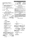
1
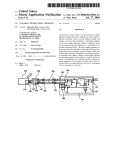
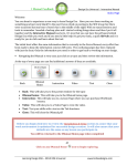
USOO8924708B2
(12) United States Patent
(10) Patent No.:
Yoffe et al.
(54)
US 8,924,708 B2
(45) Date of Patent:
SECURITY SWITCH
(58)
*Dec. 30, 2014
Field of Classi?cation Search
CPC ....... .. G06F 21/30; G06F 21/55; G06F 21/70;
(71) ApplicantszSimon Yoffe, Givat Shmuel (IL); David
G061; 21/82
YOffe’ GM“ Shmuel (IL)
USPC ........................................................ .. 713/152
(72) Inventors: Simon Yoffe, Givat Shmuel (IL); David
see apphcanon ?le for complete search hlstory'
Y ff G' t Shm 1 IL
0 6’ Iva
ue ( )
(*)
Notice:
(56)
References Cited
Subject to any disclaimer, the term of this
U S PATENT DOCUMENTS
patent is extended or adjusted under 35
' '
U-S-C- 154(b) by 0 days-
7,992,024 B2
This patent is subject to a tenninal dis_
2011/0131639 A1
Clalmer-
OTHER PUBLICATIONS
(21) APP1~ NOJ 13/969-1748
Rabiul Islam, Anil Sabbavarapu, Rajesh Patel, Manish Kumar, Jeff
_1 d
(22)
8/2011 Islam etal.
6/2011 Buhler et al.
Nguyen, Binta Patel, Amrish Kontu, “Next Generation Intel®
F1 6 '
Ang' 19’ 2013
(65)
ATOMTM Processor Based Ultra Low Power SoC for Handheld
Prior Publication Data
Applications”, IEEE Asian Solid-State Circuits Conference, Nov.
8-10, 2010, Beijing, China.
US 2013/0340069 A1
Dec. 19, 2013
Related U_s_ Application Data
Primary Examiner * Mohammad W Reza
(63) Continuation-in-part of application No. 13/020,042,
g4) fliotzqqugen? orlgrrgli Nathan&ASSOCIates patent
?led on Feb. 3, 201 1, now Pat. No. 8,522,309, whichis
a continuation-in-part of application No. 11/741,751,
?led on Apr. 29, 2007, now Pat. No. 8,090,961.
(60) Provisional application No. 60/881,510, ?led on Jan.
22 2007
’
'
'3
(57)
enac em
a an
ABSTRACT
syStem and I-nethOd for seem-mg a perspnal deVICe that
1ncludes a deV1ce core and a peripheral deV1ce from unautho
rized access or operation. The system comprises an isolated
.
(30)
gen 5
.
.
.
.
switch, included fully or partially within an envelope of the
Forelgn Apphcatlon Pnonty Data
personal device. The isolated switch cannot be affected in its
operation by either the device core or the peripheral device.
Feb. 5, 2010
(51)
(52)
(RU) ................................ .. 201000159
The switch may be Operated by an authorized user of the
P ersonal device either P reemP_tivel y or in _ res P onse to_ a
Int. Cl.
H04L 29/06
(2006 01)
detected threat. In some embodlments, the 1solated sW1tch
G06F 21/30
(201501)
includes an isolated controller which can send one or more
G06F 21/55
(201501)
signals to the peripheral device and/or part of peripheral
G0 6F 21/70
G0 6F 21/82
(201501)
(2013'01)
'
device. In some embodiments, the isolated switch includes an
isolated internal component and an isolated external compo
nent, both required to work together to trigger the isolated
switch operation. In some embodiments, the isolated switch
US“ Cl“
CPC ~~~~~~~~~~~~~~ ~~ G06F 21/30 (201301); G06F 21/55
(2013-01); G06F 21/70 (201301); G06F 21/82
includes an isolated disconnector for connecting and discon
necting the device core from part of the peripheral device.
(2013.01)
USPC ........................................................ .. 713/152
20 Claims, 16 Drawing Sheets
Personal Device
56
Device core
100
Isolated switch 102
lsolated User input
400
Logic
User Input
components
Peripheral Device
1 04
402
US. Patent
Dec. 30, 2014
Sheet 1 0f 16
US 8,924,708 B2
FIG. 1
Device core
100
, 7‘
Personal Device
50
V
Isolated switch
Peripheral Device
102
1 04
US. Patent
Dec. 30, 2014
Sheet 2 0f 16
US 8,924,708 B2
FIG. 2
Device core
100
Personal Device
52
Isolated switch 102
i
Isolated disconnector
200
t
Peripheral Device
1 04
US. Patent
Dec. 30, 2014
Sheet 3 0f 16
US 8,924,708 B2
FIG. 3
Personal Device
54
100
Device core
T
Isolated switch 102
swltCh MOde
Indicator
300
4* Isolated disconnector 200
T
l
Peripheral Device
1 O4
US. Patent
Dec. 30, 2014
US 8,924,708 B2
Sheet 4 of 16
FIG. 4
Personal Device
56
100
Device core
Isolated switch 102
Isolated User Input
400
Logic
l
/
User Input
components
Peripheral Device
104
402
US. Patent
Dec. 30, 2014
Sheet 5 0f 16
US 8,924,708 B2
FIG. 5
Personal Device
58
1 00
Device core
Isolated switch
1 02
200
Isolated disconnector
1105:“ user Input
\
User
components
Input
Peripheral Device
1 04
400
US. Patent
Dec. 30, 2014
Sheet 6 0f 16
US 8,924,708 B2
FIG. 6
Personal Device
60
_
Dewce core
/.
R/
‘1
‘
I
.
‘
//
/I’
l’/
l/
100
,I
.//
//
isolated switch
200
_
isolated dlswnneotor
400
1240le User Input
Input Mode
Logic
‘
Indicator
l
\
\_
\vl
User Input
components
Peripheral Device
1 02
104
402
500
US. Patent
Dec. 30, 2014
Sheet 7 0f 16
US 8,924,708 B2
FIG. 7
Personal Device
62
Device core
100
Isolated switch
102
200
Isolated disconnecth
limited
user Input
og1c
400
communication
components
602
Sensor corn onents
p
600
user Inpm
components
402
Peripheral Device
1 04
US. Patent
Dec. 30, 2014
Sheet 8 of 16
US 8,924,708 B2
FIG. 8
Personal Device
Device core
64
100
500
Isolated switch 102
Input Mode
Indicator
300
200
SWItCh Mode
1501ate d disconnector
IndlC?tOT
Isoluted User Input
Loglc
400
Communication
components
602
Sensor components
600
User Input
components
402
Perlpheral DeV1ce
1 04
US. Patent
Dec. 30, 2014
Vd
Sheet 10 0f 16
US 8,924,708 B2
Vd
1)—
To clrumno be
l1
To “Hummus
Immune“
l1
KK
I
Keya
lnmrupten
LR2
KK
.
s
m“: >
-
J33“:
LED %
LED
thRI!
:;
122
i
m
:
F|G_ 10
FIG. 11
ii“. M 1
.
\
Key5
E
3
T
0N5
5
T
.
7
_ Reset Data 4-_
W
,__
‘—L —
Q
Mn M a
LZD" °
\—
L1
lb
.
Tucimunstobe
imelupied
94
O
FL6
KeyA
0N4
Vd
Clock
R1
11 §
2
\_._._.
_._._.
.__
I 7
7
7
77
0°"
\_ Ret Data
-
Q2
Key3
Vd
6
_
Q
L
F|_5
0N3
Clock
'9
i
T
dip
/
km
T
4? Reset Data
-
'
K2 2
amaln
_|
Keys
—u\— 6
FL4
0N2
y
L2
—’VV\/—
“PM,” 9.“
12
%
4
[
Q
@W
R2
2‘
m
Coil
Clock
|
;
g
A;
1%
Reset new
I22
_
.
“W1
Q
0N1
Vd
Q
FIG. 12
Clock
i
FLa
US. Patent
Dec. 30, 2014
Sheet 11 0f 16
US 8,924,708 B2
Security
Sw'rtch
_(____l.._-,----IQ---4%I\--_<____¢__¢_____§__+__
Mode1+2
Mode2
D1
_.____?__¢!>___?__4!-___ Mode1
_4;____¢__¢_>____'p--q!_\---
""mflgm'“
Normal Mode
Op?m
Voc or Grd
Y
m
H
:[l
Audiolmuflm
_,
'D
EH5
u
— \—l —>
.
vnn
Transoelver
Camera Module 5)
u
I
I
‘
i
Opinn
Camera IC
-
i
V
CPU
DCZ
Memory
SIM Card
Graphic LCD
\
GPS
Receiver
Keypad
EH5
EH}.
V
US. Patent
53
Dec. 30, 2014
Sheet 13 0f 16
100
102
700
104
FIG.15
US 8,924,708 B2
US. Patent
Dec. 30, 2014
1‘55
Sheet 14 0f 16
174 173 172
PH1
FIG. 16
US 8,924,708 B2
US. Patent
175
Dec. 30, 2014
Sheet 15 0f 16
174173172
EH1
FIG. 17
US 8,924,708 B2
US. Patent
Dec. 30, 2014
Sheet 16 0f 16
Figure 18
US 8,924,708 B2
US 8,924,708 B2
1
2
SECURITY SWITCH
means such as phone-lines, cables, a wireless LAN, Blue
CROSS REFERENCE TO RELATED
APPLICATIONS
munication means can be used to retrieve private information,
tooth, etc, which only increases the security risk. These com
audio/video information, user location information (track
where user is located when personal device is using out com
munication) or transmitted information, and can be used for
transmitting data on the user’s behalf without his/her knowl
This application is a Continuation in Part of US. patent
application Ser. No. 13/020042, titled “Security Switch” and
?led Feb. 3, 2011 (now US. Pat. No. 8,522,309), which was
a Continuation in Part of US. patent application Ser. No.
edge.
11/741,751 titled “Security Switch” and ?led 29 Apr. 2007,
which claimed priority from US. Provisional Patent Appli
components such as a microphone, earphone(s), speakers,
cation No. 60/881,510 ?led 22 Jan. 2007. This application
further claims priority from Russian patent application No.
location. Devices with permanently installed or accessory
Devices with permanently installed or accessory sensor
camera, etc, are able to capture the information at a user
communication components such as a modem, a LAN
201000159 ?led 5 Feb. 2010, now allowed as EAPO patent
adapter, a wireless LAN adapter, Bluetooth, GSM, etc, are
No. 013885. All of the abovementioned patents and patent
applications are incorporated herein by reference in their
able to transmit information and may reveal the user location.
When signals are transmitted from the user location, the
transmission can be used for tracking the user location. Com
entirety.
ponents of a device/appliance that are controlled by software
and electronic switching devices may be controlled by an
TERMS
20
Authorized user4owner or permitted operator of a personal
device.
unauthorized user even if they were disabled earlier by the
authorized user. The components can be controlled without
the user noticing the change in mode of operation. For
example, a mobile phone may look “switched off” but may
Unauthorized useriany user or software that does not have
still be functioning or even transmitting, making a call or
an explicit permission to operate the personal device.
Unauthorized acces siany attempt of an unauthorized user to 25 sending an SMS on the user’s behalf, or capturing private
conversations around its location.
access or operate a personal device
Local authorized or unauthorized users can easily modify
False indication/noti?cationian indication showing one
state, while another “real” state is different.
the software operating the personal device, thereby causing a
security breach, e.g. by downloading a virus-affected soft
Hooked componentia component connected in parallel with
other device(s) to the same input element, in such way that
both devices can operate together, but the hooked compo
30
common: on one hand it is much easier than hardware modi
?cation, and on the other hand it is much harder to verify such
nent is isolated from the other device(s).
“Man in the middle”ia component logically placed between
a modi?cation, or notice unwanted change.
At present, the problem of unauthorized access is handled
two other components and which can control the informa
tion passed between the two other components.
Secure Inputian input readable only to a permitted compo
35
by different types of security software such as ?rewalls, anti
virus programs, anti-spyware programs and security systems.
However, each new software security system is eventually
overcome by new hacking methods, viruses, worms, Trojans
40
between security providers and unauthorized users. In
essence, software security is hard to implement and/or prove.
Even if the theoretical model of the security is proven, there
may still be a mistake or bug in the implementation that
allows a break in the security. Consequently, software secu
rity solutions cannot be trusted.
Hardware security solutions are known and include:
devices used to isolate telephone lines in order to prevent
unauthorized capture of audio information from phone user
(see US. Pat. No. 5,402,465 and US Pat. Application No.
20050271190); data line switches for computers that discon
nect a computer line physically from the Internet, working in
manual and/or automatic mode (US Pat. Application No.
20030062252); a power off method for a wireless peripheral
device, which terminates power to all parts of the wireless
device except the control chip by a certain operation on a
connect button (US Pat. Application No. 20050009496); a
switch that powers-on a PDA in response to the stylus being
nent, meaning that the input of the permitted component
cannot be revealed by others components.
Internalienclosed within an envelope or surface of the per
sonal device or positioned at least partially on the surface
and other threats. This creates an endless competition
of the envelope of the personal device.
Extemaliseparate from a personal device but which can be
connected to the personal device or plugged into the per
sonal device.
Isolated switchia switch that cannot be operated or affected
by any entity or factor except an authorized user.
45
Independent operationian operation that cannot be affected
by any entity or factor except an authorized user.
Isolated controlleria controller that cannot be operated or
affected by any entity or factor except an authorized user.
50
FIELD AND BACKGROUND
Embodiments disclosed herein relate to the security of
personal communication or computing devices which com
municate with other devices which use software for opera
55
tion. Personal software operated devices or appliances (here
inafter “personal devices”) such as mobile phones,
removed from the PDA’s stylus holder and, selectably, pow
ers-off the PDA in response to the stylus being replaced into
IP-phones, pocket PCs, PDAs, laptop computers, desktop
computers and network switches, use a variety of hardwired
ware update. This scenario of software modi?cation is very
60
or wireless communication means for communication with
other devices. A remote unauthorized user can adversely use
these communication means to try and break open the per
sonal device security and obtain personal and other informa
the PDA (US. Pat. No. 6,233,464); a mobile phone with two
input modes, whereby a switch of input modes is attained by
changing an electrical connection between the main printed
circuit board (PCB) in the phone and the front and back PCBs
tion on the personal device user or owner, or to perform 65
(U .S. Pat. No. 7,031,758); the NetSafe Computer Security
Switch, whichuses a simple physical switching technology in
unauthorized operations on the user’s behalf. A single per
a way that allows a computer or group of computers to quickly
sonal device may have a number of different communication
and easily block a communications signal from entering the
US 8,924,708 B2
3
4
computer(s) and restart the signal without any software and
trical, the security switch is isolated electrically, i.e. com
pletely separated electrically from other elements or compo
nents of the personal device.
The principle of operation of the security switch disclosed
herein relies solely on manual disconnection (or connection)
of audio/video/communication or power supply components
without the need to power down, reboot, or run software on
the computer(s) (US Pat. Application No. 20040243825); a
wireless button for a laptops, offered by the Hewlet Packard
Corporation in its line of Pavilion laptops (hereinafter the
“HP wireless button”), which enables or disables all inte
in the personal device in order to avoid unauthorized access to
grated wireless components in the laptop (e.g. WiFi and Blue
the information or personal device. This provides full isola
tooth), and a wireless light that indicates simultaneous the
computer’s overall wireless state (enabled or disabled); the
portable electronic device that disconnects a receiving
antenna from the duplexer of a mobile phone (US Pat. Appli
tion even in cases of full access to the device software or
remote access to electronic components of the device, in the
sense that an unauthorized user is not able to connect electri
cal circuits that are switched off manually, and a bene?ciary
side effect of power saving in case of power supply discon
nection.
Two main modes of operation are provided: “mode
cation No. 20040203536A1).
All existing protection solutions suffer from one of two
disadvantages: either the switch is “external” and can there
fore be tampered with by an external factor, or the switch is
”imanual switching by an authorized user (or simple
“user”) for preventing capture of audio/video information
from the user; “mode 2”imanual switching by the autho
internal but not fully isolated from the device itself (and
therefore can be manipulated by the software of the device).
Consequently, existing solutions cannot provide simulta
neous temporary protection from audio/video information
20
capture, cannot provide simultaneous temporary protection
rized user for preventing unauthorized determination of the
user location or capture of other information. In mode 1, the
user can receive visual information (for example incoming
from both audio/video information capture and unauthorized
calls, SMS, memos, ?les, etc) yet is protected from being
access and user location\device location and cannot provide
listened to, recorded or visually captured by unauthorized
secure security mode exit or prevent capture of the logic
required for exiting the security mode. Existing internal
25
tion cannot be discovered by any means and no information
switches cannot provide prevention of false noti?cation about
the device security mode in a device with already broken
transfer is possible. There is also a possibility to combine
modes 1 and 2 into a “combined mode”. Note that mode 2 is
software security, i.e. in a state in which an unauthorized user
not a substitute for mode 1, since in case of unauthorized
gains access or control of the personal device despite software
30
protection solutions.
35
SUMMARY
40
Embodiments disclosed herein disclose hardware security
case of full access to the device software or by remote access
45
mation, user location information or transmission informa
means, referred to as “security switch” or “isolated switch”,
50
means that the control elements of the switch do not have any
external communication capability and are protected from
remote operation/manipulation.
In some embodiments a security switch disclosed herein is
a component having (a) control elements that are not con
nals, even in cases when the device security is already broken.
The protection is based on an operation that can be performed
only by an authorized user (manual disconnection of the
relevant components) and that cannot be performed by the
60
control elements in (a).
The security switch may be mechanical (i.e. electrical con
software of the device or by the device itself. The protection
is further based on the principle that the operation is not
known to the software of the device or to the device itself.
In some embodiments, there is disclosed a system for
securing a personal device that includes a device core and a
peripheral device from unauthorized access or operation, the
tacts switched mechanically) or electronic/electrical. When
mechanical, its control is already isolated because it can be
operated only by manual physical operation of the user, not by
connected, information cannot be obtained by an unautho
rized user. When all components capable of transmitting a
signal from or to a user’s device or appliance (i.e. RF, WiFi,
Bluetooth, NFC, and LAN) are disconnected, the user loca
tion and other private information cannot be obtained by an
unauthorized user. Embodiments of systems and methods
disclosed herein are not concerned with software security, but
devices capable of capturing information or transmitting sig
55
be isolated and shielded, or that are decoupled in such a way
the device itself. A mechanically operated switch should not
have an electrically operated bypass. When electronic/elec
capable of capturing audio/video informationiie. micro
phone(s), headphone(s), speaker(s), and camera(s) are dis
with protecting certain private information by disabling
nected electrically to an environment from which they should
that both electrical and magnetic ?elds cannot in?uence their
operation, and (b) switching elements that cannot be con
nected, disconnected or bypassed by elements other than the
to disconnect components that can capture audio/video and
user input information or transmit signals from/to the user’s
personal device. When an electrical circuit is broken manu
ally, it cannot be reconnected by an unauthorized user even in
to an electronic personal device. When all components
tion and for performing operations securely. The hardware
are internal to the personal device and is isolated, both “inter
nal” and “isolated” being de?ned above. The “isolation” also
rarily change the mode of operation when in need of privacy
and wants to avoid possibility of spying after him/her by
capturing his/her audio/video information or tracking his
location. A manually operated security switch allows the user
tages.
solutions that overcome the problems of hardware and soft
ware security solutions mentioned above. They provide a user
of a personal device with hardware means for protecting
information such as private information, audio/video infor
access; audio/video information canbe captured and stored in
the device memory, then transmitted after the user exits mode
2.
The switch allows the user of a personal device to tempo
There is therefore a widely recognized need for, and it
would be highly advantageous to have a simple internally
isolated hardware security solution for the users of the above
mentioned personal devices that does not suffer from the
above mentioned software and hardware solution disadvan
access to his personal device. In mode 2, the communication
to the device is completely disconnected, so the device loca
65
personal device having an envelope or surface, the system
comprising an internal isolated switch having operating func
tions that cannot be affected by either the personal device core
US 8,924,708 B2
5
6
or by a peripheral device, wherein the isolated switch
includes an internal component located within the envelope
or at least partially on the surface of the personal device and
wherein the isolated switch internal component is selected
FIG. 5 shows yet another embodiment of a personal device
with a security switch disclosed herein;
from the group consisting of a mechanical element without an
FIG. 7 shows yet another embodiment of a personal device
with a security switch disclosed herein;
FIG. 8 shows yet another embodiment of a personal device
with a security switch disclosed herein;
FIG. 9 shows an example of an electro-mechanical imple
mentation of an isolated switch disclosed herein;
FIG. 10 shows an example of an electrical implementation
of an isolated switch disclosed herein;
FIG. 11 shows another example of an electrical implemen
tation of an isolated switch disclosed herein;
FIG. 6 shows an embodiment of a personal device with an
input solution for security switch disclosed herein;
electrically operated bypass and an electronic/electrical ele
ment separated electrically from elements or components of
the personal device.
In some embodiments, the isolated switch includes an iso
lated disconnector for connecting and disconnecting the
device core from part of the peripheral device. In some
embodiments, the isolated switch includes an isolated inter
nal component and an isolated external component, wherein
the isolated internal and external components trigger together
the isolated switch operation.
FIG. 12 shows an example of an electrical/ electronic
20
implementation of an isolated switch disclosed herein;
FIG. 13 shows an example of an electro-mechanical imple
mentation of an isolated switch disclosed herein;
FIG. 14 shows an example of an electro-mechanical imple
mentation of isolated switch disclosed herein;
FIG. 15 shows yet another embodiment of a personal
device with a security switch disclosed herein;
FIG. 16 shows an example of electrical/electronic imple
mentation of an isolated switch with partial disconnection
25
disclosed herein;
In some embodiments, the peripheral device may be a
sensor device, for example a microphone, earphone(s),
speakers, camera, etc. In some embodiments, the peripheral
device may be a communication device for example a
modem, LAN adapter, Wireless LAN adapter, Bluetooth
device, GSM device, RF device, etc.
In some embodiments, the peripheral device may be a user
input device for example a keyboard, touch screen, etc. In
some embodiments, the peripheral device may be a USB
device, for example a USB “key” or mass storage device
(MSD), a USB Bluetooth device, a USB wireless device or
any other known USB device.
In some embodiments, the peripheral device may be a
non-USB MSD, a display, a memory, etc.
In some embodiments there is provided a method for secur
ing a personal device that includes a device core and a periph
FIG. 17 shows an example of electrical/electronic imple
mentation of an isolated switch with isolated controller dis
closed herein;
FIG. 18 shows an example of electrical/electronic imple
30
mentation of an isolated switch with external and internal
components for mutual triggering of operation disclosed
herein.
eral device from unauthorized access or operation, compris
ing the steps of providing an internal isolated switch having
operating functions that cannot be affected by either the per
sonal device core or the peripheral device, wherein the iso
lated switch includes an internal component located within
the envelope or at least partially on the surface of the personal
DETAILED DESCRIPTION
35
device, wherein the isolated switch internal component is
selected from the group consisting of a mechanical element
without an electrically operated bypass and an electronic/
electrical element separated electrically from elements or
components of the personal device, and wherein the isolated
40
The invention discloses security systems and devices for
protecting personal devices and their users from unauthorized
access, operation, identity theft or information theft. In par
ticular, the invention discloses a security switch that provides
total protection of information related to the personal device
or a user of the device. In the following description, like
elements appearing in different ?gures are numbered identi
cally.
switch is con?gured to act as man in the middle between the
FIG. 1 shows a ?rst embodiment 50 of a personal device
device core and the peripheral device, and using the isolated
switch to protect the device from unauthorized use or access. 45 with a security switch disclosed herein. Personal device 50
includes a device core 100, an isolated switch 102 and at least
BRIEF DESCRIPTION OF THE DRAWINGS
one peripheral device 104. The dotted arrows indicate an
Reference will be made in detail to preferred embodiments
disclosed herein, examples of which may be illustrated in the
accompanying ?gures. The ?gures are intended to be illus
50
optional direct connection between device core 100 and
peripheral device 104 and/or between device core 100 and
isolated switch 102. Device core 100 operates by software
and may include one or more controllers (e. g. central process
trative, not limiting. Although the invention is generally
ing units (CPUs)), one or more memory units and one or more
described in the context of these preferred embodiments, it
should be understood that it is not intended to limit the spirit
and scope disclosed herein to these particular embodiments.
The structure, operation, and advantages of the present pre
ferred embodiment disclosed herein will become further
power management modules.
A peripheral device 104 may include one or more commu
55 nication components, and/ or one or more sensor components,
and/or one or more user input components, and/or one or
more other peripheral devices. Each of these will be shown in
following ?gures. The communication components may
apparent upon consideration of the following description,
taken in conjunction with the accompanying ?gures, wherein:
FIG. 1 shows a ?rst embodiment of a personal device with
a security switch disclosed herein;
FIG. 2 shows another embodiment of a personal device
with a security switch disclosed herein;
FIG. 3 shows yet another embodiment of a personal device
with a security switch disclosed herein;
FIG. 4 shows yet another embodiment of a personal device
with a security switch disclosed herein;
include wireless communication components or wired com
60
munication components (e. g. WiFi, RE, Bluetooth, NFC,
LAN, and modem). The sensor components may include
audio components, video components (e.g. a microphone,
speaker or camera). The user input component may include a
keyboard or a touch screen. The other peripheral devices may
65
include a USB or non-USB MSD, a display or a memory.
In this and following embodiments and implementations,
the peripheral device may be for example as USB device, i.e.