1
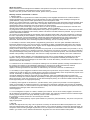
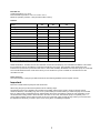
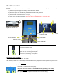
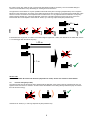
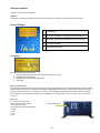
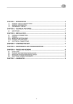
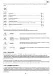
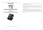
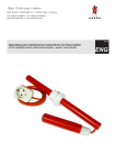
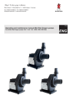
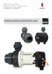
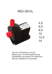
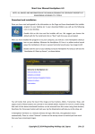
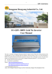
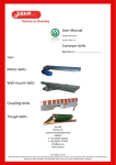
Blue Eco 240/320/500 User Manual About this manual Please read the manual carefully before installation and operation of the pump to avoid questions and problems. Operating the pump is considered as acknowledgement that you have read the manual. In the case you didn’t catch on the manual, please contact your dealer. Warranty claims & claims based on defects 1. Warranty claims 1.1 We are liable that our goods are free of faults until passing of risk. Negligible deviations from conditions stated or marginal impairment of serviceability are to be disregarded. The state contractually owed, durability and usage of the goods delivered, comply with the written specifications, product descriptions and/or manuals. Any further statements, in particular, preliminary talk, advertisement and/or referenced industrial standards shall be only integral part of the contract when written. Our expressly stated characteristics of the product apply. Guaranteed characteristics made by third parties cannot be accepted. The characteristics expressly stated in this manual apply. If the goods are to be used for purposes other than intended, the customer must carefully check usability and reliability on his own responsibility. We are not liable for any usage other than expressly stated. Manipulations of the pump, the impeller, the electronics as well as the trial to hack or read the firmware immediately voids warranty. Please note that the controller software is protected. Trying to read this software will activate its deletion. Any customer is solely responsible for the intended usage of his BLUE ECO PUMP. Using this manual does not absolve the user’s responsibility for safe installation, operation and maintenance. By the use of this manual the customer accepts that the manufacturer cannot be held liable for material and personal damages arising from usage of the product. In particular, damages arising from improper tubing, lack of maintenance, calcinations, as well as absorbed foreign substances, like sand/rocks, which will damage impeller and bearings, are not covered by warranty. 1.2 Our liability for defects is strictly limited to supplementary performance. At its own option Estrad BV shall mend or replace the defective goods. In the case of rejection, impossibility or failing of supplemented performance the customer may lower the price or negotiate the contract. Higher costs for supplemented performance arising from the fact, that the customer moved the goods to a place other than his primary location will be charged. Warranty is limited to the pump itself. In no event will be liable to the purchaser, or to any user of Estrad BV products, for any damages, expenses, lost revenues, lost savings, lost profits, or any other incidental or consequential damages arising from the purchase, use or inability to use Estrad BV products, even if Estrad BV has been advised of the possibility of such damages. The customer is solely responsible for a standby unit in case of malfunction. 1.3 The Customer shall be obliged to check the delivered goods, also for product reliability, immediately and notify the supplier in writing of any discrepancies. Concealed damages have to be reported immediately after detection. The customer has to report transport damages to the carrier within 24 hours after delivery. No observance of due diligence will void the customers claim warranty. 1.4 Furthermore we are not liable for consequences resulting from not intended operation, handling and maintenance of the goods by the customer or his subsidiaries, particularly for consequences resulting from thermal, chemical, electrochemical or electrical effects, as well as infringements to the manual. The same applies, if the damage results from intervention or instructions by the customer, which are not affirmed by us. 1.5 Our liability for gross negligence is limited to claims arising from injuries of life, body and health, to claims from Product Liability Code as well as claims from culpably breach of important contractual duties, which compromise the purpose of the contract. Incidentally, our liability for gross negligent infringement of essential contractual obligations is limited to the typically incurring damages, which were predictable when the contract was concluded. Generally the customer takes full responsibility for damages arising from inappropriate operation of the goods. When returning any goods, the customer has to care about break-proof packing. The customer is liable to the full extend for damages arising from an inappropriate packing. 1.6 Warranty claims against us are limited to 1 year after delivery of the goods to the purchaser. The same applies for claims of compensation for whatever legal ground. The restriction for the period of limitation does not apply for fraudulent concealment of a defect, for claims based on the product liability code as well as damages arising from injuries to life, body and health and for damages, which result from intention or coarse negligence. 1.7 If our investigations or repairs on a defect, claimed by the customer, turn out to be coarsely negligent, we reserve to ask an adequate compensation for our investigations and/or repairs. The customer is entitled to refuse an essential repair and may request the return of the pump. Basically, we ask a costs compensation, if the inspection of a defect turned out to be caused by the customer. 2. Spare parts Our obligation for stocking/delivery of spare parts is limited to a period of 5 years after delivery. The prices of our price list apply for spare parts. 3. Disposal We offer free disposal and recycling of all our products covered by the “Electrical and Electronic Equipment Act”, which have been delivered after 2005, August, 13th within Germany. If the customer decides to arrange the disposal himself, he accepts the duties according the legal requirements on his own expense and indemnifies us from the take-back obligation stated in § 10 section 2 of the “Electrical and Electronic Equipment Act” and coherent claims of third parties. 2 4. The manufacturer is entitled to initiate hard- and software modifications of the product without notification, as long as operation, reliability and quality of the pumps were improved. No claims can be made, when e. g. design, functionality or power of the pumps were changed fundamentally. It is assured, that the guaranteed specifications remain unmodified. CE-Manufacturer’s declaration The manufacturer ensures and declares that the products of the BLUE ECO PUMP series are in accordance to the following EWG regulations, when installed and used according the manual: Machine (98/37/EG) Electromagnetic Compatibility (89/336/EEC)/(73/23/EWG (95) EN ISO 12100 Norm EN 61000-6-2 Electromagnetic Compatibility EN 61000-6-3 Electromagnetic Compatibility EN 60335-1:2002 Household and similar electric devices EN 60335-2-41:2003 Household and similar electric devices; typical requirements for pumps. EN 60335-2-55:2003 Household and similar electric devices; typical requirements for electrical devices like used in tanks and (garden) ponds. EN 50366:2003 Household and similar electric devices. Electromagnetic fields. Procedures for evaluation and measurement. EN 55014-1:2006 Electromagnetic compatibility. Requirements for household devices, electric tools and similar devices; emissions. EN 55014-2:1997 Electromagnetic compatibility. Requirements for household devices, electric tools and similar devices. Immunity; product group standard. 3.1. Manufacturer Estrad BV Westeinde 46 7711 CL Nieuwleusen 3.2. Production All BLUE ECO PUMP series pumps and accessories are made in Netherlands and China. Dear customer, Thank you for choosing BLUE ECO pumps. This pump has been developed under the newest technology available with the most modern and reliable parts. Blue Eco pumps use True Sine Wave technology to provide the most energy efficient technique. Please read this manual carefully before using the pump. Symbols ! CAUTION – HIGH VOLTAGE IGNORING THIS INSTRUCTION MAY HARM USER AND/OR ANIMALS. CAUTION IGNORING THIS INSTRUCTION MAY DAMAGE THE PUMP AND/OR OTHER DEVICES ATTACHED. Not intended use This manual is intended to give you brief information about the device. The user, installer or maintenance personal, is solely responsible for the strict adherence of all instructions made in this manual. The BLUE ECO was manufactured according state-of-the art technology and current safety regulations. Nevertheless this device may involve risks for life and physical condition if not used as intended or if safety regulations were ignored. If not used as intended, our liability expires as well as the general operating license. Children, youth below an age of 16 as well as persons who may not recognize possible risks or who are not familiar with this manual must not use the device for safety reasons. Please keep this manual safe and hand out in the case of change of proprietor. The combination of water and electricity may severely harm life and physical condition if the device was not connected properly or used inappropriate. 3 Do not use the device as long as persons remain in the water! Unplug all devices in the water before touching the water! Check the specification of the mains against the electrical specifications on the package or the label of device. Make sure the device is connected to a fault current detection switch with a fault leakage below 30 mA (DIN VDE 0100T739) Use the device only if plugged into a wall plug installed according to regulations). Keep the power plug and all connections dry! Install cables dry and save to avoid damage. DO NOT CUT OR TRIM THE CABLE OR PLUG OF THE DEVICE; CLAIMS AND WARRANTY EXPIRE IMMEDIATELY!. ! Only use cables, adapters, installations, extension cords or power cables which are designed for outdoor use (DIN VDE 0620) and with a proper cable diameter. Do not pull or carry the device on the cables! In the case of a defective cable or housing, the device must not be used! Protect cables and accessories against heat, oil, UV light and sharp objects. The manufacturer cannot be held liable for damages resulting from unintended or inappropriate use or negligence of the user or installer. Damages to the power plug or the housing remains the device unusable. Repairs are impossible due to the fact that the cables were cast into the housing. Keep the connectors dry. In the case the connector got wet or humid it must be rinsed in demineralised water and must be carefully dried by a trained service person. ! Generally the pump must be cleaned carefully before put out of operation. At return of service check clearance of the impeller. If the impeller cannot be moved the pump must be disassembled and cleaned. DO NOT unplug the power plug while operating the pump and the controller. This may result in severe damage of the internal electronics and dangerous hazards due to grounding problems. The controller must be connected to a safety fault current detector (30mA) and a properly installed wall plug. Do not modify or replace any cables. Electric installations on garden ponds must be in accordance with national and international regulations, guidelines and engineer standards. Never open the housing of the device or attached parts if not explicit stated in the manual .Use original spare parts and accessories only. Repairs must be executed by trained service persons only. DO NOT pump any liquids beside water. In the case of questions or problems, for your own safety, contact trained service persons. ! Unplug the pump from main power before service and/or maintenance! Applications The BLUE ECO pump was designed for fresh-, brackish- or salt water, or other low viscosity liquids which are neither explosive nor aggressive or oily. The pump may be used for clean water and in a limited way also for contaminated water. The pump is not intended for water with coarse debris. Particles should not be larger than 0.8 mm. Basically the pump is intended for use with „clean water” without solid particles which may damage the bearings, like, for example sand and pyrolusite after the treatment of ponds with potassium permanganate. Warranty does not apply for damages resulting from above described particles. The bearings of the pump are milled spirally to evacuate particles larger than 0.8 mm. The bearing plate contains enough space for a filter. The filter must be cleaned regularly regardless the degree of soiling. A special amount of water is flushing the pump housing to ensure long term operation of the pump. To decrease the flow rate in the housing, perfectly close the plate and adjust to the smallest dot on the plate. Now the bearing lubrication by water is very low. The BLUE ECO Pump is generally used for filter systems of ponds or pools and /or for brooks and cascades. The pump is not self-priming, so for use above the water surface a check valve must be installed to the pump’s inlet. In this case the pump must be water filled before operation. Pre-filter example 4 Intended use Liquid temperature: 0 to +40°C. Environmental temperature: from 0 °C to max. +50 °C Maximum operation pressure: 2 bar (20 meters water column) Features Model 240 Voltage Induced power P1 240 watt Nominal power 320 500 110/ 220 Volt 50/60 Hz P1 320 watt P1 500 watt P2 216 watt P2 280 watt P2 473 watt Efficiency 90% 90% 90% External controller yes yes yes IP68 yes yes yes Cable 10m 10m 10m Digital display yes yes yes Suited for dry & wet applicationa yes yes yes 2½” male thr. 2½” male thr. 2½” male thr. / 110mm Inlet Outlet 50/63mm 50/63mm 2” male thr. Weight in kg 3 4 7 Warranty pump 2 2 2(5) yes yes RPM 300 ‐ ±2850 yes For more specification refer to the type plate. Model identification: The Blue Eco 240 and 320 Watt use the same model pump, the controllers are different. This means that a model 240 can be controlled by a 320 watt controller and vice versa. The type plate of the 320 shows a 500 indication box (at the time of production there was no 320 model available). Model 500 uses the same pump as model 900. The controller determines the model. In the future you can decide to buy a 320 controller for a model 240 or a 900 controller for a 500. Noise emission: The noise emission of the pump is within the limits of the machine guidelines of the European Council. Important Initial use of the BLUE ECO pump 240 watt & 320 watt. When using the pump for the first time please use the following steps: The blue Eco pumps use a flexible O-ring between the impeller and the pump house to obtain a optimum seal for maximum efficiency. This sealing ring must “run in” (under water!) for a while. When you switch the pump on for the first time you will see that at 1000 RPM (factory default setting) the power consumption is about 50 watt. Depending on the circumstances this will go back to about 25 watt in the next 1 to 24 hours. After that the pump is completely run in . A wrong setting operation cannot harm the pump. Every box comes with a bag of spare O-rings. When you have removed the impeller from the shaft you need to put in a new O-ring when re-installing the impeller. 5 Short Instruction The pump is driven by a DC-motor and, therefore, equipped with a controller. Check the following sequence when starting the pump: 1.) Flush the pump thoroughly to remove any residual disinfection fluids!!! 2.) Install the pump below the water surface (Pump is not self-priming). 3.) Interconnect pump and controller using the attached controller cable (check pins). 4.) Check the main power switch is set to „0” (OFF). 5.) Connect the mains cable to the controller and plug into a wall plug. 6.) Switch on the controllers power switch. The pump will run immediately! (after a 10 second delay) Power switch 0-10V connector Fuse Coded plug, fits only one way Controller cable 0-10V connector Power switch Controller cable Key Power cable 230 V Power cable 230 V Function Switching the pump on and off INCREASE PUMP POWER (when running) Higher flow-rate, more energy consumption DECREASE PUMP POWER (when running) Lower flow-rate, less energy consumption Switching the pump on and off: The pump is switched on and off with the „0/1“-switch. After switching on there is a 10 second delay countdown. After that, the pump slowly increases speed to the previous value set, while the flow rate is also updated. When switched off, the pump stops immediately. ▲ / ▼ keys: Use the ▲ / ▼ to set the power of the pump. This will also change the flow (l/h) and the energy consumption (W) and the RPM. The power can be set between 10 and 240/320/500 watt (depending on the model). The pump will always run on the set power. After a power break the pump will automatically return to the last setting. 6 INSTALLING If used in dirty water the pump requires a pre-filter as mentioned earlier in the manual. We recommend the use of 2- or 3/3 unions, for easy disassembly for pump cleaning or maintenance. Example 1 Suction side: 2-part unions with rubber ring for easy sealing (art.nr. AG287: 2½” x 63mm, see picture). Pressure side: a PVC 3 part Union (Ø63mm) can be glued on the pressure side. Do not glue straight socket fittings on the pump as this makes disassembly extremely complicated! The use of pieces of flexible is recommended to prevent vibration and resonation. (see example 2). Model 240/320 Example 2: Flexible fittings provide a vibration free performance and are very easy to remove. Suction side: a solvent ring 90mm x 2½” fem. thr. (art.nr. AB367) can be fitted with some liquid Loctite 5331 (art.nr. AK142) or Teflon tape. On this ring a flexible reducer fitting (90mm/3” to 63mm/2”) can be fitted (art.nr. FC146). On the pressure side you can put a 63mm/2” flexible fitting (straight socket “FC122” or a 90° bend “FC172”). The rubber feet underneath the pump will provide a complete vibration free performance. Example 3: Model 500 has a double suction side: 110mm outer diameter and 2½’ male threading. You can use a flexible socket for the 110mm connection (art.nr. FC128). For the threaded connection you can use a 2-part unions with rubber ring for easy sealing (art.nr. AG287: 2½” x 63mm) For de pressure side you can use a 3/3 PVC union Ø63mm x 2½” fem. thr. (art.nr. AB246) with teflon or Loctite 5331 (art.nr. AK142). Model 500 7 Assembly Attention: Read the manual carefully before installation of the pump. Damages resulting from non-observance are not covered by warranty. When unpacking the pump, check the parts for completeness and damages. Damages detected must be advised to the supplier within 8 days after purchase. It is possible that the pump is moist or wet after unpacking due to the fact that the pump had been tested before leaving the manufacturer. Before wrapping, the pump has been treated with a biodegradable disinfectant to eliminate possibly existing germicides. Therefore the pump must be rinsed thoroughly before operation. Check the pump for damage before putting into operation. A damaged pump must NOT be operated. Immediately contact your supplier! Putting the pump into operation in spite of visible damages will void warranty and manufacturers liability. Unplug the pump from the mains and make sure it cannot be operated. The pump must not be connected to the mains during the entire installation process. Never put your hands or fingers into the openings of the powered pump to prevent injuries. 1.1. Controller The controller unit can be installed indoor and outdoor. Do not expose the controller to direct sun light or heat (powerful lamp, radiator). Be sure there is enough air circulation. Keep all sides of the unit free for at least 10cm. >10 cm >10 cm >10 cm >10 cm 1.2. Pump The pump must be installed in a horizontal position. The pump must rest firmly on a flat and even surface. Install the intake line to the pump’s inlet (1) (see fig.). Make sure the pump can evacuate air from the outlet (2). At best, install the pump below the water level (3). The pump may be installed inside (4) as well as outside (dry) of the water (5). If operated outside, check for sufficient air circulation. Do not expose the pump to direct sunlight. Install the pump as close as possible to the location of water withdrawal, i. e. the intake line should be as short as possible. If the pump was operated above the water level (6) install a check valve to the pump’s inlet (7). In this case, the intake line of the pump must be filled with water. This kind of installation exposes the pump to dry run damages if the check valve doesn’t work correctly. Damages resulting from running dry are not covered by warranty. 3 6 5 4 7 2 1 1.3. Suction side (pump inlet) If there is not enough water, due to the resistance of the intake line the pump needs a lot of power and the electronics will heat up in the long run. The electronic circuit protects itself by powering down. If the flow rate of the pump decreases within a couple of hours or days, the reason might be the too high resistance of the intake line, especially on warm days. Try to enlarge the pipe diameter after the pump to a sufficient size for more pump capacity and and lower energy consumption. It is not allowed to let the pump run dry. It will lead to irreparable damage to the shaft and silicium carbide bearings. Especially when the pump is mounted above the water surface level (with a check valve) you have to be very careful about 8 this. When used in dirty water the use of a (previously described) pre-filter is necessary. The use of flexible fittings or unions is recommended for easy dismantling for cleaning and/or maintenance. The pipe work must be fitted in a way that possible mechanical stress (due to changing temperatures) have no negative influence on the pump house. Any tubing on the intake line must be 100% air tight. If a hose was used as intake line, make sure the hose is in accordance to the requirements for intake hoses. It is very important that the intake line on the pump head is primarily straight (min. 5 times the diameter of the inlet). This will increase the power of the pump, due to the laminar water flow on the impeller. Avoid short 90° bends, try to use long swept bends (less pressure loss). x5 = 5x ! If the intake line is longer than 10 meters or the intake height is higher than 1 meter, the diameter of the intake line must be 1 or 2 sizes bigger than the inlet of the pump. >10 m >1m Suction side: 2 ½“ male threaded / Ø110mm outer diameter (dependant of model). Suction line must be at least Ø75mm. 1.4. Pressure side (pump outlet) The pressure side must be at least the same diameter like the diameter of the pump’s outlet to avoid pressure drop, too high flow rates and noise to a minimum. At best increase the diameter of the tubing directly behind the pump to increase flow rate and save energy. ( ) Avoid short 90° bends, try to use long swept bends (less pressure loss). 9 If there is a chance of a blocked pump (e.g. closed ball valve), a bypass must be installed to the pressure line to ensure some water flow through the pump. Connection pressure side: 50/63mm or 2“ male threading (dependant of model) Flow Maximum flow – volume in pipe diameter: Pipe diameter [mm] 50 63 75 90 110 125 Optimal flow for minimum pressure loss[l/h] 8.000 14.000 20.000 29.000 43.000 55.000 Electrical connections– initial startup Compare voltage and frequency imprinted on the specification plate to the specifications of your mains voltage. The one who is responsible for the installation must check, if the voltage grounding was according to specifications. It’s also important to check, if the installation was secured by a sensitive fault current detection switch (30mA - DIN VDE 0100T739). The mains fuses should be stronger than the pump fuses. Fuse: Power 240Watt 320Watt 500Watt 900Watt 1500 Watt Pump fuse 1,2 ampère 1,6 ampère 2,5 ampère 6 ampère 10 ampère Mains fuse 4 ampère 4 ampère 6 ampère 10 ampère 16 ampère Overload protection The Blue Eco pumps were equipped with electric and electronic fuses for overload protection. If the impeller blocks, the motor stops. When blockage has been cleared the pump can be restarted again or it restarts itself where applicable. 10 General operation Operation and function of the display. Attention: The imprint on buttons and display may differ from the text in the manual, but the functions remain the same. Keys & Display 1 2 4 3 5 1 LCD Display 2 Run LED: This led is on during pump performance 3 Stop LED: This led is on when the pump has stopped 4 Increases the RPM 5 Decreases the RPM LCD Display 1 2 3 4 The display shows the following data: 1. Hour counter: shows how many hours the pump has been running. 2. RPM (Rotations Per Minute). 3. Wattage: the current energy consumption 4. Amperage External connections The external connection with RJ45 connector can be used to change the RPM. A 10volt signal triggers the maximum RPM (±2800). Please note: the 0-10volt signal cannot trigger a RPM setting lower than the current value. Example: the pump is running at 1500 RPM and the 0-10v connector sends out a low voltage that is below the 1500 RPM, nothing will happen. The moment the outgoing signal is higher than the 1500RPM, the 1500 RPM will increase. Use pin 2 and 5 of the RJ45 connector. Signal port 1 = Source current of 5 Volt 2= DC control current 0-10 volt 3= Program inlet TXD 4= Program in Program inlet let RXD 5= GND 6= NC 7= NC 8= NC 0-10V connection 25 11 Error messages When there are errors or changes occur the output to the pump will be stopped and the display will give an ALERT rd message. The 3 line in the display will indicate the error code. This is a list Wanneer er fouten ontstaan of veranderingen plaatsvinden zal de output naar de pomp gestopt worden en komt er ALERT in het display te staan. De derde regel geeft de foutcode weer hieronder volgt een index met fout codes Over Voltage Low Voltage Over Out Current P 2 P Short Circuit P 2 E Short Circuit Data Error All Data Initial User Data Initial Key Data Modified CT U Error CT V Error Power Supply ERR IPM Overheating Over In Current Pump Blocked Cable Error Unauthorized The DC voltage is higher than 400V, which may happened when pump speed down quickly without load. The DC voltage is lower than 220V, which may happened on the time of the power just on or off. The current of pump get too big suddenly, and controller stop output to protect the pump. There is a short circuit between two output phases. There is a short circuit between phase and earth. The data in eeprom get wrong, should initial all data to recover this error. All data in eeprom was initialized. User data in eeprom was initialized. Some important data in eeprom was changed. The current transducer on U phase is wrong. The current transducer on V phase is wrong. The input power is wrong. The temperature of controller gets too high. The current of input gets too big. The pump is blocked and controller can’t start it. The output cable connection is wrong. The software is unauthorized. Controller diagram PWM Signal Motor Currents DC Voltage Diagram of Pump Controller Maintenance Unplug the pump before maintenance. Blue Eco series are basically treated as low maintenance. In normal case maintenance is restricted to impeller checking for clogging. Remove potential objects from the impeller with a thin, spiky tool. A reduced delivery rate of the pump is generally caused by waste in the impeller. In the case of calcification (especially when used in salt water) remove the scale with a weak acid like vinegar. Avoid sidewise pressure to the impeller or the rotor. The pump can be completely disassembled for cleaning. The rear bearing can be easily removed by unscrewing of the bearing plate counter clockwise. Use an appropriate tool to move the shaft to the front, so the impeller unit can be removed much easier. In fresh water applications, calcification generally occurs before and after a complete pond filling. The dissolved lime scale will precipitate within 2 or 3 days. Use a M6-Allan key to remove the titanium screws (1), which mount the pump head to the motor housing. Now, the complete pump head can be removed. If necessary, remove the complete impeller from the 240/320 unit by pulling out the shaft after removing the O-ring. For the models 500/900/1500 you need to remove the nut on the impellers front. This will reveal 3 screws that also need to be removed. You can now remove the shaft. ! Be very careful, because the impeller is fixed to its position by a strong magnet. Releasing the shaft occasionally may hit the bearing resulting in severe damage. Do not underestimate the power of the magnets. If you lose grip the shaft will hit the rear bearing, which most likely will result in severe damage and, thus, in expensive repair costs... 12 After maintenance reassemble the pump in reverse order. Do not over tighten the screws, due to the fact that the threads in the case are made from plastic. The O-rings are made from silicone or EPDM/Viton, depending on the application. As spare parts, only use new and original O-rings with the proper thickness and hardness. Used O-rings slowly alter their hardness. Always replace with new parts if disassembled to prolong the life time of the pump. Silicone and EPDM/Viton ORings are resistant against acids and bases. Bearings The bearings of the 240 and 320 are based on silicium/ carbide (the hardest material after diamond). The front and back bearing are equal and can be switched. At normal use they will last for life. Both bearings sit in a EPDM O-ring that will adsorb vibrations and keep the bearing in a exact position. The shaft of the 240/320 is made of wolfram and also acts as a bearing. The 500/900/1500 Watt model have a flat silicium carbide slip bearing that will keep up with the axial and radial forces. These bearings are exchangeable. These bearings are based on a wet sealant that means that the pump has no seals that can leak. The shafts of the 240/320 watt are made of an improved wolfram that is seawater resistant. The shafts of the 500/900/1500 Watt are made of 100% pure titanium of the highest class G5. Power outage + auxiliary power supply After a power out the pump automatically restarts itself and the controller resets to the speed previously set. The pump can be with a common auxiliary power supply, when equipped with a rectifier. The pump can be used with a common UPS, when equipped with a rectifier. Troubleshooting MALFUNCTION 1) The Pump delivers no water. The Motor is not running. The display is not lit. POSSIBLE CAUSE 1) The Pump delivers no water. The Motor is not running. The display is not lit. 1) Low mains voltage 2) Connector not properly seated 3) No proper connection from pump to controller 4) Fault current protection switch triggered 5) Impeller clogged 6) Pump electronics or motor defective 7) Motor fuse switched off motor SOLUTION 1/2/3) Check mains and power plug 4) Reset fault current protection switch, If it’s triggered again check the impeller for blocking 5) Check Impeller for blocking. Probably the armature must be removed also to clean the housing 6) Contact service 7) Motor indicates an error. Check the inlet and the housing for clogging 2) The Pump delivers no water. The motor is not running. 1) Pump takes air in 2) Air bubble in impeller housing 3) Too much head pressure in the system 4) Pump not filled with water 5) Inlet tube or check valve clogged 6) Delivery height exceeded 1/2) Repeat some start up’s. Fill pump and inlet tubes with water. 3) Check tubes and valves for clogging. Valves are closed? 4/5) Check 6) Contact service 3) The volume of water delivered is limited 1) Refer also to 2) 2) Impeller worn or damaged 3) Electronics over heated 4) Low speed 4) Erratic fluctuations 1) Impeller rotation blocked 2) Voltage out of range 3) Motor damage 1) Refer to 2) 2) Contact service 3) Bad ventilation, when built into cabins or exposed to sunlight or high environment temperature. Check inlet. 4) Set speed to maximal power 1) Remove solids 2) Adjust voltage as required 3) Contact service 13 Parts list 1 Titanium screws 5 Front bearing seat 9 Shaft 13 Bearing O-ring 2 Pump head 6 O-ring bearing seat 10 Rear bearing seat 3 Impeller 7 Bearing O-ring 11 O-ring rear bearing seat 15 O-ring rear plate 4 Silicone O-ring 8 Silicium carbide bearing 12 Motor housing 14 14 Rear bearing lock 16 Rear plate