1
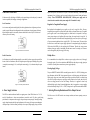
User’s Manual
For
M550
The content in this manual has been carefully prepared and is believed to be accurate, but no
responsibility is assumed for inaccuracies.
Rayne Motors reserves the right to make changes without further notice to any products herein to
improve reliability, function or design. Rayne Motors does not assume any liability arising out of the
application or use of any product or circuit described herein; neither does it convey any license
under its patent rights of others.
High Performance Microstepping Drive
Version 1.0
©2009 All Rights Reserved
Attention: Please read this manual carefully before using the Drive!
Rayne Motors general policy does not recommend the use of its products in life support or aircraft
applications wherein a failure or malfunction of the product may directly threaten life or injury.
According to Rayne Motors terms and conditions of sales, the user of Rayne Motors products in life
support or aircraft applications assumes all risks of such use and indemnifies Rayne Motors against all
damages.
Contents
Table of Contents
1. Introduction, Features and Applications.................................................................... 1
Introduction ........................................................................................................... 1
Features ................................................................................................................. 1
Applications .......................................................................................................... 1
2. Specifications ............................................................................................................ 1
Electrical Specifications ........................................................................................ 1
Operating Environment and other Specifications.................................................. 2
Mechanical Specifications..................................................................................... 2
Elimination of Heat ............................................................................................... 2
3. Pin Assignment and Description ............................................................................... 3
Connector P1 Configurations ................................................................................ 3
Selecting Active Pulse Edge or Active Level and Control Signal Mode............... 4
Connector P2 Configurations ................................................................................ 4
4. Control Signal Connector (P1) Interface................................................................... 5
5. Connecting the Motor................................................................................................ 5
Connections to 4-lead Motors ............................................................................... 5
Connections to 6-lead Motors ............................................................................... 6
Half Coil Configurations ............................................................................... 6
Full Coil Configurations................................................................................ 6
Connections to 8-lead Motors ............................................................................... 7
Series Connections ........................................................................................ 7
Parallel Connections...................................................................................... 7
6. Power Supply Selection ............................................................................................ 7
Regulated or Unregulated Power Supply .............................................................. 8
Multiple Drives ..................................................................................................... 8
Selecting Supply Voltage....................................................................................... 8
7. Selecting Microstep Resolution and Drive Output Current....................................... 8
Microstep Resolution Selection ............................................................................ 9
Current Settings..................................................................................................... 9
I
Contents
Dynamic current setting .............................................................................. 10
Standstill current setting.............................................................................. 10
8. Wiring Notes ........................................................................................................... 10
9. Typical Connection.................................................................................................. 11
10. Sequence Chart of Control Signals ....................................................................... 11
11. Protection Functions.............................................................................................. 12
Short-voltage and Over-voltage protection ......................................................... 12
Over-current Protection....................................................................................... 12
Short Circuit Protection....................................................................................... 12
12. Frequently Asked Questions.................................................................................. 12
Problem Symptoms and Possible Causes ............................................................ 13
APPENDIX ................................................................................................................. 14
Twelve Month Limited Warranty ........................................................................ 14
Exclusions ........................................................................................................... 14
Obtaining Warranty Service ................................................................................ 14
Warranty Limitations........................................................................................... 14
Contact Us................................................................................................................... 15
II
M550 Microstepping Driver Manual V1.0
M550 Microstepping Driver Manual V1.0
Operating Environment and other Specifications
1. Introduction, Features and Applications
Cooling
Introduction
The M550 is a high performance microstepping Drive based on pure-sinusoidal current control
technology. Owing to the above technology and the self-adjustment technology (self-adjust current
control parameters) according to different motors, the driven motors can run with smaller noise,
lower heating, smoother movement and have better performances at higher speed than most of the
Drives in the markets. It is suitable for driving 2-phase and 4-phase hybrid stepping motors.
Operating Environment
Features
l High performance, cost-effective
l Supply voltage up to +45 VDC
l Output current up to 5.0A
l Self-adjustment technology
l Pure-sinusoidal current control technology
l Pulse input frequency up to 300 KHz
l TTL compatible and optically isolated input
l Automatic idle-current reduction
l 16 selectable resolutions in decimal and
binary, up to 51,200 steps/rev
l Suitable for 2-phase and 4-phase motors
l Support PUL/DIR and CW/CCW modes
l Short-voltage, over-voltage, over-current
protections
Natural Cooling or Forced cooling
Avoid dust, oil fog and corrosive gases
Environment
Ambient Temperature
0℃ - 40℃ (32℉ - 104℉)
Humidity
40%RH - 90%RH
Operating Temperature
70℃ (158℉) Max
Vibration
5.9m/s2 Max
Storage Temperature
-20℃ - 65℃ (-4℉ - 149℉)
Weight
Approx. 280g (10 oz)
Mechanical Specifications (unit: mm [inch])
Applications
Suitable for a wide range of stepping motors, from NEMA size 17 to 34. It can be used in various
kinds of machines, such as X-Y tables, engraving machines, labeling machines, laser cutters,
pick-place devices, and so on. Particularly adapt to the applications desired with low noise, low
heating, high speed and high precision.
2. Specifications
Electrical Specifications (Tj = 25℃/77℉)
Parameters
M550
Min
Typical
Max
Unit
Output current
1.0
-
5.0 (3.57 RMS)
A
Supply voltage
+20
+36
+45
VDC
Logic signal current
7
10
16
mA
Pulse input frequency
0
-
300
kHz
Isolation resistance
500
MΩ
Figure 1: Mechanical specifications
*Recommend use side mounting for better heat dissipation
Elimination of Heat
l
Drive’s reliable working temperature should be <70℃(158℉), and motor working temperature
should be <80℃(176℉);
M550 Microstepping Driver Manual V1.0
l
l
It is recommended to use automatic idle-current mode, namely current automatically reduce to
60% when motor stops, so as to reduce Drive heating and motor heating;
The Drive must be mounted vertically to maximize heat sink area as shown in the following
picture. Use forced cooling method to cool the system if necessary.
M550 Microstepping Driver Manual V1.0
DIR+
DIRENA+
ENA-
DIR signal: In single-pulse mode, this signal has low/high voltage levels,
representing two directions of motor rotation; in double-pulse mode (set by
inside jumper J3), this signal is counter-clock (CCW) pulse,active at high
level or low level (set by inside jumper J1, J2). For reliable motion response,
DIR signal should be ahead of PUL signal by 5μs at least. 4-5V when
DIR-HIGH, 0-0.5V when DIR-LOW. Please note that rotation direction is also
related to motor-Drive wiring match. Exchanging the connection of two wires
for a coil to the Drive will reverse motion direction.
Enable signal: This signal is used for enabling/disabling the Drive. High level
(NPN control signal, PNP and Differential control signals are on the contrary,
namely Low level for enabling.) for enabling the Drive and low level for
disabling the Drive. Usually left UNCONNECTED (ENABLED).
Selecting Active Pulse Edge or Active Level and Control Signal Mode
There are three jumpers J1, J2 and J3 inside the M550 specifically for selecting active pulse edge or
effective level and control signal mode, as shown in figure 2. Default setting is PUL/DIR mode and
rising edge active (NPN, and PNP control signal is on the contrary).
Important NOTE: The driver must be mounted vertically onto
a plate or a heat sinking to maximize heat sink area as shown
in the above picture. Please use additional heat sinking or cool
fan if necessary.
(a) J1, J2, J3 open circuit
PUL/DIR mode and Active at rising edge (NPN)
3. Pin Assignment and Description
(c) J2, J3 open circuit, J1 shirt circuit
(d) J1, J2, J3short circuit
CW/CCW mode and active
CW/CCW mode and active
at low level (The fixed level)
at high level (The fixed level)
Figure 2: J1, J2 and J3 jumpers
The M550 has two connectors, connector P1 for control signals connections, and connector P2 for
power and motor connections. The following tables are brief descriptions of the two connectors.
More detailed descriptions of the pins and related issues are presented in section 4, 5, 9.
Connector P1 Configurations
Pin Function
PUL+
PUL-
Details
Pulse signal: In single pulse (pulse/direction) mode, this input represents pulse
signal, each rising or falling edge active (set by inside jumper J1); 4-5V when
PUL-HIGH, 0-0.5V when PUL-LOW. In double pulse mode (pulse/pulse) ,
this input represents clockwise (CW) pulse,active at high level or low level
(set by inside jumper J1, J2). For reliable response, pulse width should be
longer than 1.5μs. Series connect resistors for current-limiting when +12V or
+24V used. The same as DIR and ENA signals.
(b) J1, J2 open circuit, J3 short circuit
PUL/DIR mode and active at falling edge (NPN)
Connector P2 Configurations
Pin Function
+V
Details
Power supply, 20~45 VDC, Including voltage fluctuation and EMF voltage.
GND
Power Ground.
A+, A-
Motor Phase A
B+, B-
Motor Phase B
M550 Microstepping Driver Manual V1.0
4. Control Signal Connector (P1) Interface
The M550 can accept differential and single-ended inputs (including open-collector and PNP output).
The M550 has 3 optically isolated logic inputs which are located on connector P1 to accept line Drive
control signals. These inputs are isolated to minimize or eliminate electrical noises coupled onto the
drive control signals. Recommend use line Drive control signals to increase noise immunity of the
Drive in interference environments. In the following figures, connections to open-collector and PNP
signals are illustrated.
M550 Microstepping Driver Manual V1.0
determine the peak output current.
Figure 5: 4-lead Motor Connections
Connections to 6-lead Motors
Like 8 lead stepping motors, 6 lead motors have two configurations available for high speed or high
torque operation. The higher speed configuration, or half coil, is so described because it uses one half
of the motor’s inductor windings. The higher torque configuration, or full coil, uses the full windings
of the phases.
Half Coil Configurations
Figure 3: Connections to open-collector signal (common-anode)
As previously stated, the half coil configuration uses 50% of the motor phase windings. This gives
lower inductance, hence, lower torque output. Like the parallel connection of 8 lead motor, the torque
output will be more stable at higher speeds. This configuration is also referred to as half chopper. In
setting the Drive output current multiply the specified per phase (or unipolar) current rating by 1.4 to
determine the peak output current.
Figure 6: 6-lead motor half coil (higher speed) connections
Full Coil Configurations
Figure 4: Connection to PNP signal (common-cathode)
5. Connecting the Motor
The full coil configuration on a six lead motor should be used in applications where higher torque at
lower speeds is desired. This configuration is also referred to as full copper. In full coil mode, the
motors should be run at only 70% of their rated current to prevent over heating.
The M550 can drive any 2-pahse and 4-pahse hybrid stepping motors.
Connections to 4-lead Motors
4 lead motors are the least flexible but easiest to wire. Speed and torque will depend on winding
inductance. In setting the Drive output current, multiply the specified phase current by 1.4 to
Figure 7: 6-lead motor full coil (higher torque) connections
M550 Microstepping Driver Manual V1.0
Connections to 8-lead Motors
8 lead motors offer a high degree of flexibility to the system designer in that they may be connected
in series or parallel, thus satisfying a wide range of applications.
Series Connections
M550 Microstepping Driver Manual V1.0
higher motor speed to be achieved, at the price of more noise and heating. If the motion speed
requirement is low, it’s better to use lower supply voltage to decrease noise, heating and improve
reliability. Note: MEANWELL DRP-240-24(24VDC, 240Watt power supply) must be
selected in order to make the whole system comply with UL standards for safety.
Regulated or Unregulated Power Supply
A series motor configuration would typically be used in applications where a higher torque at lower
speeds is required. Because this configuration has the most inductance, the performance will start to
degrade at higher speeds. In series mode, the motors should also be run at only 70% of their rated
current to prevent over heating.
Figure 8: 8-lead motor series connections
Both regulated and unregulated power supplies can be used to supply the Drive. However,
unregulated power supplies are preferred due to their ability to withstand current surge. If regulated
power supplies (such as most switching supplies.) are indeed used, it is important to have large
current output rating to avoid problems like current clamp, for example using 4A supply for 3A
motor-Drive operation. On the other hand, if unregulated supply is used, one may use a power supply
of lower current rating than that of motor (typically 50%~70% of motor current). The reason is that
the Drive draws current from the power supply capacitor of the unregulated supply only during the
ON duration of the PWM cycle, but not during the OFF duration. Therefore, the average current
withdrawn from power supply is considerably less than motor current. For example, two 3A motors
can be well supplied by one power supply of 4A rating.
Parallel Connections
Multiple Drives
An 8 lead motor in a parallel configuration offers a more stable, but lower torque at lower speeds. But
because of the lower inductance, there will be higher torque at higher speeds. Multiply the per phase
(or unipolar) current rating by 1.96, or the bipolar current rating by 1.4, to determine the peak output
current.
It is recommended to have multiple Drives to share one power supply to reduce cost, if the supply
has enough capacity. To avoid cross interference, DO NOT daisy-chain the power supply input pins
of the Drives. (Instead, please connect them to power supply separately.)
Figure 9: 8-lead motor parallel connections
Selecting Supply Voltage
The power MOSFETS inside the M550 can actually operate within +20 ~ +50VDC, including power
input fluctuation and back EMF voltage generated by motor coils during motor shaft deceleration.
Higher supply voltage can increase motor torque at higher speeds, thus helpful for avoiding losing
steps. However, higher voltage may cause bigger motor vibration at lower speed, and it may also
cause over-voltage protection or even Drive damage. Therefore, it is suggested to choose only
sufficiently high supply voltage for intended applications, and it is suggested to use power supplies
with theoretical output voltage of +20 ~ +45VDC, leaving room for power fluctuation and back-EMF.
6. Power Supply Selection
7. Selecting Microstep Resolution and Drive Output Current
The M550 can match medium and small size stepping motors (from NEMA frame size 17 to 34)
made by Rayne Motors or other motor manufactures around the world. To achieve good driving
performances, it is important to select supply voltage and output current properly. Generally speaking,
supply voltage determines the high speed performance of the motor, while output current determines
the output torque of the driven motor (particularly at lower speed). Higher supply voltage will allow
This Drive uses an 8-bit DIP switch to set microstep resolution, and motor operating current, as
shown below:
M550 Microstepping Driver Manual V1.0
M550 Microstepping Driver Manual V1.0
the selection also depends on leads and connections.
The first three bits (SW1, 2, 3) of the DIP switch are used to set the dynamic current. Select a setting
closest to your motor’s required current.
Dynamic current setting
Microstep Resolution Selection
Microstep resolution is set by SW5, 6, 7, 8 of the DIP switch as shown in the following table:
Microstep
Steps/rev.(for 1.8°motor)
SW5
SW6
SW7
SW8
2
400
ON
ON
ON
ON
4
800
OFF
ON
ON
ON
8
1600
ON
OFF
ON
ON
16
3200
OFF
OFF
ON
ON
32
6400
ON
ON
OFF
ON
64
12800
OFF
ON
OFF
ON
128
25600
ON
OFF
OFF
ON
256
51200
OFF
OFF
OFF
ON
5
1000
ON
ON
ON
OFF
10
2000
OFF
ON
ON
OFF
20
4000
ON
OFF
ON
OFF
25
5000
OFF
OFF
ON
OFF
40
8000
ON
ON
OFF
OFF
50
10000
OFF
ON
OFF
OFF
100
20000
ON
OFF
OFF
OFF
200
40000
OFF
OFF
OFF
OFF
Current Settings
For a given motor, higher Drive current will make the motor to output more torque, but at the same
time causes more heating in the motor and Drive. Therefore, output current is generally set to be such
that the motor will not overheat for long time operation. Since parallel and serial connections of
motor coils will significantly change resulting inductance and resistance, it is therefore important to
set Drive output current depending on motor phase current, motor leads and connection methods.
Phase current rating supplied by motor manufacturer is important in selecting Drive current, however
Peak Current
1.21A
RMS Current
0.87A
SW1
ON
SW2
ON
SW3
ON
1.73A
2.27A
2.81A
3.37A
1.24A
1.62A
2.01A
2.41A
OFF
ON
OFF
ON
ON
OFF
OFF
ON
ON
ON
ON
OFF
3.93A
4.46A
5.00A
2.81A
3.19A
3.57A
OFF
ON
OFF
ON
OFF
OFF
OFF
OFF
OFF
Notes: Due to motor inductance, the actual current in the coil may be smaller than the dynamic
current setting, particularly under high speed condition.
Standstill current setting
SW4 is used for this purpose. OFF meaning that the standstill current is set to be half of the selected
dynamic current, and ON meaning that standstill current is set to be the same as the selected dynamic
current.
The current automatically reduced to 60% of the selected dynamic current one second after the last
pulse. Theoretically, this will reduce motor heating to 36% (due to P=I2*R) of the original value. If
the application needs a different standstill current, please contact Rayne Motors.
8. Wiring Notes
l
In order to improve anti-interference performance of the Drive, it is recommended to use
twisted pair shield cable.
l
To prevent noise incurred in PUL/DIR signal, pulse/direction signal wires and motor wires
should not be tied up together. It is better to separate them by at least 10 cm, otherwise the
disturbing signals generated by motor will easily disturb pulse direction signals, causing motor
position error, system instability and other failures.
l
If a power supply serves several Drives, separately connecting the Drives is recommended
instead of daisy-chaining.
M550 Microstepping Driver Manual V1.0
l
It is prohibited to pull and plug connector P2 while the Drive is powered ON, because there is
high current flowing through motor coils (even when motor is at standstill). Pulling or plugging
connector P2 with power on will cause extremely high back-EMF voltage surge, which may
damage the Drive.
9. Typical Connection
A complete stepping system should include stepping motor, stepping Drive, power supply and
controller (pulse generator). A typical connection is shown as figure 10.
M550 Microstepping Driver Manual V1.0
Remark:
a)
t1: ENA must be ahead of DIR by at least 5µs. Usually, ENA+ and ENA- are NC (not
connected). See “Connector P1 Configurations” for more information.
b)
t2: DIR must be ahead of PUL effective edge by 5µs to ensure correct direction;
c)
t3: Pulse width not less than 1.5µs;
d)
t4: Low level width not less than 1.5µs.
11. Protection Functions
To improve reliability, the Drive incorporates some built-in protections features.
Short-voltage and Over-voltage protection
When power supply voltage is lower than +16VDC, short-voltage protection will be activated and the
power indicator LED will turn off. When the power supply voltage is back to normal operation range,
the Drive will automatically reset and power indicator LED will turn on.
When power supply voltage exceeds +52VDC, over-voltage protection will be activated and power
indicator LED will turn red.
Figure 10: Typical connection
Over-current Protection
10. Sequence Chart of Control Signals
Protection will be activated when continuous current reaches to 16A.
In order to avoid some fault operations and deviations, PUL, DIR and ENA should abide by some
rules, shown as following diagram:
Short Circuit Protection
Protection will be activated in case of short circuit between motor coils or between motor coil and
ground.
When above protections are active, the motor shaft will be free or the LED will turn red (except
short-voltage protection). Reset the Drive by repowering it to make it function properly after
removing above problems.
12. Frequently Asked Questions
Figure 11: Sequence chart of control signals
In the event that your Drive doesn’t operate properly, the first step is to identify whether the problem
is electrical or mechanical in nature. The next step is to isolate the system component that is causing
the problem. As part of this process you may have to disconnect the individual components that make
up your system and verify that they operate independently. It is important to document each step in
the troubleshooting process. You may need this documentation to refer back to at a later date, and
M550 Microstepping Driver Manual V1.0
M550 Microstepping Driver Manual V1.0
these details will greatly assist our Technical Support staff in determining the problem should you
need assistance.
APPENDIX
Many of the problems that affect motion control systems can be traced to electrical noise, controller
software errors, or mistake in wiring.
Twelve Month Limited Warranty
Problem Symptoms and Possible Causes
Symptoms
Possible Problems
No power
Microstep resolution setting is wrong
Motor is not rotating
DIP switch current setting is wrong
Fault condition exists
The Drive is disabled
Motor rotates in the wrong direction
The Drive in fault
Motor phases may be connected in reverse
DIP switch current setting is wrong
Something wrong with motor coil
Control signal is too weak
Control signal is interfered
Erratic motor motion
Wrong motor connection
Something wrong with motor coil
Current setting is too small, losing steps
Current setting is too small
Motor stalls during acceleration
Motor is undersized for the application
Acceleration is set too high
Power supply voltage too low
Excessive motor and Drive heating
Rayne Motors warrants its products against defects in materials and
workmanship for a period of 12 months from shipment out of factory. During the warranty period,
Rayne Motors will either, at its option, repair or replace products which proved to be defective.
Exclusions
The above warranty does not extend to any product damaged by reasons of improper or inadequate
handlings by customer, improper or inadequate customer wirings, unauthorized modification or
misuse, or operation beyond the electrical specifications of the product and/or operation beyond
environmental specifications for the product.
Obtaining Warranty Service
To obtain warranty service, a returned material authorization number (RMA) must be obtained
from customer service before returning product for service.
Customer shall prepay shipping charges for products returned to Rayne Motors for warranty service,
and Rayne Motors shall pay for return of products to customer.
Warranty Limitations
Rayne Motors makes no other warranty, either expressed or implied, with respect to the product.
Rayne Motors specifically disclaims the implied warranties of merchantability and fitness for a
particular purpose. Some jurisdictions do not allow limitations on how long and implied warranty
lasts, so the above limitation or exclusion may not apply to you. However, any implied warranty of
merchantability or fitness is limited to the 12-month duration of this written warranty.
Shipping Failed Product
If your product fail during the warranty period, e-mail customer service to
Inadequate heat sinking / cooling
obtain a returned material authorization number (RMA) before returning product for service.
Automatic current reduction function not being utilized
Please include a written description of the problem along with contact name and address. Send
Current is set too high
failed product to Rayne Motors
Also enclose information regarding the circumstances prior to product failure.
M550 Microstepping Driver Manual V1.0
.