1
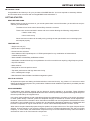
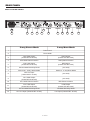
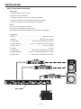
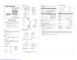
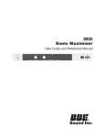
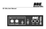
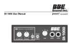
2 WAY STEREO
3 WAY MONO CROSSOVER
OWNERS MANUAL
�
SAFETY RELATED SYMBOLS
protective grounding wire or disconnect the wiring of
protective grounding terminal.
� � � � �� �
�� �� �� � �� �� �� �� ��� �� �
�� ��� � �� ��
• Operating Conditions
The symbol is used to indicate that some
hazardous live terminals are involved within
this apparatus, even under the normal
operating conditions.
The symbol is used in the service
documentation to indicate that a specific
component shall be only replaced by the
component specified in that documentation
for safety reasons.
This apparatus shall not be exposed to dripping or
splashing and that no objects filled with liquids, such
as vases, shall be placed on this apparatus.
To reduce the risk of fire or electric shock, do not
expose this apparatus to rain or moisture.
Do not use this apparatus near water. Install in
accordance with the manufacturer’s instructions.
Protective grounding terminal.
Do not install near any heat sources such as radiators,
heat registers, stoves, or other apparatus (including
amplifiers) that produce heat.
Alternating current /voltage.
Do not block any ventilation openings.
Hazardous live terminal.
No naked flame sources, such as lighted candles,
should be placed on the apparatus.
ON: Denotes the apparatus is turned on.
OFF: Denotes the apparatus is turned off, because
it uses the single pole switch, be sure to unplug the
AC power to prevent any electric shock before you
proceed with your service.
WARNING: Describes precautions that should be
observed to prevent the danger of injury or death to
the user.
CAUTION: Describes precautions that should be
observed to prevent danger of the apparatus.
WARNING
• Power Supply
Ensures the source voltage matches the voltage of
the power supply before turning ON the apparatus.
Unplug this apparatus during lightning storms or when
unused for long periods of time.
• External Connection
The external wiring connected to the output hazardous
live terminals requires installation by an instructed
person, or the use of ready-made leads or cords.
• Do not Remove any Cover
There are maybe some areas with high voltages
inside, to reduce the risk of electric shock, do not
remove any cover if the power supply is connected.
The cover should be removed by qualified personnel
only.
No user serviceable parts inside.
IMPORTANT SAFETY INSTRUCTIONS
• Read these instructions.
• Heed all warnings.
• Follow all instructions.
• Keep these instructions.
Only use attachments/accessories specified by the
manufacturer.
• Power Cord and Plug
Do not defeat the safety purpose of the polarized or
grounding type plug. A polarized plug has two blades
with one wider than the other. A grounding type plug
has two blades and a third grounding prong. The
wide blade or the third prong are provided for your
safety. If the provided plug does not fit into your outlet,
consult an electrician for replacement of the obsolete
outlet. Protect the power cord from being walked
on or pinched particularly at the plug, convenience
receptacles, and the point where they exit from the
apparatus.
• Cleaning
When the apparatus needs a cleaning, you can blow
off dust from the apparatus with a blower or clean
with a rag etc. Don’t use solvents such as benzol,
alcohol, or other fluids with very strong volatility
and flammability for cleaning the apparatus body.
Clean only with a dry cloth.
• Servicing
• Fuse
To prevent a fire, make sure to use fuses with specified
standard (current, voltage, type). Do not use a different
fuse or short circuit the fuse holder.
Before replacing the fuse, turn OFF the apparatus
and disconnect the power source.
• Protective Grounding
Make sure to connect the protective grounding to
prevent any electric shock before turning ON the
apparatus. Never cut off the internal or external
— i —
Refer all servicing to qualified personnel. To reduce
the risk of electric shock, do not perform any servicing
other than that contained in the operating instructions
unless you are qualified to do so.
Servicing is required when the apparatus has been
damaged in any way, such as the power supply cord
or plug is damaged, liquid has been spilled or objects
have fallen into the apparatus, the apparatus has
been exposed to rain or moisture, does not operate
normally, or has been dropped.
CONTENTS
SPECIFICATIONS ……………………………………………………………………………………… III
SERVICE ………………………………………………………………………………………………… III
WARRANTY ……………………………………………………………………………………………… III
INTRODUCTION ………………………………………………………………………………………… 1
GETTING STARTED …………………………………………………………………………………… 1
READ BEFORE USING ………………………………………………………………………… 1
FEATURE LIST…………………………………………………………………………………… 1
INPUTS & OUTPUTS …………………………………………………………………………… 1
SONIC MAXIMIZER …………………………………………………………………………… 1
CLIP LED ………………………………………………………………………………………… 2
RANGE X1 & X10 ……………………………………………………………………………… 2
PHASE INVERSION …………………………………………………………………………… 2
MODE SWITCH ………………………………………………………………………………… 2
MAX-X3
-X3 FRONT PANEL ………………………………………………………………………………… 3
MAX-X3
-X3 REAR PANEL ………………………………………………………………………………… 4
MAX-X3 CONNECTION EXAMPLES ………………………………………………………………… 5
MAX-X3 2-WAY STEREO OPERATION ……………………………………………………… 5
MAX-X3 3-WAY MONO OPERATION ………………………………………………………… 6
CONNECTION CABLES ………………………………………………………………………………… 7
— ii —
SPECIFICATIONS
SPECIFICATIONS
CROSSOVER TYPE ……………………………………………………………………… Mono 3 way/Stereo 2 way
FILTER TYPE ……………………………………………………………………………… Linkwitz/Riley 24dB/octave
CROSSOVER FREQUENCY Max-X3
LOW-MID Range 1 ……………………………………………………………………………………… 80Hz-1KHz
MID-HIGH Range 10
INPUTS:
…………………………………………………………………………………800Hz-10KHz
TYPE ……………………………………………………………… Balanced XLR and Unbalanced 1/4”
IMPEDANCE …………………………………………………………………………………… 100KOhms
OUTPUTS: TYPE ……………………………………………………………… Balanced XLR and Unbalanced 1/4”
IMPEDANCE …………………………………………………………………………………… 600 Ohms
HUM & NOISE
…………………………………………………………………………………… AV=0dB, fc=800Hz
LOW SECTION (OUTPUT@0dB)
…………………………………………………………………………… -106dBu
HIGH SECTION (OUTPUT@0dB) ………………………………………………………………………………-97dBu
S/N RATIO
………………………………………………………………………………………………………… 118dB
POWER SUPPLY
………………………………………………………………………… see label on the apparatus
DIMENSIONS ……………………………………… 483mm(W) 194.5(D) 44mm(H) /19.01”(W) 7.66”(D) 1.73”(H)
WEIGHT
……………………………………………………………………………………………………2.5Kg (5.51lb)
SERVICE
We recommend that if at all possible, a BBE Max-X3 which requires service be sent to our facility in Huntington Beach, California. We request that a “RETURN AUTHORIZATION” be issued by the dealer from whom you purchased the unit. If this is not
possible, call BBE Sound, Inc. directly at (714) 897-6766, extension 116 to obtain a “RETURN AUTHORIZATION”. Include a
copy of the bill of sale with the unit when it is shipped to BBE Sound, Inc. so that the service can be expedited.
As the repair turnaround time is minimal, we request that the unit be sent to BBE Sound, Inc. We also need to add reliability
data to our files so that future revisions may be undertaken, if necessary, to improve the product. If unit has been purchased
outside the US, please contact your national distributor.
WARRANTY
Warranty registration of the unit to BBE Sound, Inc. is not necessary. It is strongly recommended that you retain a copy of the
bill of sale for future reference.
IT IS THE SOLE RESPONSIBILITY OF THE END USER TO PROVIDE THE BILL OF SALE OR OTHER MEANS OF PROOF
OF PURCHASE TO VALIDATE THE WARRANTY IF WARRANTY SERVICE IS REQUESTED.
The BBE Max-X3 is warranted against defects in material and workmanship for a period of two (2) years from date of purchase from
BBE Sound Inc. or from an authorized dealer. During this period, we will repair units free of charge providing that they are shipped
prepaid to BBE Sound, Inc., 5381 Production Drive, Huntington Beach, CA 92649. We will pay return UPS shipping charges within
the USA. All charges related to non-UPS shipping, including customs clearance, will be billed. The warranty will be honored for the
longer of either 90 days from the date of any service or the remainder of the original 2 year factory warranty.
This warranty will be considered null and void by BBE Sound, Inc. if any of the following is found:
1. The equipment has been physically damaged.
2. The equipment shows signs of abuse.
3. The equipment has been electrically damaged by improper connection or attempted repair by the customer or a third party.
4. The equipment has been modified without authorization.
5. The bill of sale indicates that the purchase date of the equipment is not within the warranty period.
All non-warranty repairs are warranted for a period of 90 days from the date of service.
BBE Sound, Inc. is NOT LIABLE FOR CONSEQUENTIAL DAMAGES. Should the unit fail to operate for any reason, our sole
obligation is to repair it as described above.
DO NOT RETURN ANY PRODUCT TO THE ABOVE ADDRESS WITHOUT INSTRUCTIONS AND AUTHORIZATION ISSUED BY THE ABOVE LOCATION.
— iii —
GETTING STARTED
INTRODUCTION
Congratulations and thank you for your purchase of the BBE Max-X3. You have acquired an extremely efficient
and universal stereo crossover with an integral BBE® Sonic Maximizer™.
GETTING STARTED
READ BEFORE USING
Before starting to use the crossover in your sound system there is some information you should know and procedures you should follow.
The Max-X3 is a fourth order Linkwitz-Riley electronic crossover.
These units can be used both in stereo and mono modes allowing the following configurations:
• Stereo mode 2-way
• Mono mode 3-way
Stereo and mono modes can be easily set by pushing the rear panel switch and connecting inputs
and outputs properly.
FEATURE LIST
• Single rack unit (1U)
• Robust and compact design
• Phase inversion switches
• Servo-balanced XLR inputs/outputs. 1/4”TRS input/outputs for any combination of balanced and
unbalanced operation
• State-variable Linkwitz/Riley 24dB/Octave filters
• Switchable Constant Directivity horn equalization circuit for use with horns requiring a high frequency boost
• Clip LED indicators
• Mute switches
• Designed for the most precise control
• Top audio performance with high slew rate circuity
• Over 115dB dynamic range
• Manufactured Under ISO9001 Certified management system
INPUTS & OUTPUTS
All inputs and outputs are floating and balanced when connected via a tip, ring, sleeve 1/4” connector to other
floating and balanced equipment. Any combination of balanced and unbalanced operation is permitted (see also
“Connection Cables”).
SONIC MAXIMIZER
Loudspeakers have difficulty working with the electronic signals supplied by an amplifier. These difficulties
cause such major phase and amplitude distortion that the sound reproduced by speaker differs significantly from
the sound produced by the original source.
In the past, these problems proved unsolvable and were thus delegated to a position of secondary importance
in audio system design. However, phase and amplitude integrity is essential to accurate sound reproduction.
Research shows that the information which the listener translates into the recognizable characteristics of a live
performance are intimately tied into complex time and amplitude relationships between the fundamental and
harmonic components of a given musical note or sound. These relationships define a sound’s “sound”.
When these complex relationships pass through a speaker, the proper order is lost. The higher frequencies are
delayed. A lower frequency may reach the listener’s ear first or perhaps simultaneously with that of a higher
frequency. In some cases, the fundamental components may be so time-shifted that they reach the listener’s
ear ahead of some or all of the harmonic components.
— 1 —
INTRODUCTION
This change in the phase and amplitude relationship on the harmonic and fundamental frequencies is technically called “envelope distortion.” The listener perceives this loss of sound integrity in the reproduced sound as
“muddy” and “smeared.” In the extreme, it can become difficult to tell the difference between musical instruments, for example, an oboe and a clarinet.
BBE Sound, Inc. conducted extensive studies of numerous speaker systems over a ten year period. With this
knowledge, it became possible to identify the characteristics of an ideal speaker and to distill the corrections
necessary to return the fundamental and harmonic frequency structures to their correct order. While there are
differences among various speaker designs in the magnitude of their correction, the overall pattern of correction
needed is remarkably consistent.
The BBE Process is so unique that 42 patents have been awarded by the U.S. Patent Office.
CLIP LED
This LED will light when output capability is being exceeded with clipping distortion. Occasional flickering of the
Clip LED is acceptable, but if it remains on continuously you should turn down the level control or reduce the
output level of the preceding component to avoid audible distortion.
RANGE X1 & X10
This switch sets the range of crossover frequencies.
OFF : Frequency x1 = 80Hz -1KHz
ON : Frequency x10 = 800Hz -10KHz
CAUTION: to prevent transients and possible equipment damage, never
change the frequency range switch from the x1 position to the x 10 (or vice
versa) while passing signal.
PHASE INVERSION
These phase inversion switches reverse the audio signal’s phase by 180˚ . Normally, you won’t need this switch,
however, in some cases, it might be necessary. For example, the inversion of the pins of the XLR connector may
be necessary to alter the audio phase to compensate for phase cancellation.
MODE SWITCH
This switch sets the operational mode of this unit. When it is pressed, this unit is in the state of mono application, you can operate it as a 3-way mono crossover (High/Mid/Low). Otherwise, this unit is in the state of stereo
application, you can operate it as a 2-way stereo crossover (High/Low).
— 2 —
FRONT PANEL
Max-X3 FRONT PANEL
1
12
2
4
3
6
5
8
7
10
9
13
11
15
14
17
16
19
18
21
20
22
23
2-way Stereo Mode
3-way Mono Mode
1
Ch1 BBE Process Control
BBE Process Control
2
Ch1 BBE Lo Contour Control
BBE Lo Contour Control
3
Ch1 BBE switch
BBE switch
4
Ch1 Input Level
Input Level
5
Ch1 LOW & Ch1 HIGH Clip LEDs
Low & Mid Clip LEDs
6
Ch1 LOW Gain
LOW Gain
7
Ch1 LOW Mute
LOW Mute
8
Ch1 LOW-HIGH Crossover Frequency
LOW-MID Crossover Frequency
9
Ch1 LOW-HIGH Crossover Range
LOW-MID Crossover Range
10
Ch1 HIGH Gain
(not used)
11
Ch1 HIGH Mute
(not used)
12
Ch2 BBE Process Control
(not used)
13
Ch2 BBE Lo Contour Control
(not used)
14
Ch2 BBE switch
(not used)
15
Ch2 Input Level
(not used)
16
Ch2 LOW & Ch1 HIGH Clip LEDs
HIGH Clip LED
17
Ch2 LOW Gain
MID Gain
18
Ch2 LOW Mute
MID Mute
19
Ch2 LOW-HIGH Crossover Frequency
MID-HIGH Crossover Frequency
20
Ch2 LOW-HIGH Crossover Range
MID-HIGH Crossover Range
21
Ch2 HIGH Gain
HIGH Gain
22
Ch2 HIGH Mute
HIGH Mute
23
POWER SWITCH
— 3 —
REAR PANEL
Max-X3 REAR PANEL
2W-STEREO
HIGH OUT 2
LOW OUT 2
BALANCED
BALANCED
95-120V /210-240V 60-50Hz
Rated power consumption 10w
HIGH
PHASE
FUSE
210-240V T100mAL 250VAC
95-120V 200mA 250VAC
Replace fuse with correct
type only
MADE IN CHINA
C
STEREO MONO
BALANCED
HIGH OUT 1
BALANCED
UNBALANCED
CD
BOOST MODE
CHANNEL 1 IN
LOW OUT 1
BALANCED
UNBALANCED
BALANCED
UNBALANCED
HIGH
PHASE
UNBALANCED
CD
BOOST
US
3W-MONO
HIGH OUT MONO
MID OUT MONO
MONO INPUT
LOW OUT MONO
1
2
CHANNEL 2 IN
UNBALANCED
UNBALANCED
AC INPUT
7
3
4
5
6
8
2-way Stereo Mode
9
10
11
12
3-way Mono Mode
1
Power Cord
2
Fuse Holder
3
Ch2 HIGH Output
(Linked XLR-M & Jack)
HIGH Output
(Linked XLR-M & Jack)
4
Ch2 HIGH Phase Inversion
HIGH phase inversion
5
Ch2 LOW Output
(Linked XLR-M & Jack)
MID Output
(Linked XLR-M & Jack)
6
Ch2 Constant Directivity Boost
(not used)
7
Switch Out - 2-way Stereo Mode
Switch In - 3-way Mono Mode
8
Ch2 Line Input
(Linked XLR-F & Jack)
(not used)
9
Ch1 HIGH Output
(Linked XLR-M & Jack)
(not used)
10
Ch1 HIGH Phase Inversion
MID Phase Inversion
11
Ch1 LOW Output
(Linked XLR-M & Jack)
LOW Output
(Linked XLR-M & Jack)
12
Ch1 Constant Directivity Boost
Constant Directivity Boost
13
Ch1 Line Input (Linked XLR-F & Jack)
Line Input (Linked XLR-F & Jack)
— 4 —
13
INSTALLATION
Max-X3 CONNECTION EXAMPLES
Max-X3 2-WAY STEREO OPERATION
1. Set Mode switch to stereo Mode.
2. Plug the Left line-in to INPUT 1 and the Right line-in to INPUT 2.
3. Connect the LOW OUT 1 to the Left input of the Low frequency amplifier,
and the LOW OUT 2 to the Right input of Low frequency amplifier.
4. Connect the HIGH OUT 1 to the Left input of the High frequency amplifier,
and the HIGH OUT 2 to the Right input of High frequency amplifier.
5. Set the XOVER FREQ 1 and XOVER FREQ 2.
— 5 —
INSTALLATION
MAX-X3 3-WAY MONO OPERATION
Rear Panel
1. Set Mode switch to Mono mode.
2. Plug the line-in into INPUT 1.
3. Connect LOW OUT 1 to the Low frequency amplifier.
4. Connect LOW OUT 2 to the Midrange frequency amplifier.
5. Connect HIGH OUT 2 to the High frequency amplifier.
NOTE:
Do not connect anything into INPUT 2.
Do not connect anything from HIGH OUT 1.
(The inputs/outputs are automatically normalled when unplugged).
Front Panel
1. BBE 1 …………………………………………………… BBE main control
2. INPUT 1 ………………………………………… main input level control
3. LOW GAIN 1 …………………… Low frequency amplifier level control
4. XOVER FREQ 1 …………… set to x1 - LOW-MID Crossover control
5. HIGH GAIN 1 …………………………………………… set to 0 and Mute
6. INPUT 2 …………………………………………………………… set to 0
7. LOW Gain 2 …………………… Mid frequency amplifier level control
8. XOVER FREQ 2 ………… set to x10 - MID-HIGH Crossover control
9. HIGH GAIN
…………………… High frequency amplifier level control
— 6 —
INSTALLATION
CONNECTION CABLES
In this chapter you’ll find the wiring diagrams for the connectors to be used with your crossover. Take care of
the connector cable. Always holding them by the connectors and avoiding knots and twists when coiling them:
this gives the advantage of increasing their life and reliability, which is always to your advantage . Periodically
check that your cables are in good condition, that they are correctly wired and that all their contact are perfectly
efficient: a great number of problems (faulty contacts, ground hum , discharges, etc.) are caused entirely by using unsuitable or faulty cables
XLR Male Jack unbalanced link
�
� � � � � � � �� � �
�
� �� � ��
� � ����
� ��
� �� ���
�
XLR Female Jack unbalanced link
�
�
� � � � � � � �� � �
� �� ���
� ��
� � ����
�
� �� � ��
Balanced XLR-M
�
� � ����
�
�
� � � � � ��
� � � ��� � �
Balanced XLR-F
�
� � � � � ��
�
�
� � ����
� � � ��� � �
Balanced 1/4” Plug
� �� � ��
� � ����
� ��
� ���
� � � ��� � �
— 7 —
� � � � � ��
�
5381 PRODUCTION DRIVE
HUNTINGTON BEACH, CA 92649
714-897-6766 • FAX 714-896-0736
WWW.BBESOUND.COM
COVERED BY U.S. PATENT 4,482,866 AND OTHER U.S. AND FOREIGN PATENTS PENDING.
BBE IS THE REGISTERED TRADEMARK OF BBE SOUND, INC.
REV 1: 3.11.2004