1
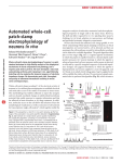
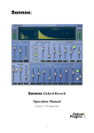
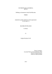
LINEAR AMPLIFIER 430 – 440 MHz BAND TELECOM 70CM HK User’s Manual INDEX PURPOSE…… ..........................................................…………………………..……………3 GENERAL INFORMATION 1:1. Introduction…… ......................................................................................................... .4 1:2. Physical Description………………………………………….. …….………………..4 1:3. Working Description…………………………………………………………… …….4 DESCRIPTION 2:1. Controls and indicators at the Front Panel… …………………………………………6 2:2. Connections at the Rear Panel………… ……………………………………………..8 INSTALLATION AND OPERATION 3:1. Amplifier 70CM HK installation……………… ..……………………………………9 3:2. Antenna’s requirements……………………… ...…………………………………….9 3:3. How to use the 70CM HK amplifier……………… ..………………………………...9 3:4. Cautions………………………………………………………………… …………..10 SPECIFICATIONS 4:1. Technical Specifications…………………… ……………………………………….12 4:2. Physical Specifications………………………………………………………………12 IMAGES/PICTURES LIST 1:1.Carryingbriefcase………………………… ..………………………………………….3 1:2.General Diagram of Connections…………… .………………………………………..4 1:3. Connection’s Control General Diagram with Transceiver……………………………5 1:4. Connection’s Control General Diagram with Sequencer… …………………………. 5 2:1. Amplifier’s Frontal View……………………………………………………………...6 2:2. Amplifier’s Front View Details……………………………………………………….7 2:3. Amplifier’s Rear View Details………………………………………………………..8 2 PURPOSE This manual contents important information about the installation and amplifier’s operation. This unit does not need any adjustment to be made by the users. The manual’s purpose is to familiarize the users with the possibilities of the amplifier, its connections and its features, as well. Image 1.1 Carrying briefcase 3 GENERAL INFORMATION 1 .1.INTRODUCTION Manual’s purpose This manual contents the physical and working descriptions of the linear amplifier for the two meter Radio Amateur Band, and the installation/operating instructions, as well. General Features The 70CM HK, is a top quality amplifier, with an RF power output of 500 W, specially designed to be used with transceivers, allowing to drive with an output power of 2.5 up to 5 Watt (Max.) on the 430 - 440MHz (Europe) / 420 - 440MHz (USA) Band. It provides a 23 dB gain. The last generation electronic circuitry provides all kind of protections, controlled by a microprocessor, protecting the amplifier against any kind of unwanted circumstances, such high SWR, overdrive, and so on. All the components used are of the top quality, like for example the coaxial relays from Tohtsu ®. 1.2 PHYSICAL DESCRIPTION The 70CM HK amplifier is a compact and transistorized linear amplifier, built in a metal housing to guarantee a perfect RF shielding. At its front part, are placed the functions indicators, which inform to the users, as the working circumstances and any protection’s performance, as the RF power output and SWR, by selecting it by the frontal knob. All the connections like power cord, antenna, transceiver and PTT control, are located at the rear part of the amplifier. 1.3 FUNCTION DESCRIPTION For a perfect equipment performance, all transceiver’s connections are shown on the following illustration: Diagram 1.2: Connections General Diagram. 4 It is highly recommended to connect the transceiver’s antenna output to the RF amplifier’s input, through a low loss jumping cable, with the correct length and by using the highest quality connectors. The cable from the antenna must be connected at the RF OUT coaxial connector. The antenna must be appropriated for the Band, in which the amplifier is working, in this case 430 – 440MHz (Europe) / 420 - 440MHz (USA); must present within this frequency range 50 Ohm impedance, and be suitable for a power r.m.s of 500W. The « Control » connector is used to place the amplifier at the « Transmission » position. The circuit must be closed (Grounded) when going to transmission. This procedure can be made by an external sequencer or through a signal coming from the transceiver. In that case, it will be necessary that there is a ground connection at the control exit, when pushing the PTT to transmit. Diagram 1.3: General Connections Diagram. Transceiver controller. Diagram 1.4: General Connections Diagram. Sequencer controller. The amplifier’s ventilation is made by cooling fans, with regulated speed, driven by the unit’s microprocessor. 5 DESCRIPTION 2.1 FRONT PANNEL CONTROLS & INDICATORS DESCRIPTION At the front panel of TELECOM 70CM HK, we have the following indicators and controls: 1. On-Off switch: Power ON when lighted. 2. On Air LED indicator: Green: Standby, RED: On air (TX) 3. Red LED temperature indicator: Lighted when protection switches the unit « OFF » due to high temperature. 4. Red LED SWR indicator: Lighted when protection switches the unit off due to high SWR. 6. RF Output and SWR meter. 7. Function meter selection knob. Image 2.1: Frontal View of 70CM-HK amplifier. 6 Image 2.2: Front View Details. (70CM-HK) 1. On-Off switch: Lighted in « ON » position. 2. State indicator LED: When Green lighted, indicates it is on standby position (by-pass), that is, in Reception mode. When the control signal is applied to the rear connector (no. 4), light changes to RED colour, indicating the « Transmission » (TX) state (ON AIR), and consequently, ready to amplify the RF signal coming from the transceiver. At start mode, when carrying the checking routine, this indicator makes three flashes together with the other three indicators at the same time. 3. Temperature indicator « Temp »: It warns about the excess of operating temperature. This indicator, yellow colour, starts flashing when the internal temperature exceeds the predetermined level but the amplifier continues operating normally. When the temperature is excessive, the yellow LED is continuously lighted and acting one of the protections, of which the amplifier is provided. It inhibits all functions, and does not allow the amplification. On the starting mode, the indicator makes the checking routine, by flashing three times together with the three indicators. 4. Power indicator « PWR »: Indicates that the maximum input power has been exceeded (4 W). When the programmed power input has been overdriven, the red LED indicator starts flashing. This flashing will continue, even if the power input level is decreased, until the unit will pass to the RX position or to « by- pass ». Also, on the starting mode, the LED will flash three times, with the three indicators. 5. SWR indicator: This red LED, advised about the excess of SWR, at least programmed on 1,7:1. When this level has been exceeded, the LED flashes to indicate it, and also activating another of the amplifier’s protections. Like the other cases, due to the checking routine, the indicator flashes three times, with the other three indicators. 7 6. RF Power Output and SWR meter: This meter allows, by selecting with the switch (no. 7), to measure the power in R.M.S. Watts, or the SWR. 7. Switch-Function Meter Selector: This two-position switch allows choosing the indication shown at the measure instrument. At the « PWR » position, it indicates the amplifier’s output power in continuous watts (W). At the second position, the panel meter shows a level of SWR at the amplifier’s RF exit. 2.2 CONNECTIONS AT THE REAR PANNEL We can see the following connectors at the amplifier’s rear panel: 1. Power cord connector (AC). 2. « N » connector for RF IN. 3. « N » connector for RF OUT. 4. RCA control connector. Figure 2.3 Rear View of the Amplifier 1. IEC AC input connector (100-240 Volts): The input AC fuse holder is placed at lower part of AC connector. A 12 A. Fuse is used, in case it is connected for 100 Volt. Or 6.5 A for 220V. 2. RF input « Transmitter »: « N » Female coaxial connector to insert RF signal coming from the transceiver. 3. RF Output « Antenna »: « N » Female coaxial connector for amplified RF signal output, to receive the antenna’s cable. 4. PTT Control Connector: RCA type, suitable to switch the amplifier’s state in its two states: a. « By-pass » or RX.-This connector’s central pin is NOT Ground connected. b. « On Air » or TX - This connector’s central pin IS Ground connected. 8 INSTALLATION AND OPERATION 3.1 INSTALLATION OF THE AMPLIFIER The amplifier must be installed according to the instructions shown at the connection Diagrams. The joint between the RF output of the transceiver (2,5W nominal, 4 W max.), must be made by a high quality jumping cable. The jumping cable length is not critical. The cable end to be connected to the amplifier must be « N » male, of a high quality type. At the other end, the connector will be as per the transceiver requirements. The RF output from the amplifier will be connected to the antenna’s coaxial cable line. As it has been explained, it will be necessary a control signal at the rear PTT connector, to make that the unit goes from the RX position to the TX position. On this connector, must be applied a ground to the central pin, if needed, to pass to the amplification (TX) position. This ground can be applied by a signal coming from the transceiver, or through a manual external push button, or through a sequencer (not included). 4.2 ANTENNA REQUIREMENTS The antenna to be connected to the amplifier must be for the 70 cm. Band (430 440MHz (Europe) / 420 - 440MHz (USA). At least, the antenna power rating must be of minimum 500W. Also, the antenna SWR must be no more than 1.7:1. The antenna and cable impedance must be of 50 Ohms. 4.3 OPERATION (USE OF AMPLIFIER) Connect the transceiver’s exit to the RF input of the amplifier. Then, connect the RF amplifier’s output to the antenna’s system. Connect also the rear Control Connector to an external push button or to a sequencer. Finally, connect the power cord to an AC socket. Now, you can proceed to switch ON, through the front panel lighted switch (no.1). When ON, the switch lights RED. At this moment, the internal microcontroller will proceed to internal systems checking (control and protection). This checking routine makes all indicators from central panel switch on simultaneously. After this automatic routine, the unit is ready to be used. Please, pay ATTENTION, to the maximum driving power, which will be present at the amplifier’s RF input. (4W max.) Because of this, it is necessary to place the transceiver power regulation at the MINIMUM POWER. (Or select this minimum power by the radio’s menu). For this procedure, please, place the transceiver on FM mode. 9 As per any of the described methods (Transceiver control, External push button or sequencer), drive the amplifier to the « ON AIR » position. When applying a ground to the control connector (PTT), at the front panel, no. 2 indicator will pass from Green to Red, indicating that the unit is ready to amplify the RF signal. Push radio’s PTT to transmit. Now, the power from the transceiver can be increased slowly, till read 500W at the front panel meter. After obtaining the maximum output power of 500W, pass the transceiver to RX, and finish to apply the signal to the control connector. Now the unit is ready to be used in any working mode (FM, SSB etc.) The meter reads the efficient power, so in certain working modes (as for ex. SSB), it could happen that the full output power will be not indicated, but it does not mean that the amplifier does not give it. If the driving power is exceeded, it will be indicated by the microprocessor, by flashing the no. 4 indicator. In this case, reduce the input RF power, because the 4W will have been already surpassed. If the unit temperature is excessive, it will be indicated by the intermittent lighting (flashing) of no. 3 (TEMP) indicator. In that case, we recommend stopping the transmission for checking, or to place the unit in a better location for its refrigeration. If the antenna, at the working frequency, has a SWR higher than 1,7 :1, it will be indicated by the microprocessor by intermittent lighting (flashing) the no. 5 indicator. In that case, stop the transmission and try to solve the problem. In all the cases, if the microprocessor detects levels above the indicated ones (power in, temperature, SWR, etc), the amplifier will be protected by the transmission inhibition. CAUTIONS Do not exceed the maximum input power (4W). Do not use in humid ambiences. This unit does not need further adjustments from user’s side, only the power fuses replacement. 10 SPECIFICATIONS 4.1 TECHNICAL SPECIFICATIONS Band: 430 – 440 MHz (Europe) 420 – 440 MHz (USA) Nominal power RF input: 2.5 to 4 W. Max. Nominal RF input: 4 W. Nominal RF power output: 500 W. Gain of the Amplifier: 23 dB. RF connectors: Female « N » type. Max. Output SWR: 1, 7: 1 Control type: By grounding the control’s connector. 4.2. PHYSICAL SPECIFICATIONS Weight: 7 kg Sizes: 42 x 27 x 10.5 cm (approx.) Operating temperature: -10ºC - +50ºC 11 12