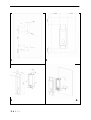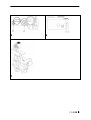
1
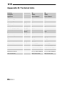
Torch framed
40010567 - 0602
UK
Installation Guide
IRL
1
3
1<<<<
2
4
5
6
7
>>>>2
Content
1
Introduction ......................................................................................... 1
2
Safety Instructions.................................................................................. 2
3
Installation requirements ......................................................................... 3
4
5
6
3.1
Rear surface construction .................................................................. 3
3.2
Dimensions of the appliance ............................................................... 3
Installation-instructions ........................................................................... 4
4.1
Gas connection ............................................................................... 4
4.2
Installing the appliance ..................................................................... 4
Commissioning (Functional checks).............................................................. 5
5.1
Pilot ignition check .......................................................................... 5
5.2
Check functional burner and pilot burner................................................ 5
Servicing ............................................................................................. 6
6.1
Routine servicing ............................................................................. 6
6.2
Combustion test .............................................................................. 7
Appendix A: Spare parts ................................................................................ 8
Apppendix B: Technical data........................................................................... 9
3<<<<
UK
IRL
1 Introduction
Note: these instructions should be read carefully and retained for future reference. Please
leave these instructions with the user.
This guide covers the following appliances:
•
Torch framed
•
Torch framed Propane (LPG)
Special features:
•
Special patented “Torch” flame technology
•
Multi-vent appliance for wall connection only
•
Remote Control option available
•
Meets the essential requirements of the European Gas Appliance Directive (GAD)
and carries the CE mark
1<<<<
UK
IRL
2 Safety Instructions
Before installation, ensure that the local distribution conditions (identification of the type
of gas and pressure) and the adjustment of the appliance are compatible.
This gas appliance is factory set and can not be adjusted.
This appliance does not contain any component manufactured from asbestos or any
asbestos related products.
The pilot and flame sensing device fitted to this fire is also a safety device. If for any
reason any part of the pilot assembly is to be replaced, the entire assembly, including the
pilot burner, thermocouple, electrode and injector, must be exchanged complete for a
pilot assembly from the original manufacturer only.
Ventilation
This appliance is room-sealed and doesn't require purpose provided ventilation.
Never use the appliance if it has a broken glass.
General safety
It is the law in the UK that all gas appliances, are installed by a competent person in
accordance with the Gas Safety (Installation and Use) Regulations (as amended), the
relevant British Standards for Installation work, Building Regulations, Codes of Practice and
the manufacturers instructions.
Always use an additional guard if there are elderly, infirm or children in the same room of
the appliance.
The installation should also be carried out in accordance with the following where
relevant:
•
BS5871 Part1
•
BS5440 Parts 1 & 2
•
BS1251
•
Building Regulations Document J (as applicable)
•
Building Regulations and Standards issued as relevant by the Department of the
Environment or the Scottish Development Department
•
In the Republic of Ireland installation should be carried out in accordance with
IS813, ICP3, IS327, Building Regulations, Codes of Practice, the manufacturers
instructions and all other regulations in force
Failure to comply with the above could leave the installer liable to prosecution and
invalidate the appliance warranty.
>>>>2
UK
IRL
3
Installation requirements
Note: Since the appliance is a source of heat, circulation of air occurs. Therefore it is of
importance that you do not use the appliance shortly after a renovation of the home.
Because of the natural circulation of air, moist and volatile components from paint,
building materials, carpet etc. will be attracted. These components can settle themselves
down onto cold surfaces in the form of soot.
As on all heat producing appliances, soft furnishings such as blown vinyl wallpaper placed
too near to the appliance may become scorched or discoloured. This should be born in
mind when installing the appliance.
3.1
Rear surface construction
The rear wall upon which the appliance is to be fixed must meet these general
requirements:
•
The rear wall must be of a non-combustible material (see figure 1 for drilling
patern)
•
Minimum distance from the back of the appliance to the wall has to be 22mm. This
gap should be maintained by the mounting brackets which fit flush onto the rear
wall
•
The plaster has to be resistant to a high temperature. Therefore use plaster
materials especially made for this, to prevent discolouring (min. 100°C temperature
resistance)
•
Make sure any plaster dries well before using the appliance. Let the thickness in
mm be the number of days the plaster has to dry, e.g. 3mm plaster has to dry for 3
days
•
Although the appliance is tested for installation without a hearth, the appliance
must not stand on combustible materials or carpet
•
Do not place any material directly onto the appliance
•
Minimum distance to any combustible material should be either 200 mm or 400 mm
(see figure 2)
3.2
Dimensions of the appliance
For the dimensions of the appliance see figure 3.
3<<<<
UK
IRL
4 Installation-instructions
4.1
Gas connection
•
Installation pipes should be in accordance with BS 6891. Pipe work from the meter
to the appliance must be of adequate size
•
The complete installation including the meter must be tested for soundness and
purged as described in the above code
•
A means of isolation must be provide in the supply to facilitate servicing
•
The connection should be made in 8 mm copper or similar semi flexible tube (max 1
meter). Ensure that the gas pipe does not interfere with the removal or
replacement of the burner tray of the controls
•
The gas connection is nut and olive suitable for 8 mm pipe
Make sure there is a gas connection with a diameter of 8 mm goes directly from the gas
meter to the appliance, with a CE-approved sealing valve G 1/2". This valve has to be
accessible at all times. Check the connection for gas leaks.
Mount the supplied nut and olive of 8 mm directly on the gas unit. Then you can go on
installing a fixed or flexible connection. This has to be CE certified.
When installed as described above, the burner can always be disassembled for servicing.
4.2
Installing the appliance
•
Check if the wall is sufficiently level. If necessary, improve it
•
Insulate the back wall (if necessary) with promatect or comparable inflammable
material
•
Position the saddle and mark the hole centres on the rear wall, drill the wall and
attach saddle using three screws and nylon inserts (see figure 1 and 2)
•
Place the appliance on the Saddle, mark the hole centres for the Top Clamps (see
figure 3)
•
Remove the appliance, and drill the holes for the clamps. Using two screws and
nylon inserts fit the clamps to the wall, with the clamps slid up the screws
•
Replace the appliance onto the saddle and attach to the Top Clamps. Insert the
screws to retain the appliance to the saddle
•
Tighten all screws with the Gap behind the appliance maintained and the appliance
level
•
Prepare the gas connection
•
Attach the Front Frame. This sits on the lugs on top of the appliance, and fixes to
the saddle at the bottom using 2 screws (see figure 4)
>>>>4
UK
IRL
5 Commissioning (Functional checks)
Always apply these tests before handing over:
5.1
Pilot ignition check
•
Ignite the pilot light as described in the user manual
•
Check if the pilot burner stays alight
•
Extinguish the pilot burner
5.2
Check functional burner and pilot burner
The appliance is preset to give the correct heat input. No further adjustment is necessary.
Always check the inlet pressure and burner pressure:
•
Turn off the gas valve on the appliance
•
Turn the inlet pressure test point C and apply the manometer
•
Check if the measured pressure is the same as the prescribed pressure
•
Perform this measuring when the appliance burns on full capacity and when only
the pilot ignition burns
•
When the pressure is too low, check if the gas pipes are made of material with the
right diameter
•
When the pressure is too high (more than 5 mBar overpressure) you can’t install the
appliance and you should contact your gas company
•
Always check the burner pressure when the functional pressure is right
•
Open the burner pressure test point D
•
The pressure should match the described pressure. If this is not the case, then
contact the supplier
Note: After checking the burner pressure, the inlet pressure test point has to be shut and
checked for gas-tightness.
5<<<<
UK
6
IRL
Servicing
To ensure safe and efficient operation of the appliance, it is necessary to carry out routine
servicing at regular intervals. It is recommended, that the fire is inspected/serviced by a
competent person at least once a year.
Important: turn off the gas supply before commencing any servicing. Always test for gas
soundness after refitting the appliance.
The appliance and flue connection have to be checked for gas and smoke soundness after
installation.
6.1
Routine servicing
Clean (if necessary):
•
the pilot system
•
the burner
•
the combustion chamber
•
the glass
•
Do the functional tests
•
Check the flue system and terminal on damage and soundness (visual inspection)
6.1.1 Cleaning the glass
Depending on the intensity of use, you can get a deposit on the glass. Normally this can be
removed with an ordinary dry towel. If necessary special ceramic glass cleaner (ceramic
cook-top cleaner) can be used. To clean the glass:
•
Remove the Front Frame
•
Remove the glass in it’s frame
•
Clean the glass. Handle the glass with clean hands, wear gloves if possible
•
To fit the glass, proceed in reverse order. Make sure that:
o
the glass sealing rope is in good condition and makes an effective seal
o
Important: be sure that there are no fingerprints on the glass. They are
burned in the glass when not removed.
6.1.2 Cleaning the combustion chamber and burner
You can clean the combustion chamber with a vacuum cleaner and soft brush.
If the burner is visibly damaged, this can affect the performance of the appliance. If so,
then replace the relevant parts.
>>>>6
UK
IRL
6.1.3 Burner (dis)assembly
•
Turn off the gas supply to the control valve
•
Remove the glass and grid
•
Detach the gas connection
•
Unscrew the two screws under the burner assembly and remove it from the
combustion chamber (see figure 7)
6.2
•
The pilot can be removed by removing the screw in the centre of the pilot
•
Replace parts as necessary and re-assemble
Combustion test
A BS7967 combustion analysis check should be carried out using an analyser to
MantleBS7927 positioned in the outlet.
The performance of the appliance should be checked
6.2.1 Procedure for performance test
Ignite the fire and run at FULL for a minimum of 15 minutes
Record the Carbon Dioxide (CO2) reading at the outlet, most analysers will display this as a
percentage (%)
Repeat test for Carbon Monoxide (CO), this will be measured in Parts Per Million (ppm);
Calculate the combustion ratio (CO/CO2).
Ratio =
CO (ppm) _
CO2 (%) x 1000
This combustion ratio of the emitted gasses should not exceed 0.0015
7<<<<
UK
IRL
Appendix A: Spare parts
Description
Natural gas
Propane
Glass
04510930
04510930
Burner Natural gas
20861096
-
-
20532935
Remote assembly
20604500
20604500
Gasvalve
37003098
37003098
HT Lead
06017301
06017301
Spark electrode
06006500
06006500
Pilot Burner assembly NG
37001030
37001030
Thermocouple
37002041
37002041
Burner Propane
>>>>8
UK
IRL
Apppendix B: Technical data
Country
UK
UK
Categorie
II2H3P
II2H3P
Appliance
Torch framed
Torch framed
Appliance type
C11
C11
Reference gas
G20
G31
2,2
2,2
2
2
37
Input (Nett)
[kW]
Efficiency class
Inlet pressure
[mbar]
20
Gasrate (15 C & 1013 bar)
[m3/h]
0,260
[kg/h]
Injector size
[mm]
0,16
1.20
0.8
Type
SIT 145
SIT 145
Code
Nr. 30
Nr. 15
150/100
150/100
Gas control
Mertik GV36
Mertik GV36
Remote control
Mertik G30-ZRPS/800
Mertik G30-ZRPS/800
Batteries remote
1x 9V MN1604 6LR61
1x 9V MN1604 6LR61
Batteries receiver
4x 1,5V LR03 Alkaline
2x 1,5V LR03 Alkaline
Gas connection
8mm nut & olive
8mm nut & olive
Pilot assembly
Outlet terminal size
9<<<<
[mm]
www.faber.nl
–
[email protected]
Saturnus 8
NL - 8448 CC Heerenveen
Postbus 219
NL - 8440 AE Heerenveen
T. +31(0)513 656500
F. +31(0)513 656501
40010567 − 0602