1
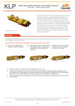
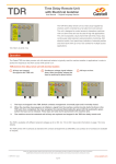
BEMF
Motion Sensing Interlock
User Manual - Original Language Version
The BEMF Motor sensing Interlock is designed to control access
to rotating machinery. The BEMF unit relies on the measurement
of the electromotive force generated by the windings of an
electric motor. Only when the motor has stopped will the BEMF
drop to zero and allow the release of a Castell key. The unit is
used for connection to AC and DC motors including DC braking
systems. The BEMF has been designed to provide the highest
level of safety when installed as part of an access control system
for dangerous machinery.
BEMF-FSB-F-3-110A
Operation
The Castell BEMF switch disconnector is typically used for machine isolation in applications in order to protect the hazardous
area from access while power is on.
BEMF Switch Disconnesctor
1
Power is on, key is trapped. Red
LED is illuminated.
2
Turn the key to OFF position. At zero
movement detection a signal is sent
to the BEMF to energise the solenoid.
A green LED is illuminated. Release
the key by pushing the green button.
3
Key is released, power is off and
the motor stands still.
1.
While the power is on and a motor is running, the key is trapped in the BEMF motor sensing interlock. A red
LED is illuminated.
2.
Turn the key to OFF position to switch the power off. A movement detector gives a signal to the BEMF unit
once zero movement has been detected. This will illuminate a green LED. The key can now be released by
pushing the green button. This key can be taken to unlock the access lock on the motor unit.
3.
The motor stands still and power is off until the key is replaced in the BEMF motor sensing unit.
While every effort has been made to ensure the accuracy of the information provided, no liability can be taken for any errors or omission.
Castell Safety International Limited reserves the right to alter specifications and introduce improvements without prior notice.
www.castell.com
U-BEMF-001-E Issue 2
1 of 7
BEMF
Motion Sensing Interlock
User Manual - Original Language Version
Usage
The BEMF motor sensing unit is designed to be part of a safety system and is used to switch off the power and detect zero
motor movements before releasing a key which is then used to gain access to a hazardous area via an access interlock such as
the AI or Salus.
The BEMF motor sensing unit is not designed for security purposes.
Installation
The BEMF motor sensing unit should be mounted to a surface using suitable fasteners (please refer to drawing on page 4 for
more details). The lock face should be sealed to the panel for ingress protection.
Cables should be connected to the switch in accordance with the applicable wiring diagrams. Ensure that the unit is bonded for
earth continuity (please refer to drawing on page 4 for more installation details).
IMPORTANT:
The interlock should be mounted using anti-tamper fasteners to prevent unauthorised removal.
The BEMF range of motor sensing units must be installed by a competent and qualified person who has read and understood these instructions. Please retain this document in your technical file.
Maintenance
Periodic visual checks should be carried out by the site manager / safety officer.
Do not lubricate lock barrel with oil or grease, use CK Dry Powder Graphite if necessary.
In case of defects beeing detected please contact your nearest Castell Support Department for further actions.
Please see Contact section for contact details.
While every effort has been made to ensure the accuracy of the information provided, no liability can be taken for any errors or omission.
Castell Safety International Limited reserves the right to alter specifications and introduce improvements without prior notice.
www.castell.com
U-BEMF-001-E Issue 2
2 of 7
BEMF
Motion Sensing Interlock
User Manual - Original Language Version
Technical Data
Minimum: -5ºC [23ºF]
Temperature
Maximum: 55ºC [131ºF]
Type of mounting
Surface mount using suitable fasteners (please refer to drawing on page 4 for more details)
Millimeters: 240mm(H) x 140mm(W)
Attachment
Inches: 9.45”(H) x 5.51”(W)
Weight
5.0 kg
Material
Brass or Stainless steel lock portions, powder coated mild steel enclosure
Standards
EN60439-1 ,EN954
Cable Size
M20 Gland x 2
IP Rating
IP65, NEMA 4 enclosure
Standards
standstill detection components to UL (US, Canada)
Contact Rating
Continuous, unattended, remote
Use
Motor switch, circuit-breaker or control switch
Voltage
24 VDC and 240 VAC, 120 VAC
Max Motor Voltage
600V
Max Power Consumption
20VA / 18W
Application
The BEMF is designed to operate as part of an integrated safety system.
The BEMF controls access to hazardous areas with rotary machinery.
When the electric motor is running, the key of the BEMF interlock cannot be
removed, hence preventing access to the hazardous area. To gain access
to the area, the electrical motor must be switched off by turning the key
to OFF position. This changes the switches of the electrical supply to the
machine to a safe condition. A movement sensing detector sends a signal to
the BEMF unit once a zero movement of the motor has been stated. A green
LED illuminates. By pushing the green button, the key can now be removed
and taken by the personnell to the AI access interlock.
The guard can only be opened when the electrical supply has been switched
into a safe condition.The machine cannot be restarted until the door is
closed and the key is removed and taken to the BEMF motor sensing unit.
EC-Declaration
We, the manufacturers, declare that the components, detailed herein and placed on the market, comply with all the essential
health and safety requirements applying to them.
Empowered signatory:
Mr T.C. Whelan
Managing Director
While every effort has been made to ensure the accuracy of the information provided, no liability can be taken for any errors or omission.
Castell Safety International Limited reserves the right to alter specifications and introduce improvements without prior notice.
www.castell.com
U-BEMF-001-E Issue 2
3 of 7
BEMF
Motion Sensing Interlock
User Manual - Original Language Version
Drawing
Dimensions:
Note: For safe mounting, use security screws
in mm
BEMF
While every effort has been made to ensure the accuracy of the information provided, no liability can be taken for any errors or omission.
Castell Safety International Limited reserves the right to alter specifications and introduce improvements without prior notice.
www.castell.com
U-BEMF-001-E Issue 2
4 of 7
BEMF
Motion Sensing Interlock
User Manual - Original Language Version
Wiring Diagram
3 Phase Motor With Star Delta Starting
MC1: High Speed Rotation
MC2: Low Speed Rotation
MC3: Star
Motors With Switched Winding
Motors with star delta starting or
motors with switched windings must be
connected the same as a single phase
motor as shown opposite in order to
avoid interruption in the input circuit.
Otherwise the unit will see this as a
broken wire.
For motors with reversing circuit and
multi speed motors please follow the
same procedure. Whenever 3 phase
connections are switched over, if
interruption is greater then 2 sec, the
BEMF unit will detect broken wire
condition. In order not to store this failure
the unit should be set as auto reset (i.e.
link terminal X2 & X3 of BEMF relay)
3 Phase Motor With Variable Speed Drive
Operation With Electronic Motor
Controller
When there are inverters in the
installation, it is recommended to use
screened cables to the motors. The
screen can be connected to the motor
housing.
While every effort has been made to ensure the accuracy of the information provided, no liability can be taken for any errors or omission.
Castell Safety International Limited reserves the right to alter specifications and introduce improvements without prior notice.
www.castell.com
U-BEMF-001-E Issue 2
5 of 7
BEMF
Motion Sensing Interlock
User Manual - Original Language Version
Wiring Diagram
3 Phase Motor Direct on Line (DOL)
AC Single Phase or DC Motor
Operation With DC Motors
The connection is made similar to single
phase motor. DC motor generate a
remanence voltage during run down
and unit will detect this as broken wire.
In order not to store this failure the unit
should be set as auto reset (i.e. link
terminal X2 & X3 of BEMF relay)
While every effort has been made to ensure the accuracy of the information provided, no liability can be taken for any errors or omission.
Castell Safety International Limited reserves the right to alter specifications and introduce improvements without prior notice.
www.castell.com
U-BEMF-001-E Issue 2
6 of 7
BEMF
Motion Sensing Interlock
User Manual - Original Language Version
Order Information
Product Type
1
Part Number
BEMF
-
Example
BEMF
-
2
3
4
FS
B
-
F
5
6
110
A
-
-
3
-
7
ABC
1
Lock portion type
FS (1) / Q (1)
2
Material
B = Brass (standard)
3
Mounting
F = Front of board mount, with enclosure (standard)
4
Number of poles
3, standard
5
Voltage
24 / 110 / 240 (standard)
6
Current
AC (use for 110V and 240V) / DC (use for 24V)
7
Lock portion symbol
FS(1) up to 3 characters / Q(1) up to 6 characters
(1)
FS - Lock type
Q - Lock type
Up to 3 characters Up to 6 characters
Special construction available upon enquiry
Accessories
Product
Part number
Flip Cap
FLIP-S
Contact Information
Castell Safety International Ltd.
The Castell Building
217 Kingsbury Road
London, England NW9 9PQ
Castell Safety International Ltd.
Oskar-Jäger-Strasse 137
50825 Köln
Germany
Castell Interlocks Inc.
Suite 800
150 N Michigan Avenue,
Chicago, Illinois 60601
USA
Castell Safety China
Building 1, No. 123,
Lane 1165, Jindu Road,
Minhang District,
Shanghai 201108, China.
t: +44 (0) 20 8200 1200
f: +44 (0) 20 8905 9378
e: [email protected]
t: +49 (0) 221 1694 794
f: +49 (0) 221 1694 795
e: [email protected]
t: +1.312.360.1516
f: +1.312.268.5174
e: [email protected]
t: +86 21 61519023
f: +86 21 61519030
e: [email protected]
While every effort has been made to ensure the accuracy of the information provided, no liability can be taken for any errors or omission.
Castell Safety International Limited reserves the right to alter specifications and introduce improvements without prior notice.
www.castell.com
U-BEMF-001-E Issue 2
7 of 7