1
Advanced 3 Million Wireless USB Underbody Kit & Wheel Well Lights
Warning: Please check your state and local laws before installing this LED underbody kit. Every state has different policies and procedures in
place regarding aftermarket vehicle accessories. LEDGlow is not responsible for any fines that you may receive while using this underbody kit.
This kit is for off road use only.
Warning: The installation of this kit is recommended to be installed by a licensed professional. The improper installation of this kit will void
all warranties.
The control box that is used to power the underbody and wheel well tubes must be installed in a dry location! Having this part exposed
to water or the elements will cause the kit’s controller to fail. Any water damage or corrosion to this part will VOID all warranties.
PLEASE READ THE FOLLOWING INSTRUCTIONS THOROUGHLY BEFORE INSTALLING AND OPERATING THIS LED
UNDERBODY KIT.
Underbody & Wheel Well Kits Include:
(2) 48 Inch Underbody Tubes
(2) 36 Inch Underbody Tubes
(4) 24 Inch Wheel Well Tubes
(1) Control Box
(1) Wireless Remote
(2) USB Hubs
(1) USB Linking Cable
(14) Mounting Brackets
(25) Zip Ties
(30) Large Screws
Underbody Kit Installation:
1.
Arrange the tubes out on the ground and test the kit to ensure proper functionality before installing.
2.
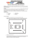
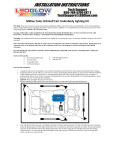
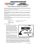
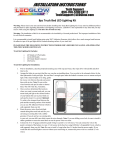
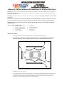
Before mounting the underbody tubes, please refer to the schematic below. The underbody tubes on this kit must be
installed in a specific way. This ensures all lighting patterns are properly synchronized and displayed correctly.
Note: The tubes can be plugged into any of the ports on the USB hub and will not affect the patterns.
3.
Optional: Raise and support the vehicle.
4.
First, mount the front 36 inch tube with the red sticker to your vehicle using the included mounting brackets and zip ties. Make
sure the tube’s USB connector is facing the passenger side of the vehicle and is at least 8 inches away from any direct heat
source and away from all moving parts. Use the included zip ties to secure the underbody tube to the mounting bracket.
IMPORTANT: DO NOT MOUNT THE TUBE TO THE RADIATOR.
5.
Then, mount the driver’s side 48 inch tube with the green sticker to your vehicle using the included mounting brackets and zip
ties. Make sure the tube’s USB connector is facing the rear of the vehicle. A good mounting location for this tube is either to the
pinch well or side skirt. Be extremely aware of the location of brake lines and fuel lines and do not mount the underbody
tube too close to the exhaust. Leave at least 8 inches between the exhaust and the underbody tube. Keep the tube and the
power wire away from any moving parts. Use the included zip ties to secure the underbody tube to the mounting bracket.
6.
Next, mount the passenger’s side 48 inch with the blue sticker to your vehicle using the included mounting brackets and zip ties.
Make sure the tube’s USB connector is facing the rear of the vehicle. A good mounting location for this tube is either the pinch
well or the side skirt. Be extremely aware of the location of brake lines and fuel lines and do not mount the underbody
tube too close to the exhaust. Leave at least 8 inches between the exhaust and the underbody tube. Keep the tube and the
power wire away from any moving parts. Use the included zip ties to secure the underbody tube to the mounting bracket.
7.
Now, mount the rear 36 inch tube with the white sticker to your vehicle using the included mounting brackets and zip ties. Make
sure the tube’s USB connector is facing the driver side of the vehicle. Be extremely aware of the location of brake lines and
fuel lines, and do not mount the underbody tube too close to the exhaust. Leave at least 8 inches between the exhaust and
the underbody tube. Keep the tube and the power wire away from any moving parts. Use the included zip ties to secure the
underbody tube to the mounting bracket.
8.
Find a safe, secure and dry place to mount the USB junction box. We recommend mounting the junction box inside of the
car, if possible. If this is not possible, we suggest mounting the USB junction box under the hood in the driest location available.
Optional: For extra protection, apply a thin layer of silicone along the seams of the junction box to seal it.
9.
Connect the red power wire to a 12 volt source. If you need to extend the power wires, be sure to only use 16 or 18 gauge
automotive grade wiring. If you are running the power wire to the battery, it must go through the fire by using an existing
grommet or by drilling a hole and adding a new grommet, which is available at any auto parts store. Be sure to install the fuse
within 6 inches of the power source. If you connect the power wire to a switched 12 volt source, the underbody kit may not
remember the previous color and pattern it was last on before turning off the vehicle. If you connect the power wire to a constant
12 volt source, the underbody kit will remember the previous color and pattern it was on prior to powering the vehicle down.
You can also power this kit directly from your vehicle’s fuse box by using LEDGlow’s Expandable Circuit that is available at
www.LEDGlow.com
10. Connect the black wire to a good unpainted ground source. A couple of good ground sources are under the dash at any main
bracket or grounding block, the negative terminal on your battery or any engine ground.
11. Beginning with the rear tube, run the wire to the location of the USB junction box. Make sure to secure the wires tightly when
going around the suspension and/or exhaust. Leave at least 8 inches between the exhaust and the underbody tube. Run the rear
tube’s power wire along one of the side tubes and make sure it is tightly secured. Next, run both side tubes power wires to the
USB junction box and lastly, run the front tube’s power wire to the USB junction box.
12. It is imperative to make sure that the wires are not mounted to any direct hear source or to any moving parts. Any excess length
on the tube power wire will have to be bound up and secured tightly.
13. DO NOT SHORTEN OR CUT ANY OF THE UNDERBODY TUBE POWER WIRES. THIS WILL DESTROY THE
KIT AND VOID ALL WARRANTIES.
14. Lower the vehicle if it was raised, power the kit and test it for full functionality.
15. Once the vehicle is on the ground, turn the steering wheel as far as it can go in both directions to ensure the tube and/or wires are
not coming in contact with your tires or any other moving parts.
Wheel Well Installation:
1.
Arrange the tubes out on the ground and test the wheel well tubes to ensure proper functionality before installing.
2.
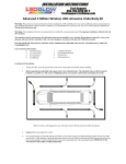
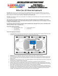
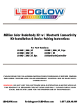
Before mounting each tube, please refer to the schematic below to ensure correct placement and tube direction. Note: The tubes can
be installed either behind the strut facing the rim or above the tire to the fender well. The connectors for each tube must be
facing the rear of the vehicle. When running the wires to the USB hub, be sure to keep them away from any moving parts and
at least 6 inches from any direct heat source.
3.
Once the kit has been laid out properly and you have determined it is functioning properly, you can proceed with the rest of the
installation.
4.
First, mount the driver’s side front tube with the green sticker to your wheel well, either behind the strut or above your tire to the
fender well. Make sure the USB connector is facing the rear of the vehicle using the included self-tapping screws through the end caps
on each tube. Make sure the tube is at least 6 inches away from any direct heat source and away from all moving parts. Use the
included wire ties to secure all excess wire.
5.
Second, mount the passenger’s side front tube with the green sticker to your wheel well, either behind the strut or above your tire to
the fender well. Make sure the USB connector is facing the rear of the vehicle using the included self-tapping screws through the end
caps on each tube. Make sure the tube is at least 6 inches away from any direct heat source and away from all moving parts.
Use the included wire ties to secure all excess wire.
6.
Next, mount the passenger’s side rear tube with the blue sticker to your wheel well, either behind the strut or above your tire to the
fender well. Make sure the USB connector is facing the rear of the vehicle using the included self-tapping screws through the end caps
on each tube. Make sure the tube is at least 6 inches away from any direct heat source and away from all moving parts. Use the
included wire ties to secure all excess wire.
7.
Next, mount the driver’s side rear tube with the blue sticker to your wheel well, either behind the strut or above your tire to the fender
well. Make sure the USB connector is facing the rear of the vehicle using the included self-tapping screws through the end caps on
each tube. Make sure the tube is at least 6 inches away from any direct heat source and away from all moving parts. Use the
included wire ties to secure all excess wire.
8.
Now, connect one of the male ends of the USB linking cable to the USB hub with underbody tube connections and the other male end
of the linking cable to the USB hub that came with the wheel well kit. Now that both USB hubs are linked, plug the USB connections
from the wheel well tubes to the USB hub.
9.
Mount the wheel well kit’s USB hub in a safe and secure location inside of your vehicle or to your vehicle’s fire wall away from any
direct heat source in a dry location. Run the USB hub’s cable from the firewall through a pre-existing hole with a grommet in your
firewall. If you do not have a pre-existing hole in the firewall, you can drill one, just be sure to use a rubber grommet to ensure the
lead wire is not cut or pinched.
10. It is imperative to make sure that the wires are not mounted to any direct hear source or to any moving parts. Any excess length on the
tube power wire will have to be bound up and secured tightly.
11. DO NOT SHORTEN OR CUT ANY OF THE WHEEL WELL TUBE POWER WIRES. THIS WILL DESTROY THE KIT
AND VOID ALL WARRANTIES.
12. Lower the vehicle, if it was raised, power the kit ON and test the underbody and wheel well kits for full functionality.
13. Once the vehicle is on the ground, turn the steering wheel as far as it can go in both directions to ensure the tube and/or wires are not
coming in contact with your tires or any other moving parts.
Note: The control box features a built in sound activation mode that will pick up the vibrations from the music playing inside of your vehicle.
Turning this mode ON and OFF is explained in the “Using the Control Box” section of these instructions below.
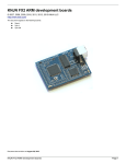
Using the Control Box
Turning the Kit ON and OFF
Using the Control Box
To turn the kit ON, press and hold the P1 button for 3 seconds.
To turn the kit OFF, press and hold the P1 button for 3 seconds
Using the Wireless Remote
To turn the kit ON, press and hold the
To turn the kit OFF, press and hold the
button for 3 seconds.
button for 3 seconds.
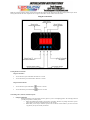
Customizing Colors, Patterns, and Pattern Speed
P1 Button and Display
o
Pressing the P1 button cycles through the 10 factory presets or your 10 saved lighting patterns. The P1 display will show
you what preset pattern is currently active.
Note: This underbody kit includes a real time auto save feature. Whenever any changes are made to a preset
pattern and/or color, this kit will automatically save the changes.
Note: When you are ready to customize a preset be sure to select the correct number so you do not overwrite
any patterns you may have already customized.
P2 Button and Display
o
o
Pressing the P2 button allows you to change the various options within the selected pattern.
Press and hold this button for 2 seconds to activate. Release this button when the number “1” flashes in the P2
position on the display.
To select and move to the next option, simply press the P2 button again.
Note: Once an option is changed, pressing this button again to change another setting will not affect your
previous selection.
Note: The sound activation mode is on this kit is preset to the on position. If your patterns are not functioning
properly, ensure that the sound activation mode is turned off by referencing the “Sound Activation Mode”
section of the instructions.
What each P2 number displayed on the control box represents:
1 – Pattern Selection
1. This allows you to select from 19 customizable patterns using the P3 and P4 buttons.
2. Note: When this is set to 0, no pattern is selected.
2 – Pattern Speed
1. This allows you to select the speed of the pattern using the P3 and P4 buttons.
2. Speed range is from 0 to 19.
3 – Primary Color Setting
1. Selects the Primary Color displayed on the kit.
2. This allows you to select from 19 preset color modes using the P4 button. The colors are listed
below. Note: The number before each color represents the number displayed on the P4 portion of the
control box. Setting this kit to a solid color mode or creating your own color is explained below.
2 – Multi Color Mode
3 – Red
4 – Green
5 – Blue
6 – Yellow
7 – Purple
8 – Teal
9 – White
10 – 7 Color Fade Mode
11 – Slow Red Fade
12 – Slow Green Fade
13 – Slow Blue Fade
14 – Slow Yellow Fade
15 – Slow Purple Fade
16 – Slow Teal Fade
17 – Slow White Fade
18 – Slow 7 Color Fade
19 – Million Color Fade Mode
4 – Secondary Color Fade Speed
1. This allows you to control the speed of the secondary color fade in certain patterns using the P3 and
P4 buttons.
2. Fade range is from 0 to 19.
3. A pattern with primary and secondary color options must be selected in order to use this option.
5 – Changes the Secondary Color
1. This allows you to change the color of the secondary pattern using the P4 button
2. Secondary color numbers correspond with primary color numbers.
3. A pattern with primary and secondary color options must be selected in order to use this option.
6 – Secondary Pattern Speed
1. This allows you to change the speed of the secondary color that is running through the primary color
using the P3 and P4 buttons.
2. Speed range is from 0 to 19.
3. A pattern with primary and secondary color options must be selected in order to use this option.
7 – Sound Activation Mode
1. This allows you to put this kit into a sound activation mode using the P4 button.
2. Setting to 0 turns the sound activation mode OFF.
3. Setting to 1 turns the sound activation mode ON.
4. Important: Sound activation is defaulted to the ON position. If your patterns are not working
correctly, ensure that this setting is set to 0.
8 – Sound Activation Mode Sensitivity
1. Allows you to change the sensitivity of the sound activation mode using the P3 and P4 buttons.
2. Sensitivity range is from 0 to 9.
P3 and P4 Buttons and Display
o
o
o
Pressing these buttons allows you to cycle through options.
P3 cycles down through the options.
P4 cycles up through the options.
Setting the Kit to a Solid Color and Creating Custom Solid Colors
o
Setting the Kit to a Solid Color Mode
o
Press the P1 button to your desired preset number.
Once you have selected your desired preset position, press and hold the P2 button until the “1” flashes on the
control box display.
Now that the number “1” is flashing in the P2 position on the display, press the P3 button until the display reads
0 in the P4 position.
Now press the P2 button until a “3” is flashing in the P2 position on the control box display
Once a “3” is displayed in the P2 position on the control box display, you can press the P4 button to cycle
through all solid color modes. Note: Reference the numerical chart above for each solid color mode display
number.
Creating a Custom Solid Color
Restoring the Kit Back to Factory Settings
o
o
You must be in the Solid Color Mode explained above to create custom colors. Once you are in the solid
color selecting the mode explained above, press the P4 button until a “19” is displayed in the P4 position on the
control box display. This will put the kit into a Million Color Fade Mode.
While you are in this mode, you can press the P3 button any time to pause the kit when you find your desired
color. The auto save feature will automatically save your color to your selected preset number.
1. Note: You can double press the P3 button to slowly step between each color, giving you more
control over your color selection.
2. Note: Your custom color will automatically save to the preset number you selected on the P1
display.
Turn the kit off, then press and hold the P4 button for 3 seconds.
When the display is flashing with a “1”, the factory defaults have been restored.
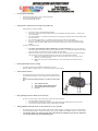
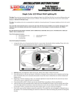
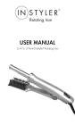
Wireless Remote Functions
o
o
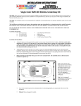
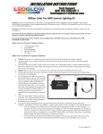
The included wireless remote only allows you to turn the kit ON/OFF,
cycle through saved patterns, as well as put the kit into Sound Activation
Mode.
Note: To customize patterns and colors, you MUST use the Control
Box.
1.
2.
3.
4.
Reprogramming the Wireless Remote to the Control Box
o
Powers the Kit ON/OFF
Turns Sound Activation Mode ON/OFF
Cycles Through Preset/Saved Patterns
Not Used
If you lost or need to replace your wireless remote, follow the instructions below:
Turn the kit OFF by pressing the P1 button.
Press and hold the #3 button on the wireless remote while holding the P2 button down on the control box.
The control box will quickly flash “0000” on the display if successful.
Adding Additional Underbody, Interior or Wheel Well Tubes to your Control Box
o
o
o
This underbody kit can power and unlimited amount of add-on tubes whether it is underbody, interior or wheel well tubes.
To power the additional tubes, simply connect them to your existing USB hub. Each USB hub can power a total of 6 tubes.
Note: If all the USB ports are being used on the hub, connect the add-on USB hub that came with your add-on kit to
your existing USB hub using the included linking cable.
ONE YEAR NON-TRANSFERRABLE LIMITED WARRANTY AND DISCLAIMER
LEDGlow Lighting, LLC ("LEDGlow") warrants to the original retail consumer purchaser, and not any other purchaser or subsequent owner, that this Product will be free from defects in
material or workmanship for a period of one (1) year from the purchase date. This warranty does not cover any Product that is (1) installed incorrectly, or (2) damaged by collisions,
vandalism, other accidents, or similar causes.
For a period of one (1) year from the date of purchase, at no charge to the Purchaser, LEDGlow will repair or replace this Product if it is determined by LEDGlow to be defective. After the
warranty period, the Purchaser must pay all charges for parts and labor.
Coverage under this warranty is only valid within the United States, including its territories, as well as in certain other countries. Purchasers should check our website, www.LEDGlow.com, to
determine the warranty coverage in the countries in which they are located.
LEDGlow does not warrant the installation of the Product, which is the sole responsibility of the Purchaser. Installation should be done by licensed professionals. Improper installation may
cause damage to the Product and any vehicle in which it is installed, and may cause burns and electrical injury to individuals. LEDGlow’s warranty does not cover any expenses incurred in
removing Products that are defective or re-installing replacement Products in their place.
During the warranty period, to have the Product repaired or replaced, the Purchaser must return the Product, freight prepaid by the Purchaser, to LEDGlow (but for customers in the contiguous
United States, LEDGlow will pay the shipping charges if any Product fails during the first thirty (30) days after purchase). The Product must be returned in its original carton or in a similar
package affording an equal degree of protection. LEDGlow will return the repaired or replaced Product, freight prepaid, to the Purchaser. LEDGlow does not provide Purchasers with temporary
replacement units during the warranty period or at any other time.
This limited warranty is non-transferrable and will automatically terminate if the original retail consumer purchaser resells the Product or transfers the vehicle on which the Product is installed.
An “original retail consumer purchaser” is a person who originally purchases the Product, or a gift recipient of a new Product that is in its original packaging and unopened.
This limited warranty is subject to all of the following terms and conditions:
TERMS AND CONDITIONS
1. NOTIFICATION OF CLAIMS; WARRANTY SERVICE: IF PURCHASER BELIEVES THAT A PRODUCT IS DEFECTIVE IN MATERIAL OR WORKMANSHIP, WRITTEN
NOTICE WITH AN EXPLANATION OF THE CLAIM SHALL BE GIVEN PROMPTLY BY PURCHASER TO LEDGLOW. ALL WARRCANTY CLAIMS MUST BE MADE WITHIN
THE WARRANTY PERIOD, AND ANY PRODUCTS RETURNED TO LEDGLOW MUST BE SHIPPED IN ACCORDANCE WITH LEDGLOW’S PROCEDURES (INCLUDING USE OF
RMA NUMBERS SUPPLIED BY LEDGLOW AFTER NOTIFICATION). THE REPAIR OR REPLACEMENT OF ANY PRODUCT OR PART THEREOF SHALL NOT EXTEND THE
ORIGINAL WARRANTY PERIOD. THE SPECIFIC WARRANTY ON THE REPAIRED PART ONLY SHALL BE IN EFFECT FOR A PERIOD OF NINETY (90) DAYS FOLLOWING
THE REPAIR OR REPLACEMENT OF THAT PART, OR THE REMAINING PERIOD OF THE PRODUCT WARRANTY, WHICHEVER IS GREATER.
2. EXCLUSIVE REMEDY; ACCEPTANCE: PURCHASER'S EXCLUSIVE REMEDY AND LEDGLOW'S SOLE OBLIGATION IS TO SUPPLY (OR PAY FOR) ALL LABOR
NECESSARY TO REPAIR ANY PRODUCT FOUND TO BE DEFECTIVE WITHIN THE WARRANTY PERIOD AND TO SUPPLY NEW OR REBUILT REPLACEMENTS FOR
DEFECTIVE PARTS. LEDGLOW WILL REFUND THE PURCHASE PRICE FOR SUCH PRODUCT ONLY IF REPAIR OR REPLACEMENT FAILS TO REMEDY THE DEFECT.
PURCHASER'S FAILURE TO MAKE A CLAIM AS PROVIDED IN PARAGRAPH 1 ABOVE OR CONTINUED USE OF THE PRODUCT SHALL CONSTITUTE AN UNQUALIFIED
ACCEPTANCE OF SUCH PRODUCT AND A WAIVER BY PURCHASER OF ALL CLAIMS THERETO.
3. EXCEPTIONS TO LIMITED WARRANTY: LEDGLOW SHALL HAVE NO OBLIGATION TO PURCHASER WITH RESPECT TO ANY PRODUCT THAT IS SUBJECTED TO
ANY OF THE FOLLOWING: ABUSE, IMPROPER USE, NEGLIGENCE, ACCIDENT, MODIFICATION, FAILURE TO FOLLOW THE OPERATING PROCEDURES OUTLINED IN
THE USER'S MANUAL, FAILURE TO FOLLOW THE MAINTENANCE PROCEDURES IN THE SERVICE MANUAL FOR THE PRODUCT, ATTEMPTED REPAIR BY NONQUALIFIED PERSONNEL, OPERATION OF THE PRODUCT OUTSIDE OF THE PUBLISHED ENVIRONMENTAL AND ELECTRICAL PARAMETERS, OR IF THE PRODUCT'S
ORIGINAL IDENTIFICATION (TRADEMARK, SERIAL NUMBER) MARKINGS HAVE BEEN DEFACED, ALTERED, OR REMOVED. LEDGLOW EXCLUDES FROM WARRANTY
COVERAGE PRODUCTS SOLD AS IS AND/OR WITH ALL FAULTS. LEDGLOW ALSO EXCLUDES FROM WARRANTY COVERAGE ANY CONSUMABLE ITEMS SUCH AS
FUSES AND BATTERIES.
All software and accompanying documentation furnished with, or as part of the Product is furnished “AS IS” (i.e., without any warranty of any kind), except where expressly provided otherwise
in any documentation or license agreement furnished with the Product.
4. PROOF OF PURCHASE; REGISTRATION: The Purchaser's dated bill of sale must be retained as evidence of the date of purchase and to establish warranty eligibility. Registration of
any Product or of this limited warranty is voluntary, and failure to register will not diminish any rights available under this warranty.
DISCLAIMER OF WARRANTY
EXCEPT FOR THE FOREGOING WARRANTIES, LEDGLOW HEREBY DISCLAIMS AND EXCLUDES ALL OTHER WARRANTIES, EXPRESS OR IMPLIED, INCLUDING, BUT
NOT LIMITED TO ANY IMPLIED WARRANTIES OF MERCHANTABILITY, FITNESS FOR A PARTICULAR PURPOSE, OR ANY WARRANTY WITH REGARD TO ANY CLAIM
OF INFRINGEMENT THAT MAY BE PROVIDED IN SECTION 2-312(3) OF THE UNIFORM COMMERCIAL CODE OR IN ANY OTHER STATE STATUTE.
LIMITATION OF LIABILITY
THE LIABILITY OF LEDGLOW, IF ANY, AND PURCHASER'S SOLE AND EXCLUSIVE REMEDY FOR DAMAGES FOR ANY CLAIM OF ANY KIND WHATSOEVER,
REGARDLESS OF THE LEGAL THEORY AND WHETHER ARISING IN TORT OR CONTRACT, SHALL NOT BE GREATER THAN THE ACTUAL PURCHASE PRICE OF THE
PRODUCT FOR WHICH SUCH CLAIM IS MADE. IN NO EVENT SHALL LEDGLOW BE LIABLE TO PURCHASER FOR ANY SPECIAL, INDIRECT, INCIDENTAL, OR
CONSEQUENTIAL DAMAGES OF ANY KIND INCLUDING, BUT NOT LIMITED TO, COMPENSATION, REIMBURSEMENT OR DAMAGES ON ACCOUNT OF THE LOSS OF
PRESENT OR PROSPECTIVE PROFITS OR FOR ANY OTHER REASON WHATSOEVER.
GOVERNING LAW: This non-transferrable limited warranty shall be governed by the law of the State of New Jersey, U.S.A., and the United States of America, excluding their conflicts of laws
principles. The courts of Camden County, New Jersey, shall have the exclusive jurisdiction over any legal action with respect to this warranty.
This limited warranty gives specific legal rights. You may also have other rights that may vary from state to state or from country to country. Some states or countries do not allow the exclusion
or limitation of incidental or consequential damages, so the above limitations and exclusions may not apply to you. You are advised to consult applicable state or country laws for a full
determination of rights.