1
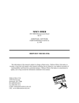
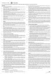
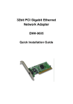
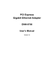
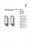
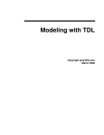
Page 1 of 10
Model 8277
Multimode Fiber Optic Modem
Reference Manual
0315-0292 Rev. F
Printed 11.07.01
Table of Contents
1.0 Equipment Description
1.1
1.2
1.3
1.4
Introduction
Optical Interface
Electrical Interface
Flow Control
2.0 Specifications
2.1
2.2
2.3
Optical Interface
Electrical Interface
General Specifications
3.0 Equipment Operation
3.1
3.2
Switch Options
Connections
4.0 Indicators
5.0 Help
Page 2 of 10
1.0 Equipment Description
1.1 Introduction
The Model 8277 Multi-mode Fiber Optic Modem is an asynchronous product. The optical
interface can operate in either point-to-point or ring configurations and employs two "ST-"
type connections. The unit operates on fiber optic cables with core diameters from 50 to 100
microns.
The electrical interface operates in either point-to-point or multi-drop configurations. When
configured as RS-232 or RS-422 the unit will operate point-to-point. With the RS-485
interface selected, equipment can be multi-drop connected onto low-cost twisted-pair wire
(see Figure 1). The versatility of the two interfaces of the Model 8277 allows for an
extremely flexible system design.
Figure 1 RS-485 Multi-drop Configuration
Page 3 of 10
1.2 Optical Interface
In an optical point-to-point configuration, two Model 8277s are connected back to back to
form a simple, high-speed, full-duplex optical link. In optical ring operation, two or more
8277s are cascaded in a ring. A ring consists of one master modem and two or more slaves
(see Figure 2). The slaves pass received optical data and transmit data from their electrical
interface to their optical transmitters.
The master does not pass received optical data. Master/slave modes are switch selectable.
Master mode is selected for both modems in an optical point-to-point configuration.
Figure 2 Optical Ring
Note: In RS-485 two-wire mode (when configuring the Model 8277 in an optical ring) the
master cannot be enabled by the "TD" signal.
The Model 8277 optical interface can form a ring of up to ten units. This allows for a
maximum optical system loss budget of 120 dB. In order to extend the optical distance
between any two Model 8277s, the units are inserted in the optical path to act as line
extenders. Slave mode should be selected for optical line extenders (see Figure 3).
Figure 3 Extending Optical Distance
Note: The Model 8277 transmits infrared light which is not visible to the eye.
Page 4 of 10
1.3 Electrical Interface
The Model 8277's electrical interface is switch selectable to RS-232 or RS-422/RS-485
voltage levels. When the RS-232 interface is selected, communications to the electrical
interface are full-duplex point-to-point. With this interface, data can be transmitted onto the
optical fiber for a point-to-point optical link or for an optical ring. Switch selection enables
data to flow from the electrical interface to the optical transmitter or can be controlled by a
high on RTS. On the electrical interface, a high on the Data In pin causes light to be emitted.
Full-duplex (four-wire) or half-duplex (four- or two-wire) mode may be selected when the
RS-422/RS-485 interface is selected. The RS-422/RS-485 interface of the Model 8277 can
operate in a multi-dropped or point-to-point environment. If RS-422 mode is selected the
electrical interface is only point to point. If the customer's equipment has an RS-485
interface, it can be multi-dropped directly onto the Model 8277's interface by selecting the
four-wire or two-wire RS-485 mode. If the customer's equipment has an RS-232 interface,
the equipment can be converted to a multi-drop, RS-485 interface by a Telebyte Model 285.
Up to 31 units of the Model 285 can be multi-dropped onto the same electrical interface of
the Model 8277.
1.4 Flow Control
Operation in the RS-485 multi-drop or the ring environment requires that all devices
connected to the line have some level of intelligence in order to establish an orderly flow of
data. When RS-485 (half duplex) mode is selected, the Model 8277 controls the Receive
Data line on the electrical interface. When data is not received (no light on fiber) by the
optical receiver for ten microseconds, the output of the Receive Data electrical transmitter is
tri-stated. In RS-485 mode this enables many transceivers to communicate on the same
twisted pair. When the RS-485 two-wire mode is selected, half-duplex data is transmitted and
received on the same twisted pair.
Note: In RS-485 two-wire mode (when configuring the Model 8277 in an optical ring) the
master cannot be enabled by the "TD" signal.
Page 5 of 10
2.0 Specifications
2.1 Optical Interface
Optical connectors: ST™ (trademark AT & T)
Power Out: > +15 dBuW (32 microWatts), into 62.5/125 um core/clad fiber
Power Budget: > 12 dB on 62.5/125 um core/clad fiber
Wavelength: 850 nm, multi-mode
Optical Configuration: Switch selectable, Master/Slave
2.2 Electrical Interface
Electrical connector: DB-9, male
Interface type:
Switch selectable
RS-232 (pinout conforms to RS-232)
RS-422, or RS-485
Bit Rate:
RS-232: 0 to 115.2 KBPS
RS-4XX: 0 to 1 MBPS
Interface Mode:
Switch selectable. Unit can be configured to appear as a DCE or a DTE.
2.3 General Specifications
Indicators:
Four LEDs
LTD Local Transmit Data
FTD Fiber Transmit Data
RD Receive Data
COL Collision
Power: +12 VDC @ 500ma
Environment: 0 to 50 degrees Celsius
Size: 5" W x 5.3" L x 1.7" H
Page 6 of 10
3.0 Equipment Operation
3.1 Switch Options
The Model 8277 is a versatile unit. It has many switch-selectable options that can be used to
tailor it to different communications requirements. The switches are located on the side
p anels. The following tables list the switch selections and their functions.
Front Panel Switch Option
Switch
Name
DCE/DTE
Function
DCE - Pin 2 is an input into the unit and
Pin 3 is an output
Factory Settings
DCE
DTE - Pin 2 is an output and Pin 3 is the
input into the unit
232
422/485
Selects electrical interface. 232 is RS232 and 422 is RS-422 or RS-485.
232
Bottom Dip Switches
DIP No.
FUNCTION
Factory Settings
1
ON – Connects pin 7 to pin 8 at the
electrical interface.
ON
(CLOSE)
2
ON - Connects pin 4 to pin 9 at the
electrical interface.
ON
(CLOSE)
3
ON – Close to terminate 4XX receiver.
ON
(CLOSE)
4
ON – Close for TDl Xmit Cont.,
Open RTS controls Xmit.
ON
(CLOSE)
5
ON – Close for a 4 wire, 422.
OFF
(OPEN)
6
ON – Close for 2 wire, 485
OFF
(OPEN)
7
ON – Close for 4 wire, 485
OFF
(OPEN)
8
ON – Close for Optical Master, Open
slave
ON
(CLOSE)
Page 7 of 10
3.2 Connections
After the switches have been set properly, the connections to the Model 8277 I/O ports must
be made. There are three groups of connections. These are the fiber optic interface, the
electrical interface and the power interface. A minimum of two Model 8277s is required for
communications.
The connections to the fibers are through two ST connectors on the rear of the Model 8277.
These are marked "T" for optical transmit and "R" for optical receive. The fibers between the
two communicating Model 8277s must be cross connected (i.e., the optical transmitters must
be connected to the optical receivers).
The Model 8277’s optical power budget is specified as 12 dB, using 62/5 um core fiber. The
units may use fibers with other core diameters. The table that follows specifies the loss
budget for the different fibers.
Max. Optical Loss Budget
Core
Max Loss
(um)
(dB)
50
8.6
62.5
12
85
14.3
100
16.2
The connections to the electrical interface are through the DB-9 connector located on the rear
of the Model 8277. The signals on these pins are shown in the tables that follow. These
signals (as well as their functions and directions) vary with the switch settings. Proper
connection requires, at a minimum, the use of TD, RD and GND. The tables that follow
show the signal names and their sources for the various settings of the DCE/DTE switch and
the 232/4XX switch.
The Model 8277 is powered from an external transformer supplied with the unit. The power
transformer is plugged into 115 VAC and converts the 115 VAC to an unregulated DC
voltage to be used by the unit. The connection to the transformer on the Model 8277 is
located on the rear of the unit. A 220 VAC, 50 Hz transformer is available as an ordering
option.
Page 8 of 10
Electrical Interface Pinouts
3
2
7
5
Pin #
2
3
8
5
Pin #
3
1
2
6
7
4
5
Pin #
3
1
2
6
8
9
5
Pin #
3
1
7
4
5
Pin #
2
6
8
9
5
RS-232, Switch in DCE position
Signal
Signal
Signal
Function
Generated by
Generated by Model
Customer
8277
TD
X
RD
X
RTS
X
GND
RS-232, Switch in DTE position
Signal
Signal Generated
Function
by Customer
TD
X
RD
CTS
X
GND
Signal Generated
by Model 8277
X
RS-422/RS-485, 4-wire, Switch in DCE position
Signal
Signal Generated by
Signal Generated
Function
Customer Equipment
by Model 8277
TDX
TD+
X
RDX
RD+
X
RTSX
RTS+
X
GND
RS-422/RS-485, 4-wire, Switch in DTE position
Signal
Signal Generated by
Signal Generated
Function
Customer Equipment
by Model 8277
RDX
RD+
X
TDX
TD+
X
CTSX
CTS+
X
GND
RS-485, 2-wire, Switch in DCE position
Signal
Signal Generated by
Function
Customer Equipment
TD-, RDTDTD+, RD+
TD+
RTSX
RTS+
X
GND
RS-485, 2-wire, Switch in DTE position
Signal
Signal Generated by
Function
Customer Equipment
TD-, RDTDTD+, RD+
TD+
CTS+
X
CTSX
GND
Signal Generated
by Model 8277
RDRD+
Signal Generated
by Model 8277
RDRD+
Note: When connecting to the Telebyte Model 285 the polarities of the TD and RD pins must
be reversed.
Page 9 of 10
4.0 Indicators
There are four LED indicators located on the front panel of the Model 8277. These indicators
can be used to see the status of the Model 8277 and equipment connected to it. Below is a list
of the LEDs and their functions.
LTD (Local Transmit Data)
This LED is used to monitor the data coming into the electrical interface from the user's
equipment. For RS-232 mode, a positive voltage on the data entering the Model 8277 turns
this LED on when either one of the following conditions is met:
a) With the DCE/DTE switch in the DCE position, Pin 3 (TD) will turn on the LED; or b)
With the switch in the DTE position, Pin 2 (RD) will turn on the LED.
For RS-4XX (with the DCE/DTE switch in the DCE position) a voltage more positive on Pin
6 (TD+) than on Pin 2 (TD-) turns this LED on. With the switch in the DTE position the line
monitors are Pin 1 (RD+) and Pin 3 (RD-).
Note: In RS-485 two-wire mode (when configuring the Model 8277 in an optical ring) the
master cannot be enabled by the "TD" signal.
FTD (Fiber Transmit Data)
This LED turns on when light is transmitted from the optical transmitter. In the slave mode
this is the logical "OR" of light coming into the optical receiver and a high on the data
coming from the user at the electrical interface (LTD). In the master mode this is the same as
LTD.
FRD (Fiber Receive Data)
This LED is used to monitor the data going into the optical receiver. The LED turns on when
there is light on the fiber connected to the receiver.
COL (Collision)
This LED is used to monitor collisions on the fiber. This indicates a system problem. The
COL LED turns on when the Model 8277 is being used in an optical ring and more than one
slave is trying to transmit to the master unit. In the master mode this LED is disabled.
Page 10 of 10
5.0 Help
If you require assistance, please call Telebyte Customer Service at (631)423-3232, fax us at
(631)385-8184 or e-mail us at [email protected].
Warranty
TELEBYTE warrants the equipment to be free from defects in material and workmanship,
under normal and proper use and in its unmodified condition, for 12 months, starting on the
date it is delivered for use. TELEBYTE's sole obligation under this warranty shall be to
furnish parts and labor for the repair or replacement of products found by TELEBYTE to be
defective in material or workmanship during the warranty period. Warranty repairs will be
performed at the point of manufacture. Equipment approved for return for warranty service
shall be returned F.O.B. TELEBYTE factory and will be redelivered by TELEBYTE freight
prepaid, except for non-continental U.S.A. locations. Non-continental deliveries will be sent
COD freight plus import/export charges.
The above warranty is in lieu of all other warranties, expressed or implied, statutory or
otherwise, including any implied warranty of merchantability or fitness for a particular
purpose. TELEBYTE shall not be liable for any damages sustained by reseller or any other
party arising from or relating to any equipment failure, including, but not limited to
consequential damages nor shall TELEBYTE have any liability for delays in replacement or
repair of equipment.
Out of warranty equipment may be returned to the Greenlawn, NY customer service facility
prepaid as described above. Return shipping charges will be billed to the customer. The
repaired unit will have a 90-day warranty. In those cases where "NO TROUBLE" is found, a
reduced charge will be billed to cover handling, testing and packaging.
Whether in or out of warranty, a Return Material Authorization (RMA) number is necessary
and can be obtained by calling (631) 423-3232 or 1-(800) 835-3298, by faxing (631) 3858184/7060 or by e-mailing us at [email protected]. You can also visit us on the web
at www.telebyteusa.com/rma.htm. Reference the RMA number on the outside container.
Document No. 0315-0292/Rev. F
Distributed by:
L-com
®
CONNECTIVITY
PRODUCTS
45 Beechwood Drive
North Andover, MA 01845
www.L-com.com
E-mail: [email protected]
Fax: 978-689-9484
Toll Free: 800-343-1455