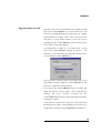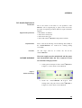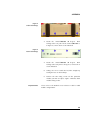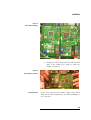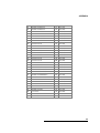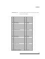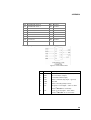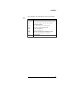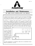
1
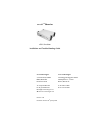
emutelTM|Maestro
xDSL Simulator
Installation and Trouble Shooting Guide
arca technologies
arca technologies
2, Trench Road, Mallusk
Technology Development Center
Belfast, BT36 4TY
Northern Ireland
545 Boylston St., 3rd Floor
Boston, MA 02116
T: +44 (0) 28 9084 5700
T: 001 800 375 9925
F: +44 (0) 28 9084 5701
F: 001 617 262 9484
E: [email protected]
W: www.arca-technologies.com
Revision: 2.3b
Document released: 26th January 2005
TABLE OF CONTENTS
Table of Contents
Introduction
………….Page 3
Product Specification
………….Page 4
Installation
………….Page 6
Configuration Software
………….Page 8
Fault Finding
………..Page 16
Quick Reference Guide
………..Page 19
Appendices:
Uploading Maestro Code
………..Page 20
Upgrading ATM Code
………..Page 22
Upgrading Website Code
………..Page 23
Module Replacement
………..Page 24
Telebyte Tab
………..Page 28
Pin Outs
………..Page 30
LEDs
………..Page 35
Glossary
………Page 36
INTRODUCTION
The emutelTM|Maestro
Thank you for choosing emutelTM|Maestro, a powerful tool for
developers,
manufacturers
and
resellers
of
xDSL
products.
emutelTM|Maestro replaces the requirement for an xDSL (ADSL,
SHDSL or VDSL) line from a Central Office DSLAM.
emutelTM|Maestro is available with several different manufacturer
Central Office interfaces and connection to an external baseband
telephone system via the LINE interface.
emutelTM|Maestro allows ADSL and POTS/ISDN terminals to be
connected simultaneously, via an external splitter, to allow full
interoperability testing and demonstration.
The POTS and ISDN interfaces can be provided by an external
POTS\IDSN (U interface) device connected via an external splitter to
the LINE# ports. There are no user serviceable parts inside
emutelTM|Maestro. The unit should only be opened by approved
maintenance staff; otherwise the warranty will be invalidated.
3
PRODUCT SPECIFICATION
xDSL Connections
The emutelTM|Maestro xDSL Central Office (CO) interfaces can
be configured to operate in various modes, however these may
change depending on the chipset currently fitted within the unit.
Multimode operates by choosing the best mode for operation
with the connected Customer Premise Equipment (CPE). Other
operational parameters and data can be altered or read with the
Configuration Software.
The CPE can be connected directly to the interface or through a
splitter if POTS/ISDN terminal equipment is to be connected
simultaneously.
LED’s indicate the operating status of each interface. For
example, LED1 indicates configuration parameters have been
accepted and the chipset is attempting to make a DSL
connection. LED2 indicates ‘Showtime’ has been achieved
between the module and the external modem equipment. LED 5
and 6 indicate traffic passing through the Maestro. They can be
made to operate for either any data being received/transmitted
over the xDSL ports or just for configured channels.
LED 5
indicates data being received and LED 6 indicates data being
transmitted. LEDs 3 & 4 will be used for future development.
The LINE LED refers to the unit being configured to accept an
external baseband telephone system via the LINE port (POTS or
ISDN).
LINE Connections
The emutelTM|Maestro provides the option for either 1 Plain Old
Telephone System (POTS) or 1 ISDN connection and 1 ADSL
simulation concurrently on the same CO port.
POTS/ISDN equipment can be connected directly to the CO
interface or through a splitter if ADSL terminal equipment is to
be connected simultaneously.
UTOPIA Connections
The emutelTM|Maestro provides a Level 2 Direct Status Indication
UTOPIA interface. The PHY addresses are configurable using the
Configuration Software. These connections allow direct access to
the ATM data stream in and out of each xDSL CO port.
Terminal Port
A V.24 port is provided allowing the connection of the
4
PRODUCT SPECIFICATION
Configuration Software via PC with a serial port.
Ethernet Port
An IEEE 802.3 Ethernet port is provided for connection to the
Configuration Software using a local area network running
TCP/IP protocol.
LEDs indicate (1) network present, (2) network activity.
5
INSTALLATION
Unpack the emutelTM|Maestro
First unpack the emutelTM|Maestro and check for signs of damage in
transit. If the unit or packaging is damaged this should be reported
immediately to arca technologies.
Take an Inventory
Take an inventory of the parts supplied. Check that the items
ordered were actually received. The list below should be of help in
identifying each part.
Connect to a PC or terminal
§
emutelTM|Maestro –
§
Cable for serial connection- RS232
§
2 off RJ11 Modem Leads
§
Mains Cable
§
This Manual
§
Configuration Software CDROM
Plug the serial cable into the Terminal port at the rear of the unit
and connect to a PC. (emutelTM|Maestro default terminal settings
are 19200 baud, 8 data bits, no parity, 1 stop bits.)
Power
The emutelTM|Maestro will operate on a mains voltage of 110-240V
a.c. (50-60Hz).
Connect power
Plug the power cable into the rear of the unit and power on using
the switch located on the mains inlet. Power should be supplied via
an IEC mains lead (supplied).
Warning: The power supply must have a protective ground (earth).
If not, the mains filter will force the metal case to a voltage equal
to half the mains supply voltage.
Configure emutelTM|Maestro
Install the Configuration Software from the CDROM provided (refer
to Configuration Software section). From the Comms menu select
Connect. A pop-up screen will appear showing the progress as the
Configuration Software reads the unit’s configuration data. The unit
should have the factory default settings, but to be certain reset the
unit using the Reset command in the System menu. During this
procedure there will be two pop-up screens, the first indicating a
Reset command and the second showing the new settings being
read from the unit.
CHAPTER 1
6
INSTALLATION
Connecting Terminal Equipment
The connections on xDSL CO1 and xDSL CO2 allow the user four
possible connection scenarios:
§
Direct connection of xDSL CPE
§
Combined connection of ADSL CPE and POTS Equipment
using a Splitter (Annex A)
§
Combined connection of ADSL CPE and ISDN Terminal
Equipment using a Splitter (Annex B)
§
Connection of an external baseband POTS\ISDN telephone
system with external splitter.
N.B. Make sure that the equipment is compatible with the interface
it is connected to.
Connecting an External Baseband Analogue
If you require the use of an external POTS system, , connect the
Telephone System
external POTS system to the corresponding Line port via an external
POTS splitter.
Connecting an External Baseband ISDN
If you require the use of an external ISDN system,, connect the
Telephone System
external ISDN system to the corresponding Line port via an external
ISDN splitter.
Connecting UTOPIA Equipment
If you require connection to the UTOPIA bus then two 80 way High
Density connectors should be used. The connections are shown in
the Appendix. Go to the System menu option and select xDSL>Utopia. All data will be directed to the Utopia ports at the back of
the unit
CHAPTER 1
7
CONFIGURATION SOFTWARE
Installing the Configuration Software
1 Insert the emutelTM|Maestro Software CD into the CD drive of
your machine. If autorun is enabled on your PC then the
installation will begin automatically. Otherwise, read the contents
of the CD via Windows Explorer and double click setup.exe.
2 The following dialog will appear.
Wait until the status bar at the bottom of the dialog has completely
filled.
3 The welcome screen will appear. Click the Next button at the
bottom of the window.
4 The License agreement will appear. Click Yes to accept.
CHAPTER 2
8
CONFIGURATION SOFTWARE
5 The Customer Information Dialog will appear. Enter your name
and your company name into the boxes provided. This
information must be entered before you can proceed. Click on the
Next button to continue the installation.
CHAPTER 2
9
CONFIGURATION SOFTWARE
6 The next dialog that appears will allow you to choose the directory
into which the software will be installed. The default directory is
‘C:\Program Files\Arca Technologies’. Click browse to select a
different directory to install to. Click Next to continue.
7 The Select Program Folder dialog will appear. Click Next to
continue.
8 The installation will then begin as the following dialog appears.
The dialog will disappear when set-up has been completed.
9 Finally, a dialog shall appear to indicate the installation has been
completed.
CHAPTER 2
10
CONFIGURATION SOFTWARE
10 Click Finish to dismiss the dialog.
Running the Configuration Software
From the Start Menu, go to the Programs Directory and select
emutelTM|Maestro Software from the sub-menu. The Software will
then load and the main application window will be displayed.
CHAPTER 2
11
CONFIGURATION SOFTWARE
Connecting via serial port
Ensure that the emutelTM|Maestro is connected to your PC via RS232
connection. Click on the Comms drop-down menu and select
Settings.
The Communications Settings Dialog will appear. Select COM port
as the Port used by clicking the radio button and ensure that the
baud rate, stop bits, parity and data bits are as shown below.
Choose the COM port on your PC that the emutelTM|Maestro is
connected to.
Click OK to confirm these settings. These settings take effect
immediately and will be saved when the Configuration Software is
closed. Therefore it is only necessary to configure the settings once,
and the above steps are not necessary for subsequent connection
attempts.
CHAPTER 2
12
CONFIGURATION SOFTWARE
Finally, go to the Comms drop-down menu and this time select
Connect. Your PC will then attempt to communicate with the
emutelTM|Maestro via the RS232 connection and the configuration
settings will be read from the unit.
The online help describes in detail all of the parameters that can be
configured. Refer to the online help for full descriptions of these
parameters.
Connecting via Ethernet
In order to connect to the emutelTM|Maestro via the LAN interface
you must configure the appropriate IP settings.
In order to change the emutelTM|Maestro IP settings it is necessary to
connect via the RS232 port, as described above.
Once connected, go the System drop-down menu and select Set
Maestro IP.
CHAPTER 2
13
CONFIGURATION SOFTWARE
The emutelTM|Maestro IP address dialog will appear.
The default IP address, submask and gateway settings are as shown.
These can be edited. Clicking OK will update the emutelTM|Maestro
IP settings.
N.B. In order for the settings to take effect it is necessary to switch
the emutelTM|Maestro off then on again.
Go to the Comms Menu and select Disconnect to end the serial
communication between the emutelTM|Maestro and your PC.
With the emutelTM|Maestro’s IP settings fully configured, you must
change the communication settings for the applications to
communicate with the emutelTM|Maestro via the Ethernet port.
Select Settings from the Comms Menu.
CHAPTER 2
14
CONFIGURATION SOFTWARE
The Communications Settings Dialog will appear. Select Ethernet as
the port used by clicking the Ethernet radio button.
Enter the IP address of the emutelTM|Maestro. Clicking OK will
confirm the new configuration settings. These settings will be saved
when the application is terminated.
Finally, go to the Comms drop-down menu and this time select
Connect. Your PC will then attempt to communicate with the
emutelTM|Maestro via the Ethernet connection and the configuration
settings will be read from the unit.
Using the Configuration Software
For further details on using the emutelTM|Maestro software, please
refer to the on-line help file. You can select this from the Emutel
Maestro program group or via the Help menu within the
configuration software.
CHAPTER 2
15
FAULT FINDING
Introduction
This section seeks to provide some guidance on solving common
problems encountered in using emutelTM|Maestro.
Unit does not power up
Check to see if the internal cooling fan is operating. If the fan is
working correctly you should hear a whirring sound.
If the fan is not operational then look at the LEDs and LCD. If
these are also off then check the mains lead is connected properly.
If the mains lead is connected properly then check that the mains
switch on the rear of the emutelTM|Maestro is on. If so then test
your mains supply by plugging in another piece of equipment i.e.
use a table lamp. If the power supply is present then try a new
supply lead.
Showtime does not occur
Assuming the emutelTM|Maestro and CPE are powered on, set the
connection variables to default by following the procedure for a
system reset detailed in the Quick Reference Guide section. If the
CPE does not achieve Showtime after this check that the CPE being
connected is compatible with the chipset installed in the
emutelTM|Maestro. If the CPE still does not achieve Showtime then
try the other port. If this fails try another CPE or another RJ11
lead.
Configuration Software does not connect to the
TM
emutel |Maestro using the LAN port.
In the event that the Configuration Software fails to connect to the
emutelTM|Maestro through the Ethernet port then first check that
the unit is on. If the unit is on then check that the correct leads are
connected to the correct ports; for example, LAN port and not the
10Baset port. If you are connecting your PC directly to the LAN
interface you will require a cross over cable, whereas if you are
connecting via a hub you will require a straight through cable. If
the unit still does not respond then check the connection setup in
the Configuration Software by referring to the online Help. If this
fails try connecting using the serial port. If this fails refer to the
section below.
Configuration Software does not connect to the
TM
emutel |Maestro using Terminal Port
In the event that the Configuration Software fails to connect to the
emutelTM|Maestro using the Terminal port then first check that the
unit is on. If the unit is on then check that the correct leads are
connected to the correct ports. If the unit still does not respond
CHAPTER 3
16
FAULT FINDING
then check the connection setup in the Configuration Software by
referring to the online Help. If this fails execute the Restoring
Default Settings procedure given in the Quick Reference Guide
section.
Unit fails to display status of module
If the LCD does not display the status of a module then the
module has not been recognised by the unit. Try powering the unit
off then wait a few seconds and power it on again. If the LCD
displays “Inactive” beside the CO port, this indicates that the
firmware currently installed is not compatible with the current
module configuration. Refer to the compatibility table in the
appendices.
emutelTM|Maestro fails to respond after a setting
If this occurs the simplest method to recover is to follow the
is changed
Restoring Defaults procedure given in the Quick Reference Guide
section. Settings will only be applied once the “Apply” button has
been selected.
Traffic is not being passed through to the ATM
Check that the appropriate ATM settings have been setup within
port.
the ATM configuration tab. Settings that have been used by Arca
Technologies are as follows:
For connection through to the ATM port:
VPI=8
VCI=80
MPHY=MOD1 or 2
AAL Type=AAL0
Cell Rate=10000
VPI=0
VCI=80
MPHY=ATM
AAL Type=AAL0
Cell Rate=10000
For connection through to the Ethernet port:
VPI=8
VCI=35
MPHY=MOD1 or 2
CHAPTER 3
17
FAULT FINDING
AAL Type=AAL5
Cell Rate=10000
Ensure that the correct ATM connection is being used, Multimode
and Single Mode ATM boards are available.
CHAPTER 3
18
QUICK REFERENCE GUIDE
Restoring default settings
To restore the emutelTM|Maestro to factory defaults you can use
either of two methods.
The first method uses the Configuration Software. Select the
SYSTEM pull down tab and click on the RESET option. A dialog box
will appear instructing you to power cycle the unit. This will reset the
emutelTM|Maestro to the factory default settings and will re-establish
communication with the emutelTM|Maestro.
The second method needs a Communication package such as Hyper
Terminal. The procedure is as follows:
1.
Set the com port to 19200 baud, No parity, 1 Stop bit, 8
Data bits
2.
Hold down <CTRL> and <C> on the keyboard
3.
Switch on the emutelTM|Maestro
4.
Wait until the screen appears with a number of RESET
commands.
When the unit is first switched on the terminal port will search for a
<CTRL-C> being transmitted to the emutelTM|Maestro. If this occurs
the emutelTM|Maestro will restore the factory defaults otherwise it
will use the previously stored settings.
Accessing online Help
Type <F1> at any stage and the help screen shall appear.
CHAPTER 4
19
APPENDIX
Uploading Maestro Code using
the Configuration Software
In order to uploadthe Maestro code the user will first need to start
the Configuration Software.
Please ensure that all cables are disconnected from the unit, except
for the power and serial cables.
Ensure that the emutelTM|Maestro is connected to your PC via the
RS232 connection and that communication has been established
using the Comms pull-down tab and the Connect option – see
section “Connecting via serial port”
Maestro code
Maestro code is for the main part of the emutelTM|Maestro.
Whereby you are required to load the appropriate Maestro code
which matches the module type fitted into the unit. There are seven
versions of Maestro code which are listed within the Appendices
section, “Module Cross Reference table”. To load new Maestro
code, select the SYSTEM pull-down tab followed by the Upload
Maestro Code option.
Either enter the full file name and path or use the Browse button to
select the file for uploading into the emutelTM|Maestro. The default
installation directory is C:\program files\arca technologies\Emutel
maestro Software\Firmware.
20
APPENDIX
Once the file has been selected click on the START button.
In order to start the re-programming process please switch the
emutelTM|Maestro off and back on again.
You should now see the six LEDs of Port 1 on the front of the
emutelTM|Maestro rotating in sequence. You should also see the
Upload Progress bar slowly moving across.
Do not switch the
TM
emutel |Maestro off.
Once the above message appears you should click on the Close
button and switch the emutelTM|Maestro off and back on to
complete the reprogramming.
Re-connect to the emutelTM|Maestro using the Comms pull down
tab and the Connect option.
Now check that the software has been correctly recognised by the
emutelTM|Maestro by using the System pull down tab and the
Configuration option.
Finally perform a System Reset using the System pull down tab and
the Reset option. After waiting for the reset process to finish please
switch the emutelTM|Maestro off and back on.
21
APPENDIX
ATM code is for the ATM board within the emutelTM|Maestro. To
Upgrading ATM Code
load new ATM code select the SYSTEM pull-down tab followed by
the Upload ATM Code option.
As before, either enter the full file name and path or use the Browse
button to select the file for uploading into the emutelTM|Maestro.
Once the file has been selected click on the START button.
You should now see 4 LEDs (1, 2, 4 and 5) of Port 1 on the front of
the emutelTM|Maestro rotating in sequence. You should also see the
Upload Progress bar slowly moving across.
Do not switch the
TM
emutel |Maestro off.
Once the above message appears you should click on the
Close button and then switch the emutelTM|Maestro off and
back on to complete the reprogramming.
Re-connect to the emutelTM|Maestro using the Comms pull
down tab and the Connect option.
Now check that the software has been correctly recognised
by the emutelTM|Maestro by using the System pull down tab
and the Configuration option.
Finally perform a System Reset using the System pull down
tab and the Reset option. After waiting for the reset process
to finish please switch the emutelTM|Maestro off and back on.
22
APPENDIX
Upgrading Web-site code
Web Site code is for the Internal Web Server within the ATM
part of the emutelTM|Maestro. To load new Web Site code
select the SYSTEM pull-down tab followed by the Upload
Internal Web Server option. Either enter the full file name
and path or use the Browse button to select the file for
uploading into the emutelTM|Maestro. Once the file has been
selected click on the START button.
You should now see 4 LEDs (2, 3, 5 and 6) of Port 1 on the
front of the emutelTM|Maestro rotating in sequence.
You
should also see the Upload Progress bar slowly moving across.
Do not switch the emutelTM|Maestro off.
Once the above message appears you should click on the
Close button and then switch the emutelTM|Maestro off and
back on to complete the reprogramming.
Re-connect to the emutelTM|Maestro using the Comms pull
down tab and the Connect option.
software
has
been
correctly
Now check that the
recognised
by
the
emutel |Maestro by using the System pull down tab and the
TM
Configuration option.
Finally perform a System Reset using the System pull down
tab and the Reset option. After waiting for the reset process
to finish please switch the emutelTM|Maestro off and back on.
23
APPENDIX
DSL Module Replacement
Introduction
Equipment Requirements
Due to the nature of the APIs it is not possible to have
Maestro code to support plug ‘n’ play. For this reason the
procedure for replacing a module shall also require a firmware
upgrade.
1 off Pozidrive screwdriver
1 off RS-232 9-9 way lead
1 off Electric Power lead
1 off PC with emutelTM|Maestro Configuration Software
Important Note
Please ensure that all fixings removed during disassembly of
the emutelTM|Maestro are retained for refitting during
reassembly!
Procedure
The first stage shall be to remove the lid off the
emutelTM|Maestro.
HAZARD WARNING
The mains supply must be switched off and the power
lead disconnected before the lid is removed as there
are hazardous voltages present!
1. Looking at the front panel of the emutelTM|Maestro as
in Figure 1, remove the 5 screws indicated.
Figure 1
Front Panel Fixings
2. Rotate the emutelTM|Maestro 90 degrees. Now
looking at the side panel of the emutelTM|Maestro as
in Figure 2, remove the 4 screws indicated.
24
APPENDIX
Figure 2
Side Panel Fixings
3. Rotate the emutelTM|Maestro 90 degrees. Now
looking at the rear panel of the emutelTM|Maestro as
in Figure 3, remove the 4 screws indicated.
Figure 3
Rear Panel Fixings
4. Rotate the emutelTM|Maestro 90 degrees. Now
looking at the side panel as in Figure 2, remove the 4
screws indicated.
5. Taking care not to scratch the lid, lift it straight up
leaving the base on the worktop.
6. Remove the two fixing screws off the particular
module you wish to replace. Figure 4 indicates both
modules fixing screws.
Important Note
Please refer to the Modules cross Reference Table for valid
module configurations.
25
APPENDIX
Figure 4
DSL Module Fixings
7. Placing your fingers firmly under the back and front
edges of the module prise gently to extract the
module. See Figure 5.
Figure 5
DSL Module Removal
Important Note
Please ensure that when the module is being extracted that
both ends are lifted simultaneously. This will avoid damage to
the connectors!
26
APPENDIX
8. Place the new module in exactly the same position
taking care to align the connectors. Press the module
firmly above each connector to feel the positive fit of
the connectors. It may be necessary to place finger
below the motherboard for support and to ensure a
good contact.
9. Inspect the connections to ensure they are correctly
seated.
10. Refit the two fixing screws back into place as in
Figure 4.
11. Replace the lid taking care to align the feet on the
base correctly.
12. Refit one screw on each of the sides of the enclosure.
13. Reconnect the electric power lead.
14. Connect the Maestro to a PC using the RS-232 lead
15. Upload the Maestro code supplied for the DSL
module’ using the Configuration Software.
16. Power off the emutelTM|Maestro.
17. Power on the emutelTM|Maestro taking note of the
module description on the front panel display.
18. If the module has been identified correctly and goes
into TRAINING then the uploadwas successful and
the remaining screws should be fitted to the
enclosure.
19. Place the old module into the protective packaging
that the new module was supplied in.
27
APPENDIX
Telebyte 458-2SL 2-port Line
Simulator The emutelTM|Maestro is capable of controlling the 2-port Line
Simulator from Telebyte, Inc., of Greenlawn, New York –
www.telebyteusa.com . The Telebyte is connected to the
emutelTM|Maestro using a serial lead which means that the
emutelTM|Maestro must be controlled from the Windows Application
using it’s 10Base-T Ethernet port. See the section above marked
Communicating via Ethernet port on how to set this up.
The Telebyte is connected to the emutelTM|Maestro using a MaleMale 9-way ‘D’ serial cable with the following wiring:
Maestro
Telebyte
Pin 1
Pin 6 and Pin 8
Pin 2
Pin 3
Pin 3
Pin 2
Pin 5
Pin 5
The 9-way ‘D’ with the loop between pins 6 & 8 should be
connected to the Telebyte.
Power-on sequence • Power on the Telebyte
•
•
•
•
Connect using the above serial cable
Connect the emutelTM|Maestro to the PC using an Ethernet cable
Power on the emutelTM|Maestro
Start the Windows Application on the PC and ‘Connect’ to the
emutelTM|Maestro using Ethernet
If the two units are already connected then power on the Telebyte,
wait until its display shows the current distance configurations of the
line cards and then power on the emutelTM|Maestro. This sequence
allows the emutelTM|Maestro to check for the presence of the
Telebyte at power on. If the emutelTM|Maestro is powered on first it
will not detect the Telebyte when it is switched on.
If you wish to remove the connection to the Telebyte and
communicate with the emutelTM|Maestro using the serial lead it is
necessary to power-down the emutelTM|Maestro, connect the
emutelTM|Maestro to the PC using the supplied serial lead and then
power-on the emutelTM|Maestro. The emutelTM|Maestro determines
its configuration of the serial port for communication with the
Telebyte or PC only at power-on.
Whenever the Windows Application is started and communications
with the emutelTM|Maestro has been established there will be a tab
28
APPENDIX
for the Telebyte if it has been correctly detected. If the tab is not
present then check the connections and repeat the power-on
sequence above.
The above is an example of the Telebyte tab within the Windows
Application. For more information on the operation of the Telebyte
see the relevant section of the Windows Application Help. Not all of
the commands in the Telebyte manual are supported so for
Command Line Interface (CLI) please refer to the CLI manual and
use the commands detailed there.
If the display on the Telebyte and the emutelTM|Maestro do not show
the same information then click on the REFRESH button. This
updates the emutelTM|Maestro with the settings already in the
Telebyte.
After changing any parameters in the Telebyte tab it is necessary to
click on the APPLY button to send the new settings to the Telebyte.
29
APPENDIX
Pin Outs
xDSL CO Pin-out
The following table shows the pin-out of the RJ11 connector
for the ADSL CO interfaces.
RJ11 connector
LINE Pin-out
1
NC
2
TIP
3
TIP
4
RING
5
RING
6
NC
The following table shows the pin-out of the RJ11 connector
for the LINE (external baseband telephone system) interfaces.
RJ11 connector
1
NC
2
NC
3
TIP
4
RING
5
NC
6
NC
6 5 4 3 2 1
Figure 1 RJ11 plug (front view)
30
APPENDIX
The following table shows the pin-out of the RJ45 connector
for the Ethernet interface.
Ethernet interface Pin-out
RJ45 connector
1
T+
2
T-
3
R+
4
NC
5
NC
6
R-
7
NC
8
NC
8 7 6 5 4 3 2 1
Figure 2 RJ45 plug (front view)
UTOPIA TX Pin-out
The following table shows the pin-out of the 80 way High
Density connector UTOPIA.
1
Not Connected
2
Ground
3
Not Connected
4
Ground
5
Not Connected
6
Ground
7
Not Connected
8
Ground
9
Not Connected
10
Ground
11
Not Connected
12
Ground
13
Not Connected
14
Ground
15
Not Connected
16
Ground
17
UTOPIA TX DATA 0
18
Ground
19
UTOPIA TX DATA 1
20
Ground
31
APPENDIX
21
UTOPIA TX DATA 2
22
Ground
23
UTOPIA TX DATA 3
24
Ground
25
UTOPIA TX DATA 4
26
Ground
27
UTOPIA TX DATA 5
28
Ground
29
UTOPIA TX DATA 6
30
Ground
31
UTOPIA TX DATA 7
32
Ground
33
Not Connected
34
Ground
35
Not Connected
36
Ground
37
Not Connected
38
Ground
39
Not Connected
40
Ground
41
Not Connected
42
Ground
43
Not Connected
44
Ground
45
Not Connected
46
Ground
47
Not Connected
48
Ground
49
Not Connected
50
Ground
51
UTOPIA TX SOC
52
Ground
53
UTOPIA TX ENB
54
Ground
55
UTOPIA TX ADDRESS 0
56
Ground
57
UTOPIA TX ADDRESS 1
58
Ground
59
UTOPIA TX ADDRESS 2
60
Ground
61
UTOPIA TX ADDRESS 3
62
Ground
63
UTOPIA TX ADDRESS 4
64
Ground
65
UTOPIA TX CLAV 0
66
Ground
67
UTOPIA TX CLAV 1
68
Ground
69
UTOPIA TX CLAV 2
70
Ground
71
UTOPIA TX CLAV 3
72
Ground
73
UTOPIA TX CLK
74
Ground
75
Do not use
76
Ground
77
Do not use
78
Ground
79
Do not use
80
Ground
32
APPENDIX
UTOPIA RX Pin-out
The following table shows the pin-out of the 80 way High
Density connector UTOPIA.
1
Not Connected
2
Ground
3
Not Connected
4
Ground
5
Not Connected
6
Ground
7
Not Connected
8
Ground
9
Not Connected
10
Ground
11
Not Connected
12
Ground
13
Not Connected
14
Ground
15
Not Connected
16
Ground
17
UTOPIA RX DATA 0
18
Ground
19
UTOPIA RX DATA 1
20
Ground
21
UTOPIA RX DATA 2
22
Ground
23
UTOPIA RX DATA 3
24
Ground
25
UTOPIA RX DATA 4
26
Ground
27
UTOPIA RX DATA 5
28
Ground
29
UTOPIA RX DATA 6
30
Ground
31
UTOPIA RX DATA 7
32
Ground
33
Not Connected
34
Ground
35
Not Connected
36
Ground
37
Not Connected
38
Ground
39
Not Connected
40
Ground
41
Not Connected
42
Ground
43
Not Connected
44
Ground
45
Not Connected
46
Ground
47
Not Connected
48
Ground
49
Not Connected
50
Ground
51
UTOPIA RX SOC
52
Ground
53
UTOPIA RX ENB
54
Ground
55
UTOPIA RX ADDRESS 0
56
Ground
57
UTOPIA RX ADDRESS 1
58
Ground
59
UTOPIA RX ADDRESS 2
60
Ground
61
UTOPIA RX ADDRESS 3
62
Ground
63
UTOPIA RX ADDRESS 4
64
Ground
33
APPENDIX
65
UTOPIA RX CLAV 0
66
Ground
67
UTOPIA RX CLAV 1
68
Ground
69
UTOPIA RX CLAV 2
70
Ground
71
UTOPIA RX CLAV 3
72
Ground
73
UTOPIA RX CLK
74
Ground
75
Do not use
76
Ground
77
Do not use
78
Ground
79
Do not use
80
Ground
Terminal port pin-out
Figure 3 V.24 Terminal Port
Pin
Function
Description
1
2
3
DCD
RXD
TXD
Data Carrier Detect (always active)
Received Data (output)
Transmitted Data (input)
4
5
DTR
GND
Data Terminal Ready (input - ignored)
Ground
6
7
DSR
RTS
Data Set Ready (always active)
Request to Send (input - active to allow
emutelTM|Maestro to send Data)
8
CTS
Clear to Send (output - active when
emutelTM|Maestro can receive Data)
34
APPENDIX
LEDs
This a description of the LED indicators on the front and back
panels
LED
LINE
Description
This port is used to connect to the external
POTS\ISDN network
LED1
LED2
LED3
LED4
LED5
The xDSL module has been detected
The port is in the showtime state
Future development
Future Development
Indicates data being transmitted from xDSL
LED6
Indicates data being received by xDSL
A
System Alarm
¼
Power On
35
GLOSSARY
Definitions
AAL0
AAL5
ADSL
ANSI
ATM
ATU-C
ATU-R
BER
BRI
CO
CPE
DSL
DSLAM
FTP
HTML
IP
ISDN
LAN
LCD
PC
POTS
PSTN
SHDSL
VCI
VDSL
VPI
ATM Adaption Layer 0
ATM Adaption Layer 5
Asymmetric Digital Subscriber Line
American National Standards Institute
Asynchronous Transfer Mode
ADSL Transceiver Unit – Central Office
ADSL Transceiver Unit – Remote
Bit Error Rate
Basic Rate Interface
Central Office
Customer Premise Equipment
Digital Subscriber Line
Digital Subscriber Line Access Multiplexer
File Transfer Protocol
HyperText Markup Language
Internet Protocol
Integrated Services Digital Network
Local Area Network
Liquid Crystal Display
Personal Computer
Plain Old Telephone Service over PSTN
Public Switched Telephone Network
Symmetric High speed DSL
Virtual Channel Identifier
Very high speed DSL
Virtual Path Identifier
36