Download IP / ANALOG SURVEILLANCE CAMERA Quick Installation Guide
Transcript
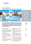
IP / ANALOG SURVEILLANCE CAMERA DN-16050 / DN-16051/DN-16052/DN-16052 Quick Installation Guide 1. HARDWARE OVERVIEW 1.1 Rear Panel CONNECTOR / BUTTON DESCRIPTION Reset Default This button is hidden in the pinhole. Press and hold the reset button until the network camera rebooted. This will reset all parameters, including the IP address to factory default settings. Power Indicator When the camera is power-supplied, this indicator will be on as red. Audio Output (DN-16051/DN-16052/DN-16052 only) Support the connection to an audio device, such as a speaker, for voice transmission of the remote side. Audio Input (DN-16051/DN-16052/DN-16052 only) Support the connection to an audio device, such as a microphone, for voice transmission of the local side. Video Output Connect to the video input connector of your monitor with a video cable (i.e. a RCA line with the BNC connector, or a coaxial line) for video output. * The video cable is optional. LAN Connect the camera to the network with the supplied RJ45 cable. Power Connector Connect the DC 12V adapter for power supply. Alarm Connector (DN-16051/DN-16052/DN-16052 only) Support the connection to an alarm device for function scalability. 1.2 Upper Side & Underside 1.3 Package Contents □ □ □ □ Network camera Adapter and power cord Bracket RJ45 network cable □ Quick user guide □ CD-ROM disc for user manual □ CD-ROM disc for Video Viewer AP Software INSTALLATION 2. INSTALLATION 2.1 Install the Hardware This camera can be installed in two ways: ceiling-mounted and desktop. During the installation, please make sure the upper side of the camera is always facing up, as shown in Figure 1 below, regardless of which installation way you’re using. This is to ensure the video output won’t be up side down. Note: The illustrations below are based on the ceiling-mounted installation. Note: For the detailed cable connection, please refer to the section “Rear Panel”. Tool needed: Power drill x 1 (not supplied within the sales package) 1. Prepare all the parts needed for camera installation. Find the network camera, bracket package, a bag of screws & wall plugs, and a cap supplied with the sales package, as shown in Figure 1. Unpack the bracket package to find the bracket disassembled into three parts: the base, stem and joint lock. Figure 1: Parts needed for camera installation 2. Fix the base of the bracket. Fix the base of the bracket with the supplied 3 screws to the place you want to install by using a power drill. Figure 2: Screw the base to the ceiling 3. Assemble the bracket: a). Align the stem with the central hole of the base, and rotate it to secure, as shown in Figure 3. b). Align the joint lock with the stem, and rotate it to secure, as shown in Figure 4. Figure 3: Connect the stem to the base Figure 4: Connect the joint lock to the stem 4. Connect the camera to the bracket. Ceiling-mounted: With the upper side of the camera facing up, align the mounting screw hole on the upper side with the screw thread of the joint lock, and rotate the camera to secure, as shown in Figure 4. Desktop: With the upper side of the camera facing up, align the mounting screw hole on the underside with the screw thread of the joint lock, and rotate the camera to secure. Figure 4: Connect the camera to the bracket 5. Insert the cap to the other mounting screw hole of the camera. Ceiling-mounted: Insert the cap to the mounting screw hole on the underside of the camera, as shown in Figure 5. Desktop: Insert the cap to the mounting screw hole on the upper side of the camera. 6. Adjust the viewing angle of the camera, and fasten the joint lock to fix the angle. The installation is completed, as shown in Figure 6. Figure 5: Insert the cap to the camera Figure 6: Finish the installation 3.2 Assign an IP address and Access the Camera Step 1. Install the Software Place the supplied Video Viewer AP software CD into your DVD- / CD-ROM drive. The installation process will automatically start. Follow the on-screen instructions to install the application programs. After installation, a “Video Viewer” shortcut icon will be shown on your PC desktop. Step 2. Connect the network camera to the Internet access via a RJ-45 network cable. Step 3. Search the available IP address to login a) Double-click “ Book” ( b) ” icon on your PC desktop to enter the Video Viewer control panel. By defaults, the “Address ) panel will be displayed on the right side of the Video Viewer control panel. Click ” ” (Search) ” ” (Refresh) to search the available IP address(es). The found address(es) will be listed, and can be added into the address book by clicking ” For details, please see “ ” (Add into address book). ” (Search) in the user manual. c) Select the IP address you just added into the address book, and click “ d) Double-click the IP address in the address book to login. ” (Edit) to edit the settings. Note: For detailed network settings under different network types (Static IP / PPPOE / DHCP), please refer to “Network” and “DDNS” in the user manual. ‧ If you cannot search any available IP address, please follow the instructions below. Step 4. Add the IP address and other network settings to login a) Double-click “ ” icon on your PC desktop to enter the Video Viewer control panel. By defaults, the “Address Book” panel will be displayed on the right side of the Video Viewer control panel. b) c) The default network camera settings are as follows: Item Default Setting IP Address 192.168.1.10 User Name admin Password admin Port Number 80 Click ” ” (Address Book) ” ” (Add) button to key in the IP address, user name, password, and port number of the network camera you intend to connect. d) Item Default Setting IP Address 192.168.1.10 User Name admin Password admin Port Number 80 Double-click the IP address you just added into the address book to login.


