1
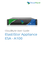
CloudByte User Guide
ElastiStor Appliance
ESA - A100
The information in this User’s Manual has been carefully reviewed and is believed to be accurate.
The vendor assumes no responsibility for any inaccuracies that may be contained in this document,
makes no commitment to update or to keep current the information in this manual, or to notify any
person or organization of the updates. Please Note: For the most up-to-date version of this
manual, please see our web site at www.cloudbyte.com.
CloudByte, Inc. ("CloudByte") reserves the right to make changes to the product described in this
manual at any time and without notice. This product, including software and documentation, is the
property of CloudByte and/or its licensors, and is supplied only under a license. Any use or reproduction of this product is not allowed, except as expressly permitted by the terms of said license.
IN NO EVENT WILL CLOUDBYTE BE LIABLE FOR DIRECT, INDIRECT, SPECIAL, INCIDENTAL,
SPECULATIVE OR CONSEQUENTIAL DAMAGES ARISING FROM THE USE OR INABILITY TO
USE THIS PRODUCT OR DOCUMENTATION, EVEN IF ADVISED OF THE POSSIBILITY OF SUCH
DAMAGES. IN PARTICULAR, CLOUDBYTE SHALL NOT HAVE LIABILITY FOR ANY HARDWARE,
SOFTWARE, OR DATA STORED OR USED WITH THE PRODUCT, INCLUDING THE COSTS OF
REPAIRING, REPLACING, INTEGRATING, INSTALLING OR RECOVERING SUCH HARDWARE,
SOFTWARE, OR DATA.
Unless you request and receive written permission from CloudByte, Inc., you may not copy any
part of this document.
Information in this document is subject to change without notice. Other products and companies
referred to herein are trademarks or registered trademarks of their respective companies or mark
holders.
Copyright © 2014 by CloudByte, Inc.
All rights reserved.
Preface
Preface
About This Manual
This manual is written for professional system integrators and PC technicians.
It provides information for the installation and use of the CloudByte ElastiStor
Appliance-A100 (ESA-A100). Installation and maintenance should be performed
by experienced technicians only.
The ESA-A100 is a high-end storage server solution based on the rackmount chassis and the dual processor serverboard.
Manual Organization
Chapter 1: Introduction
The first chapter provides a checklist of the main components included with the
server system and describes the main features of the serverboard and the chassis.
Chapter 2: Server Installation
This chapter describes the steps necessary to install the ESA-A100 into a rack and
check out the server configuration prior to powering up the system. If your server
was ordered without processor and memory components, this chapter will refer you
to the appropriate sections of the manual for their installation.
Chapter 3: System Interface
Refer here for details on the system interface, which includes the functions and
information provided by the control panels on the chassis as well the HDD carrier
LEDs.
Chapter 4: Standardized Warning Statements
You should thoroughly familiarize yourself with this chapter for a general overview of
safety precautions that should be followed when installing and servicing ESA-A100.
iii
CloudByte ESA-A100 User's Manual
Chapter 5: Advanced Serverboard Setup
Chapter 5 provides detailed information on the serverboard, including the locations and functions of connections, headers and jumpers. Refer to this chapter
when adding or removing processors or main memory and when reconfiguring the
serverboard.
Chapter 6: BIOS
The BIOS chapter includes an introduction to BIOS and provides detailed information on running the CMOS Setup Utility.
Appendix A: BIOS Error Beep Codes
Appendix B: System Specifications
iv
Preface
Notes
v
CloudByte ESA-A100 User's Manual
Table of Contents
Appendix A
BIOS Error Beep Codes
Appendix B
System Specifications
Chapter 1
Introduction
1-1Overview.......................................................................................................... 1-1
1-2
Serverboard Features...................................................................................... 1-2
Processors....................................................................................................... 1-2
Memory............................................................................................................ 1-2
SAS Disk Controller......................................................................................... 1-2
SAS Expander.................................................................................................. 1-2
SATA ............................................................................................................... 1-2
NTB Connectivity............................................................................................. 1-2
PCI Expansion Slots........................................................................................ 1-2
Rear Chassis Ports.......................................................................................... 1-3
Graphics Controller.......................................................................................... 1-3
1-3
Server Chassis Features................................................................................. 1-3
System Power.................................................................................................. 1-3
SAS Subsystem............................................................................................... 1-3
Front Control Panel.......................................................................................... 1-3
Cooling System................................................................................................ 1-3
1-4
Contacting CloudByte...................................................................................... 1-5
1-5
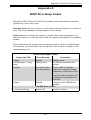
SBB: Storage Bridge Bay................................................................................ 1-6
Chapter 2
Server Installation
2-1Overview.......................................................................................................... 2-1
2-2
2-3
Unpacking the System..................................................................................... 2-1
Preparing for Setup.......................................................................................... 2-1
Choosing a Setup Location.............................................................................. 2-1
2-4
Warnings and Precautions............................................................................... 2-2
Rack Precautions............................................................................................. 2-2
Server Precautions........................................................................................... 2-2
Rack Mounting Considerations........................................................................ 2-3
vi
Table of Contents
Ambient Operating Temperature................................................................. 2-3
Reduced Airflow.......................................................................................... 2-3
Mechanical Loading.................................................................................... 2-3
Circuit Overloading...................................................................................... 2-3
Reliable Ground.......................................................................................... 2-3
2-5
Installing the System into a Rack.................................................................... 2-4
Installing the Inner Rack Rails......................................................................... 2-4
Installing the Outer Rack Rails........................................................................ 2-5
Installing the Chassis into a Rack................................................................... 2-6
Chapter 3
System Interface
3-1Overview.......................................................................................................... 3-1
3-2
Control Panel Button........................................................................................ 3-1
Power............................................................................................................... 3-1
3-3
Control Panel LEDs......................................................................................... 3-1
Power Fail........................................................................................................ 3-1
Overheat/Fan Fail:........................................................................................... 3-2
NIC1................................................................................................................. 3-2
NIC2................................................................................................................. 3-2
Heartbeat.......................................................................................................... 3-2
Power............................................................................................................... 3-3
3-4
Drive Carrier LEDs........................................................................................... 3-3
Chapter 4
Standardized Warning Statements for AC Systems
4-1
About Standardized Warning Statements........................................................ 4-1
Warning Definition............................................................................................ 4-1
Installation Instructions..................................................................................... 4-2
Circuit Breaker................................................................................................. 4-2
Power Disconnection Warning......................................................................... 4-2
Equipment Installation...................................................................................... 4-2
Restricted Area................................................................................................. 4-2
Battery Handling............................................................................................... 4-3
Redundant Power Supplies............................................................................. 4-4
Backplane Voltage........................................................................................... 4-4
Comply with Local and National Electrical Codes........................................... 4-4
Product Disposal.............................................................................................. 4-4
Hot Swap Fan Warning.................................................................................... 4-4
Power Cable and AC Adapter ......................................................................... 4-4
vii
CloudByte ESA-A100 User's Manual
Chapter 5
Advanced Serverboard Setup
5-1
Handling the Serverboard................................................................................ 5-1
Precautions...................................................................................................... 5-1
5-2
Cable and Device Connections....................................................................... 5-2
Power Connections..................................................................................... 5-2
Fan Cabling................................................................................................. 5-2
Control Panels............................................................................................. 5-2
5-3
Installing the Processor and Heatsink............................................................. 5-3
Installing an LGA 1356 Processor................................................................... 5-3
Installing a CPU Heatsink................................................................................ 5-5
Chapter 6
BIOS
6-1 Introduction....................................................................................................... 6-1
Starting BIOS Setup Utility............................................................................... 6-1
6-2 IPMI.................................................................................................................. 6-2
6-3 Boot..................................................................................................................6-4
6-4Security............................................................................................................6-5
6-5
Save & Exit......................................................................................................6-5
viii
Appendix A: BIOS Error Beep Codes
Appendix A
BIOS Error Beep Codes
During the POST (Power-On Self-Test) routines, which are performed at each
system boot, errors may occur.
Non-fatal errors are those which, in most cases, allow the system to continue to
boot. The error messages normally appear on the screen.
Fatal errors will not allow the system to continue with bootup procedure. If a
fatal error occurs, you should consult with your system manufacturer for possible
repairs.
These fatal errors are usually communicated through a series of audible beeps.
The numbers on the fatal error list correspond to the number of beeps for the
corresponding error.
BIOS Error Beep Codes
Beep Code/LED
Error Message
Description
1 beep
Refresh
Ready to boot
5 short beeps + 1 long
beep
Memory error
No memory detected in the
system
5 beeps
No Con-In or No
Con-Out devices
Con-In: USB or PS/2 keyboard, PCI or Serial Console
Redirection, IPMI KVM or SOL
Con-Out: Video Controller, PCI
or Serial Console Redirection,
IPMI SOL
1 beep
Refresh
1 beep for each USB device
installed
X9 IPMI Error Codes
1 Continuous Beep
System OH
A-1
System Overheat
CloudByte ESA-A100 User's Manual
Notes
A-2
Appendix B: System Specifications
Appendix B
System Specifications
Processors (each node)
Single or dual Intel® Xeon E5-2400 of up to 95W in B2 type sockets (both CPUs
must be of the same type)
Note: Please refer to our web site for a complete listing of supported processors.
Chipset
Intel C602J
BIOS
16 Mb AMI® Flash ROM
Memory Capacity (each node)
Six DIMM slots that can support up to 192 GB of Registered (RDIMM) ECC/NonECC DDR3-1866/1600/1333/1066/800 memory
Note: see Section 5-6 for details.
SAS/SATA (each node)
Two external SAS 2.0 x4 ports (eight 6Gb/s lanes) and two SATA 3.0 ports with
power header for for SATA DOM
Drive Bays
Twenty-four hot-swap drive bays to house 3.5" hard drives
Expansion Slots (each node)
Riser card with four PCI-E 3.0 x8 (in x24 slots)
Serverboard (two per system)
X9DBS-F (Proprietary form factor)
Dimensions: 16.64 x 8.1 in (423 x 206 mm)
B-1
CloudByte ESA-A100 User's Manual
Chassis
SC927ETS-R1200NDBP (2U rackmount)
Dimensions: (WxHxD) 17.2 x 3.5 x 26.75 in. (437 x 88 x 679 mm)
Weight (Net): 56 lbs. (25.5 kg.)
Weight
Gross (Bare Bone): 85 lbs. (38.6 kg.)
System Cooling
Three sets of 4-cm counter-rotating fans above each node, two sets of counterrotating fans at the back of each node, one set of counter-rotating fans on each
serverboard (each set contains two fans placed back-to-back)
System Input Requirements
AC Input Voltage: 100 - 240V AC auto-range
Rated Input Current: 11 - 4.5A max
Rated Input Frequency: 50 to 60 Hz
Power Supply
Rated Output Power: 920W (Part# PWS-920P-SQ) 80 Plus Platinum Certified
Rated Output Voltages: +5V (45A), 3.3V (24A), -12V (0.6A)
Operating Environment
Operating Temperature: 10º to 35º C (50º to 95º F)
Non-operating Temperature: -40º to 70º C (-40º to 158º F)
Operating Relative Humidity: 8% to 90% (non-condensing)
Non-operating Relative Humidity: 5 to 95% (non-condensing)
B-2
Appendix B: System Specifications
Regulatory Compliance
Electromagnetic Emissions: FCC Class A, EN 55022 Class A, EN 61000-3-2/-3-3,
CISPR 22 Class A
Electromagnetic Immunity: EN 55024/CISPR 24, (EN 61000-4-2, EN 61000-4-3,
EN 61000-4-4, EN 61000-4-5, EN 61000-4-6, EN 61000-4-8, EN 61000-4-11)
Safety: CSA/EN/IEC/UL 60950-1 Compliant, UL or CSA Listed (USA and
Canada), CE Marking (Europe)
California Best Management Practices Regulations for Perchlorate Materials:
This Perchlorate warning applies only to products containing CR (Manganese
Dioxide) Lithium coin cells. “Perchlorate Material-special handling may apply. See
www.dtsc.ca.gov/hazardouswaste/perchlorate”
B-3
CloudByte ESA-A100 User's Manual
(continued from front)
The products sold by CloudByte are not intended for and will not be used in life support systems,
medical equipment, nuclear facilities or systems, aircraft, aircraft devices, aircraft/emergency communication devices or other critical systems whose failure to perform be reasonably expected to
result in significant injury or loss of life or catastrophic property damage. Accordingly, CloudByte disclaims any and all liability, and should buyer use or sell such products for use in such ultra-hazardous
applications, it does so entirely at its own risk. Furthermore, buyer agrees to fully indemnify, defend
and hold CloudByte harmless for and against any and all claims, demands, actions, litigation, and
proceedings of any kind arising out of or related to such ultra-hazardous use or sale.
B-4
Chapter 1: Introduction
Chapter 1
Introduction
1-1Overview
The ESA-A100 is a high-end Super Storage Bridge Bay (SBB) system comprised
of two main subsystems: the chassis and two dual processor serverboards. Please
refer to our web site for information on operating systems that have been certified
for use with the system (www.cloudbyte.com).
In addition to the serverboard and chassis, various hardware components have
been included with the ESA-A100, as listed below. Quantities indicate the number
included in the whole system (two nodes).
•Four passive CPU heatsinks
•Ten 4-cm counter-rotating fans
•Two KVM cables
•SAS/SATA Accessories
One SAS midplane
Twenty-four hard drive carriers •Two riser cards for PCI-Express 3.0 expansion cards
•Two SAS controller mezzanine cards (one per node)
•One set of rackmount hardware Note: For your system to work properly, please follow the links below to download all necessary drivers/utilities and the user’s manual for your server.
•CloudByte product manuals: http://www.docs.cloudbyte.com
•If you have any questions, please contact our support team at:
[email protected]
1-1
CloudByte ESA-A100 User's Manual
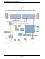
1-2 Serverboard Features
The ESA-A100 is built around two serverboards for a dual-node system that shares
storage resources as well as features a dedicated PCI-E bus between server nodes
for High Availability (HA), Cluster in a Box (CiB) applications The serverboard is
dual processor based on the Intel® C602J chipset. Below are the main features of
the serverboard. (See Figure 1-1 for a block diagram of the chipset).
Processors
The serverboard supports single or dual Intel® Xeon E5-2400 of up to 95W in B2
type sockets. Two serverboards are included in the storage system. Please refer
to the serverboard description pages on our web site for a complete listing of supported processors (www.cloudbyte.com).
Memory
Each X9DBS-F has six DIMM slots that can support up to 192 GB of Registered
(RDIMM) ECC/Non-ECC DDR3-1866/1600/1333/1066/800 memory. See Chapter
5 for details.
SAS Disk Controller
Two external SAS 2.0 ports are supported by a disk controller on a mezzanine
included on each X9DBS-F (four total per system).
SAS Expander
One 36-port SAS expander is integrated into the serverboard.
SATA
Each serverboard has two SATA 3.0 ports with power headers to support two SATA
Disk-on-Module (SATA DOM) devices per node. RAID 0 and 1 are supported.
NTB Connectivity
Non Transparent Bridge connectivity featuring 8 lanes of PCI-E 3.0 between server
nodes.
PCI Expansion Slots
Each X9DBS-F features one PCI-E 3.0 x24 slot for riser/expansion card support.
1-2
Chapter 1: Introduction
Rear Chassis Ports
The rear of each serverboard includes two mini SAS HD ports, two 1 GB Ethernet
ports and a KVM connector (includes USB, VGA and COM ports).
Graphics Controller
The serverboard features an integrated Matrox G200eW video controller. The
G200eW is a 2D/3D/video accelerator chip with a 128-bit core.
1-3 Server Chassis Features
System Power
The ESA-A100 features a redundant Platinum Level 920W power supply composed
of two separate power modules. This power redundancy feature allows you to replace a failed power module without shutting down the system.
SAS Subsystem
The ESA-A100 supports up to 24 3.5" SAS drives. These drives are hot-swappable
units and are connected to a midplane that provides power and control.
Front Control Panel
Two control panels are included on each end of the ESA-A100 to provide you with
system monitoring and control. LEDs indicate system power, network (NIC) activity,
system overheat and power supply failure. Each set of LEDs are associated with the
node/serverboard on the same side of the chassis. A single power button is located
on the right side control panel. When pressed, both nodes will power on or off.
Cooling System
The ESA-A100 chassis has ten 4-cm counter-rotating fans: six at the front and
another four at the rear of each node. This counter-rotating action works to dampen
vibration levels while generating exceptional airflow.
Another set of back-to-back fans are also located on each serverboard in front of
the CPU2 socket. Each power supply module also includes a cooling fan.
1-3
CloudByte ESA-A100 User's Manual
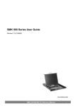
Figure 1-1. Intel C602J Chipset:
System Block Diagram
Note: This is a general block diagram. Please see Chapter 5 for details.
1-4
Chapter 1: Introduction
1-4 Contacting CloudByte
Headquarters
Address:
20863 Stevens Creek Blvd,
Suite 530
Cupertino, CA 95014 USA
Tel:
+1-855-380-BYTE (2983)
Fax:
+1-(408)-663-6900
Email:
[email protected] (General Information)
[email protected] (Technical Support)
Web Site:
www.cloudbyte.com
1-5
CloudByte ESA-A100 User's Manual
1-5 SBB: Storage Bridge Bay
The ESA-A100 Super SBB was designed to function as a fully redundant, faulttolerant "cluster-in-a-box" system. The standard support for 24 3.5" hot-swap HDDs
(SAS1 or SAS2) may be expanded to support additional storage with the optional
SBB JBOD configuration.
The Super SBB provides hot-swappable canisters for all active components. Each
of the two serverboard canisters support dual-processors, 6 DIMM slots, 3 PCI-E
Gen2 slots and 6 Gbps SAS (SAS2). The ESA-A100 features eight lanes of PCI-E
3.0 connecting the left server module with the right server module. This connection
is used for high speed data transfers between nodes for High Availability/server
fail-over. This fail-over capability is fully dependent on the software/OS installed
and how the chosen software uses the connection (Active-Active or Active-Passive).
ESA-A100 hardware is supplied without a storage OS or fail-over software.
Equipped with 920W 80PLUS Platinum Level redundant power supplies and redundant cooling fans, the ESA-A100 offers fully redundant high-availability while
maintaining energy efficient operation.
1-6
Chapter 2: Server Installation
Chapter 2
Server Installation
2-1Overview
This chapter provides a quick setup checklist to get your ESA-A100 up and
running. Following these steps in the order given should enable you to have the
system operational within a minimum amount of time. This quick setup assumes
that your system has come to you with the processors and memory preinstalled. If
your system is not already fully integrated with a serverboard, processors, system
memory etc., please turn to the chapter or section noted in each step for details on
installing specific components.
2-2 Unpacking the System
You should inspect the box the ESA-A100 was shipped in and note if it was damaged in any way. If the server itself shows damage you should file a damage claim
with the carrier who delivered it.
Decide on a suitable location for the rack unit that will hold the ESA-A100. It should
be situated in a clean, dust-free area that is well ventilated. Avoid areas where
heat, electrical noise and electromagnetic fields are generated. You will also need
it placed near a grounded power outlet. Read the Rack and Server Precautions in
the next section.
2-3 Preparing for Setup
The box the ESA-A100 was shipped in should include two sets of rail assemblies,
two rail mounting brackets and the mounting screws you will need to install the
system into the rack. Follow the steps in the order given to complete the installation
process in a minimum amount of time. Please read this section in its entirety before
you begin the installation procedure outlined in the sections that follow.
Choosing a Setup Location
•Leave enough clearance in front of the rack to enable you to open the front door
completely (~25 inches) and approximately 30 inches of clearance in the back
of the rack to allow for sufficient airflow and ease in servicing.
2-1
CloudByte ESA-A100 User's Manual
•This product is for installation only in a Restricted Access Location (dedicated
equipment rooms, service closets and the like).
•This product is not suitable for use with visual display work place devices
acccording to §2 of the the German Ordinance for Work with Visual Display
Units.
2-4 Warnings and Precautions
Rack Precautions
•Ensure that the leveling jacks on the bottom of the rack are fully extended to
the floor with the full weight of the rack resting on them.
•In single rack installation, stabilizers should be attached to the rack. In multiple
rack installations, the racks should be coupled together.
•Always make sure the rack is stable before extending a component from the
rack.
•You should extend only one component at a time - extending two or more simultaneously may cause the rack to become unstable.
Server Precautions
•Review the electrical and general safety precautions in Chapter 4.
•Determine the placement of each component in the rack before you install the
rails.
•Install the heaviest server components on the bottom of the rack first, and then
work up.
•Use a regulating uninterruptible power supply (UPS) to protect the server from
power surges, voltage spikes and to keep your system operating in case of a
power failure.
•Allow any hot plug drives and power supply modules to cool before touching
them.
•Always keep the rack's front door and all panels and components on the servers
closed when not servicing to maintain proper cooling.
2-2
Chapter 2: Server Installation
Rack Mounting Considerations
Ambient Operating Temperature
If installed in a closed or multi-unit rack assembly, the ambient operating temperature of the rack environment may be greater than the ambient temperature of the
room. Therefore, consideration should be given to installing the equipment in an
environment compatible with the manufacturer’s maximum rated ambient temperature (Tmra).
Reduced Airflow
Equipment should be mounted into a rack so that the amount of airflow required
for safe operation is not compromised.
Mechanical Loading
Equipment should be mounted into a rack so that a hazardous condition does not
arise due to uneven mechanical loading.
Circuit Overloading
Consideration should be given to the connection of the equipment to the power
supply circuitry and the effect that any possible overloading of circuits might have
on overcurrent protection and power supply wiring. Appropriate consideration of
equipment nameplate ratings should be used when addressing this concern.
Reliable Ground
A reliable ground must be maintained at all times. To ensure this, the rack itself
should be grounded. Particular attention should be given to power supply connections other than the direct connections to the branch circuit (i.e. the use of power
strips, etc.).
2-3
CloudByte ESA-A100 User's Manual
2-5 Installing the System into a Rack
This section provides information on installing the chassis into a rack unit with the
quick-release rails provided. There are a variety of rack units on the market, which
may mean the assembly procedure will differ slightly. You should also refer to the
installation instructions that came with the rack unit you are using.
Installing the Inner Rack Rails
Installing the Inner Rails
1. Extend the inner rail toward the front of the rail assembly as far as possible,
then depress the locking tab to pull it completely out.
2. Place the inner rail on the side of the chassis aligning the hooks of the chassis with the rail extension holes.
3. Slide the extension toward the front of the chassis.
4. You may secure the chassis with screws if desired.
5. Repeat steps 1-3 for the other inner rail.
12
13
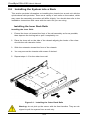
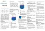
Figure 2-1. Installing the Outer Rack Rails
Warning: do not pick up the server with the front handles. They are designed to pull the system from a rack only.
2-4
Chapter 2: Server Installation
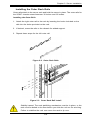
Installing the Outer Rack Rails
Outer rails attach to the server rack and hold the server in place. The outer rails for
the SC937 chassis extend between 30 inches and 33 inches.
Installing the Outer Rails
1. Attach the right outer rail to the rack by inserting the hooks included on the
rails into the holes provided on the rack.
2. If desired, screw the rails to the chassis for added support.
3. Repeat these steps for the left outer rail.
Figure 2-2. Outer Rack Rails
Figure 2-3. Outer Rack Rail Install
Stability hazard. The rack stabilizing mechanism must be in place, or the
rack must be bolted to the floor before you slide the unit out for servicing.
Failure to stabilize the rack can cause the rack to tip over.
2-5
CloudByte ESA-A100 User's Manual
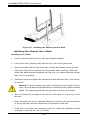
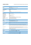
Figure 2-3. Installing the Chassis into the Rack
Installing the Chassis into a Rack
Installing into a Rack
1. Confirm that the inner and outer rails are properly installed.
2. Line up the inner (chassis) rails with the front of the outer (rack) rails.
3. Slide the chassis rails into the rack rails, keeping the pressure even on both
sides (you may have to depress the locking tabs when inserting). When the
server has been pushed completely into the rack, you should hear the locking
tabs "click" into position.
4. (Optional) Insert and tighten the thumbscrews that hold the front of the server
to the rack.
Warning! To prevent bodily injury when mounting or servicing this unit in a
rack, you must take special precautions to ensure that the system remains
stable. The following guidelines are provided to ensure your safety:
•This unit should be mounted at the bottom of the rack if it is the only unit in
the rack.
•When mounting this unit in a partially filled rack, load the rack from the bottom
to the top with the heaviest component at the bottom of the rack.
•If the rack is provided with stabilizing devices, install the stabilizers before
mounting or servicing the unit in the rack.
2-6
Chapter 3: System Interface
Chapter 3
System Interface
3-1Overview
There are several LEDs on two control panels as well as others on the drive carriers
to keep you constantly informed of the overall status of the system as well as the
activity and health of specific components. A main power button is also located on
the right side (only) control panel.
3-2 Control Panel Button
Power
The single button located on the right control panel is the power on/off button.
Depressing this button will either power both nodes on or off.Turning off system
power with this button removes the main power but keeps standby power supplied
to the system.
3-3 Control Panel LEDs
The two control panels located on the front of the chassis have several LEDs. With
the exception of the power fail LED, these LEDs provide you with critical information
related to the node on the same side of the chassis. This section explains what each
LED indicates when illuminated and any corrective action you may need to take.
Power Fail
Indicates a power supply module has failed. The second power supply module will
take the load and keep the system running but the failed module will need to be
replaced. Refer to Chapter 6 for details on replacing the power supply. This LED
should be off when the system is operating normally.
3-1
CloudByte ESA-A100 User's Manual
Overheat/Fan Fail:
When this LED flashes, it indicates a fan failure. When on continuously it indicates
an overheat condition, which may be caused by cables obstructing the airflow in
the system or the ambient room temperature being too warm. Check the routing of
the cables and make sure all fans are present and operating normally. You should
also check to make sure that the chassis covers are installed. Finally, verify that
the heatsinks are installed properly (see Chapter 5). This LED will remain flashing
or on as long as the indicated condition exists.
1
NIC1
Indicates network activity on the LAN1 port when flashing.
2
NIC2
Indicates network activity on the LAN2 port when flashing.
Heartbeat
On the SuperServer ESA-A100 this is a serverboard heartbeat LED and indicates
that power is being supplied to the serverboard.
3-2
Chapter 3: System Interface
Power
Indicates power is being supplied to the system's power supply units. This LED
should normally be illuminated when the system is operating.
3-4 Drive Carrier LEDs
Each drive carrier has two LEDs:
•Green: When illuminated, the green LED on the drive carrier indicates the drive
is powered on. If this LED is not lit, it means no power is being provided for the
drive. Please refer to Chapter 6 for instructions on replacing failed drives.
•Red: A steady red LED indicates a drive failure. If one of the drives fails, you
should be notified by your system management software. Please refer to Chapter
6 for instructions on replacing failed drives. If this LED flashes ~ once per second
(1 Hz) it indicates RAID rebuilding activity.
3-3
CloudByte ESA-A100 User's Manual
Notes
3-4
Chapter 4: Warning Statements for AC Systems
Chapter 4
Standardized Warning Statements for AC Systems
4-1 About Standardized Warning Statements
The following statements are industry standard warnings, provided to warn the
user of situations which have the potential for bodily injury. Should you have
questions or experience difficulty, contact Cloudbyte's Technical Support department
for assistance. Only certified technicians should attempt to install or configure
components.
Read this appendix in its entirety before installing or configuring components in the
Cloudbyte chassis.
Warning Definition
Warning!
This warning symbol means danger. You are in a situation that could cause bodily
injury. Before you work on any equipment, be aware of the hazards involved with
electrical circuitry and be familiar with standard practices for preventing accidents.
4-1
CloudByte ESA-A100 User's Manual
Installation Instructions
Warning!
Read the installation instructions before connecting the system to the power source.
Circuit Breaker
Warning!
This product relies on the building's installation for short-circuit (overcurrent)
protection. Ensure that the protective device is rated not greater than: 250 V, 20 A.
Power Disconnection Warning
Warning!
The system must be disconnected from all sources of power and the power cord
removed from the power supply module(s) before accessing the chassis interior to
install or remove system components.
Equipment Installation
Warning!
Only trained and qualified personnel should be allowed to install, replace, or service
this equipment.
Restricted Area
Warning!
This unit is intended for installation in restricted access areas. A restricted access
area can be accessed only through the use of a special tool, lock and key, or other
means of security. (This warning does not apply to workstations).
4-2
Chapter 4: Warning Statements for AC Systems
Battery Handling
Warning!
There is the danger of explosion if the battery is replaced incorrectly. Replace the
battery only with the same or equivalent type recommended by the manufacturer.
Dispose of used batteries according to the manufacturer's instructions
4-3
CloudByte ESA-A100 User's Manual
Redundant Power Supplies
Warning!
This unit might have more than one power supply connection. All connections must
be removed to de-energize the unit.
Backplane Voltage
Warning!
Hazardous voltage or energy is present on the backplane when the system is
operating. Use caution when servicing.
Comply with Local and National Electrical Codes
Warning!
Installation of the equipment must comply with local and national electrical codes.
Product Disposal
Warning!
Ultimate disposal of this product should be handled according to all national laws
and regulations.
Hot Swap Fan Warning
Warning!
The fans might still be turning when you remove the fan assembly from the chassis.
Keep fingers, screwdrivers, and other objects away from the openings in the fan
assembly's housing.
Power Cable and AC Adapter
Warning!
When installing the product, use the provided or designated connection cables,
power cables and AC adaptors. Using any other cables and adaptors could cause
a malfunction or a fire. Electrical Appliance and Material Safety Law prohibits the
use of UL or CSA -certified cables (that have UL/CSA shown on the code) for any
other electrical devices than products designated by Cloudbyte only.
4-4
Chapter 4: Warning Statements for AC Systems
Notes
4-5
Chapter 5: Advanced Serverboard Setup
Chapter 5
Advanced Serverboard Setup
This chapter provides detailed information on the serverboard. All serverboard
jumpers and connections are described. A layout and quick reference chart are
also included in this chapter for your reference. Remember to completely close the
chassis when you have finished working with the serverboard to better cool and
protect the system.
5-1 Handling the Serverboard
Electrostatic Discharge (ESD) can damage electronic components. To prevent damage to any printed circuit boards (PCBs), it is important to handle them very carefully
(see previous chapter). To prevent the serverboard from bending, keep one hand
under the center of the board to support it when handling. The following measures
are generally sufficient to protect your equipment from electric static discharge.
Precautions
•Use
a grounded wrist strap designed to prevent Electrostatic Discharge
(ESD).
•Touch a grounded metal object before removing any board from its antistatic
bag.
•Handle a board by its edges only; do not touch its components, peripheral chips,
memory modules or gold contacts.
•When handling chips or modules, avoid touching their pins.
•Put the serverboard, add-on cards and peripherals back into their antistatic
bags when not in use.
•For grounding purposes, make sure your computer chassis provides excellent
conductivity between the power supply, the case, the mounting fasteners and
the serverboard.
5-1
CloudByte ESA-A100 User's Manual
5-2 Cable and Device Connections
All data and power connections between the serverboard to the system (including
the power supplies and the hard drives) are provided through the midplane. Most of
these connections are made automatically when the system is assembled. "Right"
and "left" refer to the side of the chassis as viewed from the front of the system.
Also refer to Chapter 6 Section 5 for an image of the midplane with the connections listed below.
Power Connections
Power is routed from the power supplies to the power distribution board which in
turn connects to the midplane. When the serverboards are seated in their bays they
plug into the midplane to receive power.
Fan Cabling
All six cooling fans are connected to headers on the serverboard and may be
monitored through IPMI. Fans can be accessed for replacement by removing the
entire hot-swap server module.
Control Panels
A ribbon cable connects each control panel to the midplane. The right and left side
control panels connect to JP1 and JP2 on the midplane, respectively.
5-2
Chapter 5: Advanced Serverboard Setup
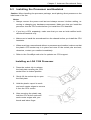
5-3 Installing the Processor and Heatsink
Caution: When handling the processor package, avoid placing direct pressure on the
label area of the fan.
Notes:
•Always connect the power cord last and always remove it before adding, re-
moving or changing any hardware components. Make sure that you install the
processor into the CPU socket before you install the CPU heatsink.
•If you buy a CPU separately, make sure that you use an Intel-certified multidirectional heatsink only.
•Make sure to install the serverboard into the chassis before you install the CPU
heatsinks.
•When receiving a serverboard without a processor pre-installed, make sure that
the plastic CPU socket cap is in place and none of the socket pins are bent;
otherwise, contact your retailer immediately.
•Refer to the CloudByte web site for updates on CPU support.
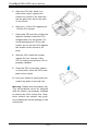
Installing an LGA 1356 Processor
1. Press the socket clip to release
the load plate covering the CPU
socket from its locked position.
2. Gently lift the socket clip to open
the load plate.
3. Hold the plastic cap at its north
and south center edges to remove
it from the CPU socket.
4. After removing the plastic cap,
hold the CPU at the north and
south center edges with your
thumb and index finger.
5-3
CloudByte ESA-A100 User's Manual
5. Align the CPU key, which is a
semi-circle cutout, against the
socket key, which is the notch below the gold color dot on the side
of the socket.
6. Align pin 1 of the CPU against pin
1 of the CPU socket.
7. Once both CPU and the socket are
aligned, carefully lower the CPU
straight down into the socket. (To
avoid damaging the CPU or the
socket, do not rub the CPU against
the surface of the socket or its
pins.)
8. With the CPU inside the socket,
inspect the four corners of the
CPU to make sure that the CPU is
properly installed.
9. Once the CPU is securely seated
on the socket, lower the CPU load
plate to the socket.
10.Use your thumb to gently push the
socket clip down to the clip lock.
Warning: Please save the plastic cap.
The serverboard must be shipped
with the plastic cap properly installed
to protect the CPU socket pins. Shipment without the plastic cap properly installed will cause damage to the
socket pins.
5-4
Chapter 5: Advanced Serverboard Setup
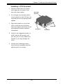
Installing a CPU Heatsink
1. Remove power from the system
and unplug the AC power cord
from the power supply.
Screw #1
(behind)
2. Do not apply any thermal grease
to the heatsink or the CPU die; the
required amount has already been
applied.
3. Place the heatsink on top of the
CPU so that the four mounting
holes are aligned with those on the
(preinstalled) heatsink retention
mechanism.
4. Screw in two diagonal screws (i.e.
the #1 and the #2 screws) until
just snug. Do not fully tighten the
screws or you may damage the
CPU.)
5. Add the two remaining screws
then finish the installation by fully
tightening all four screws.
5-5
Screw #4
Screw #3
Screw #2
Chapter 6 AMI BIOS
Chapter 6
BIOS
6-1 Introduction
This chapter describes the AMI BIOS Setup utility for the serverboard. It also provides the instructions on how to navigate the AMI BIOS Setup utility screens. The
AMI ROM BIOS is stored in a Flash EEPROM and can be easily updated.
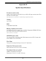
Starting BIOS Setup Utility
To enter the AMI BIOS Setup utility screens, press the <Del> key while the system
is booting up.
Note: In most cases, the <Del> key is used to invoke the AMI BIOS setup
screen. There are a few cases when other keys are used, such as <F3>,
<F4>, etc.
Each main BIOS menu option is described in this manual. The Main BIOS setup
menu screen has two main frames. The left frame displays all the options that can
be configured. Grayed-out options cannot be configured. Options in blue can be
configured by the user. The right frame displays the key legend. Above the key
legend is an area reserved for informational text. When an option is selected in the
left frame, it is highlighted in white. Often, informational text about the option will
display on the right.
Note: The AMI BIOS has default informational messages built in. The
manufacturer retains the option to include, omit, or change any of these
informational messages.
The AMI BIOS Setup utility uses a key-based navigation system called "hot keys."
Most of the AMI BIOS setup utility "hot keys" can be used at any time during setup
navigation. These keys include <F3>, <F4>, <Enter>, <ESC>, arrow keys, etc.
Note 1: In this section, options printed in Bold are default settings.
Note 2: <F3> is used to load optimal default settings. <F4> is used to save
the settings and exit the setup utility.
The AMI BIOS main menu displays the following information:
6-1
CloudByte ESA-A100 User's Manual
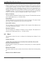
his feature displays the features that need to be enabled for the Intel Trusted
Execution Technology to work properly in the system.
VT-d Support: Intel Virtualization Technology with Direct I/O support
VT Support: Intel Virtualization Technology support
TPM Support: Trusted Platform support
TPM State: Trusted Platform state
Intel TXT (LT-SX) Dependencies
This feature displays the features that need to be enabled for the Intel Trusted
Execution Technology to work properly in the system.
VT-d Support: Intel Virtualization Technology with Direct I/O support
VT Support: Intel Virtualization Technology support
TPM Support: Trusted Platform support
TPM State: Trusted Platform state
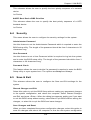
6-2 IPMI
Use this feature to configure Intelligent Platform Management Interface (IPMI)
settings.
IPMI Firmware Revision
This item indicates the IPMI firmware revision used in your system.
IPMI Status
This item indicates the status of the IPMI firmware installed in your system.
System Event Log
Enabling/Disabling Options
SEL Components
Select Enabled for all system event logging at bootup. The options are Enabled
and Disabled.
Erasing Settings
Erase SEL
6-2
Chapter 6 AMI BIOS
Select Yes, On next reset to erase all system event logs upon next system reboot.
Select Yes, On every reset to erase all system event logs upon each system reboot.
Select No to keep all system event logs after each system reboot. The options are
No, Yes, On next reset, and Yes, On every reset.
When SEL is Full
This feature allows the user to decide what the BIOS should do when the system
event log is full. Select Erase Immediately to erase all events in the log when the
system event log is full. The options are Do Nothing and Erase Immediately.
Custom EFI Logging Options
Log EFI Status Codes
Select Enabled to log EFI (Extensible Firmware Interface) Status Codes, Error
Codes or Progress Codes. The options are Enabled and Disabled.
Note: After making changes on a setting, be sure to reboot the system for
the changes to take effect.
BMC Network Configuration
LAN Channel 1: This feature allows the user to configure the settings for LAN1 Port.
IPMI LAN Selection: This feature displays the available IPMI LAN modes.
IPMI Network Link Status: This feature displays the IPMI Network Link status.
Update IPMI LAN Configuration
This feature allows the BIOS to implement any IP/MAC address changes at the next
system boot. If the option is set to Yes, any changes made to the settings below will
take effect when the system is rebooted. The options are No and Yes.
Configuration Address Source
6-3
CloudByte ESA-A100 User's Manual
This feature allows the user to select the source of the IP address for this computer.
If Static is selected, you will need to know the IP address of this computer and enter
it to the system manually in the field. If DHCP is selected, the BIOS will search for
a DHCP (Dynamic Host Configuration Protocol) server in the network that is attached to and request the next available IP address for this computer. The options
are DHCP and Static. The following items are assigned IP addresses automatically
if DHCP is selected, or can be configured manually if Static is selected.
Station IP Address
This item displays the Station IP address for this computer. This should be in decimal
and in dotted quad form (i.e., 192.168.10.253).
Subnet Mask
This item displays the sub-network that this computer belongs to. The value of each
three-digit number separated by dots should not exceed 255.
Station MAC Address
This item displays the Station MAC address for this computer. Mac addresses are
6 two-digit hexadecimal numbers.
Gateway IP Address
This item displays the Gateway IP address for this computer. This should be in
decimal and in dotted quad form (i.e., 192.168.10.253).
6-3 Boot
This submenu allows the user to configure the following boot settings for the
system.
Set Boot Priorities
1st Boot Device/2nd Boot Device/3rd Boot Device/4th Boot Device/5th
Boot Device/6th Boot Device
Use this feature to specify the sequence of boot priority for a device specified
by the user.
Delete Boot Option
This feature allows the user to select a boot device to delete from the boot priority
list.
Network Device BBS Priorities
6-4
Chapter 6 AMI BIOS
This submenu allows the user to specify the boot priority sequence of a network
device.
1st Device
UEFI Boot Device BBS Priorities
This submenu allows the user to specify the boot priority sequence of a UEFI
bootable device.
1st Device
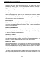
6-4Security
This menu allows the user to configure the security settings for the system.
Administrator Password
Use this feature to set the Administrator Password which is required to enter the
BIOS setup utility. The length of the password should be from 3 characters to 20
characters long.
User Password
Use this feature to set a User Password which is required to log into the system
and to enter the BIOS setup utility. The length of the password should be from 3
characters to 20 characters long.
Password Check
This feature allows the user to decide if a password is required to enter the BIOS
Setup utility or upon system boot. The options are Setup and Always.
6-5 Save & Exit
This submenu allows the user to configure the Save and Exit settings for the
system.
Discard Changes and Exit
Select this option to quit the BIOS Setup without making any permanent changes
to the system configuration, and reboot the computer. Select Discard Changes
and Exit, and press <Enter>. When the dialog box appears, asking you if you want
to exit the BIOS setup without saving, select Yes to quit BIOS without saving the
changes, or select No to quit the BIOS and save changes.
Save Changes and Reset
When you have completed the system configuration changes, select this option to
save the changes and reboot the computer so that the new system configuration
6-5
CloudByte ESA-A100 User's Manual
settings can take effect. Select Save Changes and Exit, and press <Enter>. When
the dialog box appears, asking you if you want to exit the BIOS setup without saving, select Yes to quit BIOS without saving the changes, or select No to quit the
BIOS and save changes.
Save Options
Save Changes
Select this option and press <Enter> to save all changes you've done so far and
return to the AMI BIOS utility Program. When the dialog box appears, asking you
if you want to save configuration, select Yes to save the changes, or select No to
return to the BIOS without making changes.
Discard Changes
Select this feature and press <Enter> to discard all the changes and return to the
BIOS setup. When the dialog box appears, asking you if you want to load previous values, select Yes to load the values previous saved, or select No to keep the
changes you've made so far.
Restore Optimized Defaults
Select this feature and press <Enter> to load the optimized default settings that
help optimize system performance. When the dialog box appears, asking you if you
want to load optimized defaults, select Yes to load the optimized default settings,
or select No to abandon optimized defaults.
Save as User Defaults
Select this feature and press <Enter> to save the current settings as the user's
defaults. When the dialog box appears, asking you if you want to save values as
user's defaults, select Yes to save the current values as user's default settings, or
select No to keep the defaults previously saved as the user's defaults.
Restore User Defaults
Select this feature and press <Enter> to load the user's defaults previously saved in
the system. When the dialog box appears, asking you if you want to restore user's
defaults, select Yes to restore the user's defaults previously saved in the system,
or select No to abandon the user's defaults that were previously saved.
Boot Override
This feature allows the user to override the Boot Option Priorities setting in the Boot
menu, and instead immediately boot the system with one of the listed devices. This
is a one-time override.
6-6