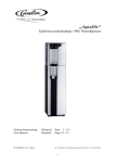
1
Radio Modems Wireless M-Bus AMR Transmitter / Repeater / Receiver User guide version V1.5.1 ADEUNIS RF 283 rue Louis Néel - Parc Technologique Pré Roux 38920 CROLLES - France Tel. : +33 (0)4 76 92 07 77 - Fax : +33 (0)4 76 04 80 87 www.adeunis-rf.com [email protected] Radio Modems Wireless M-Bus AMR - User guide version V1.5.1 INFORMATION Document information Title Radio Modems Wireless M-Bus AMR - User guide version V1.5.1 Sub-title Version 1.5.1 Document type implementation This document applies to the following products Name Reference Firmware version Wireless M-Bus transmitter AMR ARF7883AA (sub-assembly) V1.0 Wireless M-Bus transmitter AMR gas ARF7904 V1.0 Wireless M-Bus transmitter AMR water ARF7906 V1.0 Wireless M-Bus repeater AMR (main) ARF7923AA V1.0 Wireless M-Bus repeater AMR (battery) ARF7924AA V1.0 Wireless M-Bus receiver AMR (RS232) ARF7922BA V1.0 Wireless M-Bus receiver AMR (RS485) ARF7922CA V1.0 Wireless M-Bus receiver AMR (USB) ARF7922EA V1.0 Disclaimer This document and the use of any information contained therein, is subject to the acceptance of the Adeunis RF terms and conditions. They can be downloaded from www.adeunis-rf.com. Adeunis RF makes no warranties based on the accuracy or completeness of the contents of this document and reserves the right to make changes to specifications and product descriptions at any time without notice. Adeunis RF reserves all rights to this document and the information contained herein. Reproduction, use or disclosure to third parties without express permission is strictly prohibited. Copyright © 2012, Adeunis RF. Adeunis RF is a registered trademark in the EU and other countries. Technical Support Website Our website contains many useful information : modules and stand alone products information, user guides, configuration software and technical documents which can be accessed 24 hours a day. Email If you have technical problems or cannot find the required information in the provided documents, contact our Technical Support by email. Use our dedicated email address ([email protected]) rather than any personal email address of our staff. This makes sure that your request is processed as soon as possible. Helpful Information when Contacting Technical Support When contacting Technical Support please have the following information ready: • Product type (e.g. Wireless M-Bus transmitter AMR ref ARF7904A), • Firmware version (e.g. V1.2) • Clear description of your question or the problem • A short description of the application • Your complete contact details Page 2 of 23 Radio Modems Wireless M-Bus AMR - User guide version V1.5.1 DECLARATION OF CONFORMITY We ADEUNIS RF, 283 rue LOUIS NEEL, 38920 CROLLES, France declare under our own responsibility that the products Name Reference(s) Wireless M-Bus module ARF7883Ax, ARF7904Ax, ARF7906Ax, ARF7922x, ARF7923x, ARF7924x to which this declaration refers conform with the relevant standards or other standardising documents : • EN 300 220-2 (v2.3.1) (2010-02) • EN 60950-1 (2001) + A11 (2004) • EN 301 489-1 (v1.8.1) (2008-04) • EN 301 489-3 (v1.4.1) (2002-08) • EN 62311 (2008) According to the RTTE Directive 99/5/EC Notes: • Conformity has been evaluated according to the procedure describes in the part III of R&TTE directive • Receiver class (if applicable): 3. Crolles, 18 Novembre 2010Hervé Vincent, CEO Page 3 of 23 Radio Modems Wireless M-Bus AMR - User guide version V1.5.1 Table of contents INFORMATION2 Disclaimer2 Technical Support 2 DECLARATION OF CONFORMITY 2 INTRODUCTION6 Environmental recommendations 6 Warnings6 Disposal of waste by users in private households within the European Union 7 EINLEITUNG7 Hinweise zum Umweltschutz 7 Warnhinweise8 Entsorgung der Abfälle von Betreibern in Privathaushalten innerhalb der Europäischen Union 8 1. 1.1. 1.2. Introduction to Radio modem AMR Operation Modes Advantage of the AMR solution of Adeunis RF 2. 2.1. Wireless M-Bus Transmitter AMR The alert modes 2.1.1 Consumptions alert 2.1.2 Fraud alert Technical specifications 2.2.1 General characteristics 2.2.2 Autonomy 2.2.3 Radio characteristics 2.2.4 Standard frame format 2.2.4.01 W-MBUS addresses 2.2.5 Meters compatibility 2.2.6 Dimensions 2.2.7 Dismantling the housing 2.2.8 Correct positioning of the modems Implementation 2.3.1 Configuration of the radio modem AMR 2.3.2 Wiring of the product 2.3.2.01 Wiring of «2 wire Itron Cyble» - 1 meter 2.3.2.02 Wiring of «5 wire Itron Cyble» - 1 meter 2.3.2.03 Wiring of «4 wire Hydrometer/Sappel Izar» - 1 meter 2.3.2.04 Wiring of 2 x Water meters version 2.3.2.05 Wiring of «Elster BK or Itron Gallus» - 1 gas meter 2.3.2.06 Wiring of 2 gas meters 2.3.3 Startup of the Radio modem AMR Modes 2.4.1 Operating mode 2.4.2 Alarm mode 2.5. Sensor(s) installation on meter 2.5.1 ITRON water meter 2.5.2 Hydrometer/Sappel water meter 2.5.3 Elster gas meter 2.5.4 ITRON Gallus gas meter 9 10 10 10 10 10 10 10 10 11 11 11 12 12 12 12 13 14 14 15 15 16 16 16 17 17 17 17 17 18 18 19 Wireless M-Bus Repeater AMR Technical specifications 3.1.1 Products 20 20 20 2.2. 2.3. 2.4. 3. 3.1. 9 9 9 Page 4 of 23 Radio Modems Wireless M-Bus AMR - User guide version V1.5.1 3.2. 4. 4.1. 4.2. 4.3. 5. 3.1.2 General characteristics 3.1.3 Radio characteristics Implementation of Wireless M-Bus repeater AMR 3.2.1 Wireless M-Bus repeater AMR (main) 3.2.2 Wireless M-Bus repeater AMR (battery) 20 20 20 20 21 Wireless M-Bus Receiver AMR Technical specifications 4.1.1 Products 4.1.2 General characteristics 4.1.3 Radio characteristics Implementation of Wireless M-Bus receiver AMR 4.2.1 Wireless M-Bus receiver AMR RS232 4.2.2 Wireless M-Bus receiver AMR RS485 Wireless M-Bus DATA format 4.3.1 Frame format 4.3.2 Optional second block 4.3.3 Optional other block 4.3.4 L : Length field 4.3.5 C : Control Field 4.3.6 M: Manufacturer ID Field 4.3.7 A : Address 4.3.8 CI : Control Information Field 4.3.9 CRC: Cyclic Redundancy Check 4.4. Serial ports wiring 4.4.1 RS232 serial port 4.4.2 RS485 serial port 21 21 21 21 21 21 21 22 22 22 22 22 22 22 22 22 22 23 23 23 23 Version history 23 Page 5 of 23 Radio Modems Wireless M-Bus AMR - User guide version V1.5.1 INTRODUCTION All rights to this manual are the exclusive property of ADEUNIS RF. All rights reserved. Copying this manual (without written permission from the owner) via printing, copying, recording or by any other means, translating this manual (in full or partially) into any other language, including all programming languages, using any electrical, mechanical, magnetic or optical devices, manually or any by other methods, is prohibited. ADEUNIS RF reserves the right to change the technical specifications or functions of its products, or to cease manufacturing any of its products, or to cease technical support for one of its products without notice in writing and urges its customers to make sure that the information they have is valid. ADEUNIS RF configuration software and programs are available free of charge in a non-modifiable version. ADEUNIS RF can make no guarantees, including guarantees concerning suitability and applicability for a certain type of application. Under no circumstances can the manufacturer, or the distributor of an ADEUNIS RF program, be held liable for any damage caused by the use of the aforesaid program. Program names, as well as all copyright relating to programs, are the exclusive property of ADEUNIS RF. Any transfer, granting of licences to a third party, leasing, hire, transport, copying, editing, translation, modification into another programming language or reverse engineering are prohibited without ADEUNIS RF’s prior written authorisation and consent. ADEUNIS RF 283, rue Louis Néel 38920 Crolles France Telephone +33 (0)4 76 92 07 77 Fax +33 (0)4 76 08 97 46 Environmental recommendations All superfluous packaging materials have been eliminated. We have done everything possible to make it easy to separate the packaging into three types of materials: cardboard (box), expanded polystyrene (filler material) and polyethylene (packets, foam protective sheets). Your device is composed of materials that can be recycled and reused if it is dismantled by a specialist company. Please observe local regulations concerning the manner in which waste packaging material, used batteries and your obsolete equipment are disposed of. Warnings Valid for Wireless M-Bus module with the following references: ARF7883Ax, ARF7904Ax, ARF7906Ax, ARF7922x, ARF7923x, ARF7924x Read the instructions in the manual. The safety of this product is only guaranteed when it is used in accordance with its purpose. Maintenance should only be carried out by qualified persons. Please note, do not install the equipment close to a heat source or in damp conditions. Please note, when the equipment is open, do not carry out any operations other than those specified in these instructions. Only use this equipment inside a building and at a maximum height of 2000 m above sea level. Please note: do not open the product as there is a risk of electric shock. Please note: for your own safety, you must ensure that the equipment is switched off before carrying out any work on it. Please note: For your safety, the power supply circuit must be SELV (Safety Extra Low Voltage) and must be a limited power sources. (Conform to chapter 2.5 of the 60950-1 standard) Please note: when the aerial is installed outside, it is essential to connect the cable screen to the building’s earth. We recommend using lightning protection. The protection kit chosen must permit the coaxial cable to be earthed (eg: coaxial lightning arrester with earthing of the cable at different places on the aerial at the base of pylons and at the entry, or just before entering the premises). The product must be equipped with a switching mechanism so that the power can be cut. This must be close to the equipment. For repeater ARF7923AA (mains version), the disconnect device in case of a problem is the AC / DC adapter, it must be easily accessible. Page 6 of 23 Radio Modems Wireless M-Bus AMR - User guide version V1.5.1 Any electrical connection of the product must be equipped with a protection device against voltage spikes and short-circuits. Recommendations regarding use • • • • • • • • • Before using the system, check that the power supply voltage shown in the user manual corresponds to your supply. If it doesn’t, please consult your supplier. Place the device against a flat, firm and stable surface. The device must be installed in a location that is sufficiently ventilated so that there is no risk of internal heating and it must not be covered with objects such as newspapers, cloths, curtains, etc. The device’s aerial must be free and at least 10 cm away from any conducting material. The device must never be exposed to heat sources such as heating equipment. Do not place the device close to objects with naked flames such as lit candles, blowtorches, etc. The device must not be exposed to aggressive chemical agents or solvents likely to damage the plastic or corrode the metal parts. Install your device close to its DC power supply. Avoid electrical and RS232 extension cables over 3 metres in length. Disposal of waste by users in private households within the European Union This symbol on the product or on its packaging indicates that this product must not be disposed off with your other household waste. Instead, it is your responsibility to dispose of your waste by taking it to a collection point designated for the recycling of electrical and electronic appliances. Separate collection and recycling of your waste at the time of disposal will contribute to conserving natural resources and guarantee recycling that respects the environment and human health. For further information concerning your nearest recycling centre, please contact your nearest local authority/town hall offices, your household waste collection company or the shop where you bought the product. EINLEITUNG Alle Rechte an diesem Handbuch sind das alleinige Eigentum der ADEUNIS RF. Alle Rechte sind vorbehalten. Jede (ohne die schriftliche Genehmigung des Eigentümers erfolgende) Wiedergabe dieses Handbuches durch Druck, Kopie, Aufzeichnung oder jedwedes andere Mittel sowie die (vollständige oder teilweise) Übersetzung in jede andere Sprache einschließlich aller Programmiersprachen durch Verwendung welcher elektrischer, mechanischer, magnetischer, optischer, manueller Vorrichtungen oder anderen Methoden auch immer, sind verboten. Die ADEUNIS RF behält sich das Recht vor, ohne irgendeine schriftliche Mitteilung die technischen Spezifikationen oder die Funktionen ihrer Produkte zu verändern, bzw. die Herstellung eines ihrer Produkte einzustellen oder den technischen Support für eines ihrer Produkte auszusetzen und bittet ihre Kunden inständig sich zu vergewissern, dass die ihnen zur Verfügung stehenden Informationen zutreffend sind. Die Konfigurations- und Programmsoftware der ADEUNIS RF steht kostenlos in einer Version zur Verfügung, die nicht verändert werden kann. Die ADEUNIS RF kann keinerlei Garantie und auch keine Garantie zur Eignung und Anwendbarkeit für eine Applikation bestimmten Typs gewähren. Der Hersteller oder der Verkäufer eines Programms der ADEUNIS RF kann in keinem Fall für irgendwelche Schäden haftbar gemacht werden, die durch die Anwendung des besagten Programms gegebenenfalls verursacht werden könnten. Die Bezeichnungen der Programme sowie alle Urheberrechte zu den Programmen sind das alleinige Eigentum der ADEUNIS RF. Jede Übertragung, Gewährung von Lizenzen an einen Dritten, Leasingvergabe, Vermietung, Übereignung, Kopie, Übersetzung, Modifizierung in eine andere Programmiersprache oder durch ein Reverse Engineering ist ohne die schriftliche Genehmigung und ohne das Einverständnis der ADEUNIS RF verboten. ADEUNIS RF 283, rue Louis Néel 38920 Crolles France Tel +33 (0)4 76 92 07 77 Fax +33 (0)4 76 08 97 46 Hinweise zum Umweltschutz Alle überflüssigen Verpackungsmaterialien wurden vermieden. Wir haben auch alles getan, was uns möglich ist, damit die Verpackung ohne Weiteres in drei Typen von Werkstoffen getrennt werden kann : Karton (die Schachtel), geschäumtes Polystyrol (Dämmmaterial) und Polyäthylen (Beutel, Schaumfolie zum Schutz). Ihr Gerät besteht aus Werkstoffen, die recycelt und weiterverwendet werden können, wenn es von einem darauf spezialisierten Unternehmen demontiert wird. Beachten Sie bitte die jeweils geltenden örtlichen Vorschriften zur Entsorgung der Verpackungsmaterialien, der verbrauchten Batterien und Ihres ausgemusterten Gerätes. Page 7 of 23 Radio Modems Wireless M-Bus AMR - User guide version V1.5.1 Warnhinweise Gültig für die Relaisempfänger mit den Artikelnummern ARF7883Ax, ARF7904Ax, ARF7906Ax, ARF7922x, ARF7923x, ARF7924x Lesen Sie die Anleitungen dieses Handbuches. Die durch dieses Produkt gewährte Sicherheit kann nur bei einer Anwendung entsprechend dem vorgesehenen Einsatzzweck gewährleistet werden. Die Wartung darf nur von einem entsprechend geschulten Personal vorgenommen werden. Achtung ! Die Geräte dürfen nicht in der Nähe einer Wärmequelle oder einer Quelle von Feuchtigkeit installiert werden. Achtung ! Wenn das Gerät geöffnet ist, dürfen nur die in dieser Anleitung vorgesehenen Arbeiten ausgeführt werden. Dieses Gerät darf nur innerhalb eines Gebäudes und in einer Höhe von nicht mehr als 2000 m eingesetzt werden. Achtung ! Das Gerät nicht öffnen ! Es besteht die Gefahr elektrischer Schläge. Achtung ! Zu Ihrer eigenen Sicherheit ist es unerlässlich, das Gerät vor jedem technischen Eingriff spannungsfrei zu schalten. Achtung ! Zu Ihrer eigenen Sicherheit die Stromversorgung Schaltung muss SELV (Safety Extra Low Voltage) sein und muss der beg renzten Stromquellen sein. Achtung ! Wenn die im Freien befindliche Antenne angeschlossen ist, muss die Abschirmung des Kabels unbedingt an die Gebäudeerde angeschlossen sein. Es wird empfohlen, einen Blitzschutz zu verwenden. Die Schutzeinrichtung muss eine Erdung des Koaxialkabels erlauben (z. B. koaxialer Blitzs chutz mit Erdung des Kabels an unterschiedlichen Stellen im Bereich der Antenne am Fuß des Mastes und am Eingang oder unmittelbar vor der Einführung in den Raum). Das Produkt muss mit einem Trennschalter versehen sein, um die Stromversorgung abschalten zu können. Diese Vorrichtung muss sich in der Nähe des Gerätes befinden. Im Produkt treten neben der Stromversorgung auch andere gefährliche Spannungen auf. Vor jedem Eingriff sind diese Spannungen ebenfalls abzuschalten. Jeder elektrische Anschluss des Gerätes muss mit einer Vorrichtung zum Schutz gegen Überlastungen und Kurzschlüsse versehen sein. Für Repeater ARF7923AA (Stromnetz-Version), die Trennvorrichtung im Falle eines Problems die AC / DC-Adapter ist, muss sie leicht zugänglich sein. Empfehlungen für den Einsatz • • • • • • • • • Vor dem Einsatz des Systems müssen Sie überprüfen, dass die in der Bedienungsanleitung angegebene Anschlussspannung den Werten Ihrer Stromversorgung entspricht. Anderenfalls wenden Sie sich bitte an Ihren Lieferanten. Stellen Sie das Gerät auf einer ebenen, festen und stabilen Fläche auf. Um jede Gefahr einer inneren Erwärmung des Gerätes zu vermeiden, ist dieses an einem gut belüfteten Ort aufzustellen und darauf zu achten, dass keine Gegenstände wie Zeitschriften, Matten, Vorhänge u. a. darauf abgelegt werden. Die Antenne des Gerätes muss frei liegen und von jeglichen leitenden Werkstoffen mindestens 10 cm entfernt sein. Das Gerät darf niemals der Einwirkung von Wärmequellen oder Heizgeräten ausgesetzt sein. Das Gerät darf sich niemals in der Nähe von Gegenständen mit offener Flamme befinden, wie brennenden Kerzen, Schweißbrennern usw. Das Gerät darf niemals der Einwirkung von aggressiven Chemikalien oder Lösemittel ausgesetzt werden, die geeignet sein könnten, den Kunststoff zu beschädigen oder die Metallteile zu korrodieren. Stellen Sie Ihr Gerät in der Nähe der Quelle seiner Spannungsversorgung DC auf. Vermeiden Sie bei Stromversorgung und RS232 Kabelverlängerungen mit einer Länge von mehr als 3 m. Entsorgung der Abfälle von Betreibern in Privathaushalten innerhalb der Europäischen Union Dieses Symbol auf dem Produkt oder auf seiner Verpackung weist darauf hin, dass dieses Produkt nicht gemeinsam mit Ihrem anderen Haushaltsmüll entsorgt werden darf. Stattdessen haben Sie dafür Sorge zu tragen, Ihre Abfälle bei einer Erfassungsstelle zu entsorgen, die auf das Recycling elektrischer und elektronischer Geräte spezialisiert ist. Die gesonderte Erfassung und das Recycling ihrer Abfälle bei der Entsorgung tragen dazu bei, die natürlichen Ressourcen zu bewahren und ein Recycling zu gewährleisten, das dem Schutz der Umwelt und der menschlichen Gesundheit dient. Für weitere Informationen zu der Ihrer Wohnung am nächsten gelegene Recyclingstelle wenden Sie sich bitte an die örtliche Gemeindeverwaltung, an die zuständige Dienststelle für die Müllabfuhr oder an das Geschäft, in dem sie das Gerät gekauft haben Page 8 of 23 Radio Modems Wireless M-Bus AMR - User guide version V1.5.1 1. Introduction to Radio modem AMR The Wireless M-Bus radio modems AMR (Automatic Meter Reading) from Adeunis RF range allow you to create an independent ecosystem to ensure the emission, transport and collection of consumption index using Wireless M-Bus protocol. This range is made of three products, all available in several version (see ¶ Informations). • • • Wireless M-Bus transmitter AMR : allows to transmit data (index) from water & gas meters. Wireless M-Bus repeater AMR : allows to repeat Wireless M-Bus frames and extend the range over several kilometers. Wireless M-Bus receiver AMR : allows to receive consumption data from Wireless M-Bus transmitters AMR or Wireless M-Bus repeater AMR and transit them to any collection device and / or operating data with a RS232 or RS485 serial port. 1.1. Operation Modes The products of the Adeunis-RF AMR range can adapt to all types of network topologies and all modes of Automatic Meter Reading. Pedestrian or vehicle modes : a transmission period of 10s allows to retrieve information from the entire meter fleet on a receptor such as mobile PC, Tablet, Smartphone or industrial PDA. This information will be available for a vehicle rolling up about 30 to 50 km / h according to the configuration of the installation. Fixed network mode : the receiver is permanently on the site and a data transmission every 10 minutes or 12 hours is more than enough for most applications, the specific historical (by time slot of 30 minutes) of consumption being sent every 12 hours. That said, the 10s configuration program can be used with a fixed network in order to obtain a very precise historical consumption on the receiver. 1.2. Advantage of the AMR solution of Adeunis RF The AMR solution of Adeunis RF is 100% compatible with the Wireless M-Bus (EN13757-3 and EN13757-4) standard. It’s an open standard where all the information needed to decode frames are present in the header of the frame itself, so no hidden information or impossible to interpret. In the frame, you will find information: Manufacturer, serial number, meter type, size of the index and the index itself. This is absolutely essential as a receiver / collector will have to deal with several different meters (water, gas, electricity, energy, ...) coming from several places (appartments, houses). The Wireless M-Bus radio modems AMR from Adeunis RF fit most meters on the market. It automatically adjusts Wireless M-Bus frame settings and format of the index to the selected meter and sensor. The Wireless M-Bus module of Adeunis RF, integrated in a product receiver of a portable or fixed (for example, Receiver AMR, a box or GPRS / ADSL collector), allows obviously to receive all information from Radio modems AMR. 2. Wireless M-Bus Transmitter AMR • • • • • • The connection the the meters is simple via a system compatible with pulse interface. The configuration is intuitive via mechanical switches. Two meters can be supported by a single transmitter AMR from Adeunis RF, allowing a significant reduction of costs of implementation and deployment. This version features a application to adjust the data transmission cycle, manage a history of consumption, to inform the leaks and alert on fraud. This document contains key recommendations for an optimal implementation of AMR transmitters from ADEUNIS RF. Compliance with these recommendations will help you get a communication distance advertised by the manufacturer depending on the model chosen. These products are 100% compatible with European Wireless M-Bus protocol (EN13757-4 and EN13757-3), and use the T1 mode at a frequency of 868.950MHz. These products use a lithium battery to ensure a long product life more than 12 years under standard conditions of use. Note: By default, the radio modems AMR use T1 mode (868.950MHz). If you want to use another mode (S1, R1) thank you for contacting us Page 9 of 23 Radio Modems Wireless M-Bus AMR - User guide version V1.5.1 2.1. The alert modes 2.1.1 Consumptions alert In the case of overconsumption, an alert is sent by radio to indicate an abnormality. This avoids endless litigation with the subscriber, and can rapidly stop the problem. Similarly, a very low consumption rate (but permanent), probably indicates a leak. In this case an alert is also sent. 2.1.2 Fraud alert In case of the measuring cable failure, removal of the sensor or of a permanent magnetic field on the consumption sensor, an alert is sent by radio to the receiver. 2.2. Technical specifications 2.2.1 General characteristics Parametre Value Operating voltage 3.6V nominal Consumption max. 150mA Power supply Pile Li-SOCl2 Operating temperature -25°C / +70°C Dimensions 145 x 100 x 40 Case IP 65 Radio standards EN 300-220, EN 301-489, EN 60950, EN 13757-3 and EN 13757-4 2.2.2 Autonomy Battery type Mode Periodicity Sensor number Autonomy Li-SOCl2 T1 10 sec 1 12 years Li-SOCl2 T1 10 sec 2 12 years Li-SOCl2 T1 10 min 1 12 years Li-SOCl2 T1 10 min 2 12 years Li-SOCl2 T1 12 h 1 12 years Li-SOCl2 T1 12 h 2 12 years 2.2.3 Radio characteristics Module type RF power Sensitivity (if Adeunis RF receiver) RF data rate range W-Mbus 14dBm (25mW) -110 dBm mode T1 100 kbps up to 600m 2.2.4 Standard frame format Periodic frames Wireless M-Bus issued by AMR modems are compliant with EN13757-4 and EN13757-3, and can be received by any Wireless M-Bus receiver (interoperability). All necessary information are present in the RF frame. The end of the serial number of radio modems AMR, in each RF frame, indicate the type of counter: 07 for water and 03 for gas. The value of the index, according to the standard Wireless M-Bus is indicated in the field DATA VARIABLE DATA BLOCK Field (see doc EN137573). For all meter types, the size of the index (without offset) is always of the form 32-bit binary / hex according to the standard, with a unit volume of 0.1 liter for water meter and 0.1 dm3 for gas meters. Page 10 of 23 Radio Modems Wireless M-Bus AMR - User guide version V1.5.1 2.2.4.01 W-MBUS addresses The unique Wireless M-Bus address is emitted with each radio frame, and is different for each of the meters. In the case of a modem with 2 meters inputs, input 1 will always has a form such as ARF1X XX XX XX XX and input 2 a form such as ARF2X XX XX XX XX X is a shift of the unique address. Addresses are listed on the label on the back of modems AMR. 2.2.5 Meters compatibility Type Name Meter type Meter pulse weight Itron Cyble Aquadis TD8 Flodis Flostar M Woltex M Woltmag M (from 1996) K=1, 10 and 100 liters Water Hydrometer/Sappel Izar Aquarius Altaïr Aquila Corona M K=1, 10 and 100 liters Gas Elster BK BK-G1.6M BK-2.5M BK-G4M (from 1998) 10 and 100dm3 Gas Itron Gallus G1.6 G2.5 G4 (from 1998) 10 and 100dm3 Water 2.2.6 Dimensions Page 11 of 23 Radio Modems Wireless M-Bus AMR - User guide version V1.5.1 2.2.7 Dismantling the housing To wire these products, the lower part of the housing must be opened by removing the two stainless steel screws on each side of the box. 2.2.8 Correct positioning of the modems To optimize radio ranges, install the modem at a minimum height of 1.50m and not stuck to the wall, ideally shifted 20 cm (5 to 10 cm minimum), and if possible near an opening. YES 2.3. Implementation Before starting the implementation of the system, verify that the sensors correspond to the meters on which you install them. To implement the product, you must first unscrew the 2 screws on the bottom of the box, then open the case to access the terminals and switch configuration. 2.3.1 Configuration of the radio modem AMR By default, AMR modems are shipped pre-configured according to user requests. Indeed, once fed, it is not possible to reconfigure products. This configuration lock is the ideal way to prevent fraud to reduce consumption values via a new configuration For more information, please find below the different configurations. AMR modem must be configured in accordance with the sensor to connect (beware pulse weight) and according to the desired output frequency, according to the table below. Page 12 of 23 Radio Modems Wireless M-Bus AMR - User guide version V1.5.1 For example, an Itron Cyble sensor with a pulse weight of1L (KLF: 1) and an emission period of 10MN must be configured as : - switch1 : On switch2 : On switch3 : On switch4 : Off CONFIGURATION TABLE : Type Gas Water SW1 SW2 SW3 SW4 Off Off Off Off Pulse weight 100 dm3 /Periodicity sending frame index = 10s Configuration Off Off Off On Pulse weight 100 dm3 /Periodicity sending frame index = 12h Off Off On Off Pulse weight 100 dm3 /Periodicity sending frame index = 10s Off Off On On Pulse weight 100 dm3 /Periodicity sending frame index = 10min Off On Off Off Pulse weight 100 dm3 /Periodicity sending frame index = 12h Off On Off On Pulse weight 10 dm3 /Periodicity sending frame index = 10s Off On On Off Pulse weight 10 dm3 /Periodicity sending frame index = 10min Off On On On Pulse weight 10 dm3 /Periodicity sending frame index = 12h On Off Off Off Pulse weight 100 L /Periodicity sending frame index = 10s On Off Off On Pulse weight 100 L /Periodicity sending frame index = 12h On Off On Off Pulse weight 10 L /Periodicity sending frame index = 10s On Off On On Pulse weight 10 L /Periodicity sending frame index = 10min On On Off Off Pulse weight 10 L /Periodicity sending frame index = 12h On On Off On Pulse weight 1 L /Periodicity sending frame index = 10s On On On Off Pulse weight 1 L /Periodicity sending frame index = 10min On On On On Pulse weight 1 L /Periodicity sending frame index = 12h 2.3.2 Wiring of the product Slide the sensor(s) or cable (s) through the gland. Warning, there are different housing versions for 1 or 2 sensors. For connection procedure, connect all wires and finish by the green wire (mandatory). 4 configuration switches Switch 1 ON = water OFF = gas Green LED : startup and operation status Meter #1 pulse : white GND meter#1 : brown Fraud meter#1 : green Direction meter#1 : grey* «sens/HF» meter#1 : yellow* «sens/HF» meter#2 : yellow* Direction meter#2 : grey* Fraud meter#2 : green GND meter#2 : brown Meter #2 pulse : white * : depending on configuration Page 13 of 23 Radio Modems Wireless M-Bus AMR - User guide version V1.5.1 2.3.2.01 Wiring of «2 wire Itron Cyble» - 1 meter - Water Procedure : • Open the housing of the modem AMR and remove the bottom (two screws) • Insert the cables through the cable gland located on the bottom part of the housing • Set switch 1 to ON • Connect the white cable to IMP1 • Connect the brown cable to GND • Back ground green wire (FRD1) on the GND of the sensor • Close the housing and tighten the screws • Tighten the gland nut to ensure sealing Note : Always connect the green wire (fraud) last ! 2.3.2.02 Wiring of «5 wire Itron Cyble» - 1 meter - Water Procedure : • Open the housing of the modem AMR and remove the bottom (two screws) • Insert the cables through the cable gland located on the bottom part of the housing • Set switch 1 to ON • Connect the white cable to IMP1 • Connect the brown cable to GND • Connect the grey wire to DIR1 • Connect the yellow wire to S/HF1 • Connect the green wire to FRD1 • Close the housing and tighten the screws • Tighten the gland nut to ensure sealing Note : Always connect the green wire (fraud) last ! Page 14 of 23 Radio Modems Wireless M-Bus AMR - User guide version V1.5.1 2.3.2.03 Wiring of «4 wire Hydrometer/Sappel Izar» - 1 meter - Water Procedure : • Open the housing of the modem AMR and remove the bottom (two screws) • Insert the cables through the cable gland located on the bottom part of the housing • Set switch 1 to ON • Connect the white cable to IMP1 • Connect the brown cable to GND • Connect the yellow wire to S/HF1 • Connect the green wire to FRD1 • Close the housing and tighten the screws • Tighten the gland nut to ensure sealing Note : Always connect the green wire (fraud) last ! 2.3.2.04 Wiring of 2 x Water meters version Wire the same way as for versions 1 meter: symmetry with respect to the axis of the block. Procedure : • Open the housing of the modem AMR and remove the bottom (two screws) • Insert the cables through the cable gland located on the bottom part of the housing • Set switch 1 to ON • Connect the white cable to IMP1 • Connect the brown cable to GND • Connect the grey wire to DIR1 • Connect the yellow wire to S/HF1 • Connect the green wire to FRD1 • Connect the white cable to IMP2 • Connect the brown cable to GND • Connect the grey wire to DIR2 • Connect the yellow wire to S/HF2 • Connect the green wire to FRD2 • Close the housing and tighten the screws • Tighten the gland nut to ensure sealing Note : Always connect the green wire (fraud) last ! Page 15 of 23 Radio Modems Wireless M-Bus AMR - User guide version V1.5.1 2.3.2.05 Wiring of «Elster BK or Itron Gallus» - 1 gas meter Procedure : • Open the housing of the modem AMR and remove the bottom (two screws) • Insert the cables through the cable gland located on the bottom part of the housing • Set switch 1 to OFF • Connect the white cable to IMP1 • Connect the brown cable to GND • Connect the green wire to FRD1 • Close the housing and tighten the screws • Tighten the gland nut to ensure sealing Note : Always connect the green wire (fraud) last ! 2.3.2.06 Wiring of 2 gas meters Procedure : • Open the housing of the modem AMR and remove the bottom (two screws) • Insert the cables through the cable gland located on the bottom part of the housing • Set switch 1 to OFF • Connect the white cable to IMP1 • Connect the brown cable to GND • Connect the green wire to FRD1 • Connect the white cable to IMP2 • Connect the brown cable to GND • Connect the green wire to FRD2 • Close the housing and tighten the screws • Tighten the gland nut to ensure sealing Note : Always connect the green wire (fraud) last ! 2.3.3 Startup of the Radio modem AMR The actual start of the product is automatically 10 seconds after connecting wire fraud, and any subsequent changes on switches will not have any effect. (Be careful though of malfunctions caused by improper positioning of switch1 on the type of sensor connected). The green LED will flash for 30 seconds, turn ON 1 second and OFF 1 second to indicate the correct startup of the counting function. The same scenario will happen again if you subsequently connect the 2nd counter. When installing sensors on the meters, the value of the mechanical index is never zero (even with brand new meters because they are always tested through a few dozen rotations on a test bench); this difference is not supported by the modem AMR and must therefore treat offset through the receiving tool. Page 16 of 23 Radio Modems Wireless M-Bus AMR - User guide version V1.5.1 Note: For gas meters, it may be that the modem AMR starts with a non-zero value (related to the principle of magnetic detection). Be sure to check the offset value after startup. if an offset correction must be applied, it must be done on the collector (receiever side). It’s not possible to and apply a coorection on the Radio Modem AMR. 2.4. Modes 2.4.1 Operating mode In run mode, the green LED flashes briefly every 4 seconds. Similarly, it also flashes briefly when sending RF frame, so all 10s, 12 or 10 minutes depending on the configuration. In addition to these standard frames and receivable by other equipment Wireless M-Bus Other T1 mode, frames of historical consumption on the day, week, month, year in court, as well as the last 3 years are émisses every 12 hours. Our support service is at your disposal for any information on the implementation of this function and the associated frame format. 2.4.2 Alarm mode Radio Modems AMR are equipped, according to the sensor configurations, of systems for detecting fraud. • On Itron Cyble 5 wire and Sappel 3 and 4 wire water versions, a cable break detection is performed every 4 seconds, and indicates a temporary fraud in the radio frame if the fraud happened only one time, and indicates permanent fraud if it has been viewed 2 times or more. • On Itron Gallus gas versions a cable cut detection is present. • On Elster gas versions, in addition of the cable break detection, you’ll find a fraud detection by magnetic field. 2.5. Sensor(s) installation on meter The sensors must be installed on different counters with fixing systems provided. 2.5.1 ITRON water meter For Itron water meters, open the covers meter, remove the protective cap located on the surface of the meter. Then attach the box Cyble sensor using the supplied screw by using the meter boss as centering element. Then positioning the protective blue cover over the crew. Cenetering and fixing screw Page 17 of 23 Radio Modems Wireless M-Bus AMR - User guide version V1.5.1 2.5.2 Hydrometer/Sappel water meter For Sappel water meters, remove the covers, fix the Izar Sensor on the meter, and then perform a quarter turn on the black screw with a screwdriver. Fixing screw 2.5.3 Elster gas meter With Elster gas meters, install the sensor in the housing provided for this purpose under the counter (first drag the left and right side up), and finally stopping the system with the supplied accessories. Sealing system Page 18 of 23 Radio Modems Wireless M-Bus AMR - User guide version V1.5.1 2.5.4 ITRON Gallus gas meter For Itron gas meters, install the sensor in the housing provided for this purpose under the counter, and then screw the metal screw using a flat screwdriver. Fixing screw Page 19 of 23 Radio Modems Wireless M-Bus AMR - User guide version V1.5.1 3. Wireless M-Bus Repeater AMR The Wireless M-Bus repeater AMR (Automatic Meter Reading) from Adeunis RF is a ready-tu-use system allowing to repeat radio frames from Wireless MBus transmitters. This repeater can double the range of Wireless M-Bus transmitters AMR and thus ensure a seamless transmission of radio frames in harsh environments or when the data concentrator is distant. By combining several Wireless M-Bus repeaters AMR, Adeunis RF extends the transport of transmitted frames over several kilometers. The repeater is available in two versions : • Main power supply : T1 mode (S1 or R1 on demand) • Battery power supply : T1 3.1. Technical specifications 3.1.1 Products Name Reference Firmware version Wireless M-Bus repeater AMR (main) ARF7923AA V1.0 Wireless M-Bus repeater AMR (battery) ARF7924AA V1.0 3.1.2 General characteristics Parameters Value Repetition capacity T1 mode: up to 200 products repeated S1 mode: up to 60 products repeated R1 mode: up to 30 products repeated Number of repeaters Without limitation if coverage zone is respected Power Main version : through ANSMANN APS300 power supply: 3Vdc (2,7Vdc min ; 3,3Vdc max) -> maximum operating temperature : 25°C Battery version : Li-SOCl2 Operating voltage (battery version) 3.6V nominal Consumption max. 150mA Operating temperature -25°C / +70°C Dimensions 145 x 100 x 40 Case IP 65 Radio standards EN 300-220, EN 301-489, EN 60950, EN 13757-3 and EN 13757-4 3.1.3 Radio characteristics Module type RF power Sensitivity (if RX Adeunis RF) data rate Range Wireless M-Bus 14dBm (25mW) -110 dBm T1 mode 100 kbps up to 600m 3.2. Implementation of Wireless M-Bus repeater AMR 3.2.1 Wireless M-Bus repeater AMR (main) The repeater (main version) is factory configured in T1 mode (modes S1 and R1 are available on request). For the implementation, simply connect the AC adapter, check that the operation LED power (located under the housing) is active, and the repeater will repeat any frames RF mode concerned about 5 seconds after receipt of the initial frame. At power up, the green LED will flash for 10/15 seconds alternately 1 second ON and 1 second OFF to indicate the correct startup of the repeat function. We can cascade several repeaters to extend the transmission distance. Be careful though not to install more than 2 repeaters in the same «zone» of radio coverage as this will cause an excess of RF frame. Page 20 of 23 Radio Modems Wireless M-Bus AMR - User guide version V1.5.1 Caution: Do not attempt to use an AC adapter other than the one supplied with the product. 3.2.2 Wireless M-Bus repeater AMR (battery) The battery repeater can repeat all Wireless M-Bus frame, provided they conform to EN13757 standards and that the transmission mode is T1 mode. The battery repeater is configured to listen to a daily 4 min and 10 seconds , by default Under these conditions, we can use a few dozens of transmitters per repeaters maintaining a long life Battery type Mode Daily repetition Autonomy Reference Li-SOCl2 T1 250 sec (4mn and 10 sec) 8 years ARF7924AA Li-SOCl2 T1 180 sec (3mn) 10 years on demand 4. Wireless M-Bus Receiver AMR The Wireless M-Bus Receiver AMR (Automatic Meter Reading) from Adeunis RF is a ready-to-use system allowing to receive consumption data from Wireless M-Bus transmitters AMR or Wireless M-Bus repeater AMR. This receiver can acquire Wireless M-Bus frames and transit them to any collection device and / or operating data with a RS232 or RS485 serial port. At first switch on, by default, the AMR RECEIVER is set to : T1 «Other». Serial port parameters : 115.2kbps / 8bits / no parity The Product is ready to use without any configuration needed. 4.1. Technical specifications 4.1.1 Products Name Reference Firmware version Wireless M-Bus receiver AMR (RS232) ARF7922BA V1.0 Wireless M-Bus receiver AMR (RS485) ARF79222CA V1.0 Wireless M-Bus receiver AMR (USB) ARF7922EA V1.0 4.1.2 General characteristics Parameters Value Serial port data rate 115.2kbps (8N1) Power supply Main through provided power supply Operating temperature -40°C / +85°C Dimensions 145 x 100 x 40 Case IP 65 Standards EN 300-220, EN 301-489, EN 60950, EN 13757-3 et EN 13757-4 4.1.3 Radio characteristics Module type RF power Sensitivity (if RX Adeunis RF) data rate Range Wireless M-Bus 14dBm (25mW) -110 dBm mode T1 100 kbps - 4.2. Implementation of Wireless M-Bus receiver AMR 4.2.1 Wireless M-Bus receiver AMR RS232 By default, the receiver is configured for T1 mode. Simply connect power and serial port and all T1 Wireless M-Bus frames will be transmitted on the RS232 serial link (frame format is described in the User Module Guide Wireless M-Bus is available on the website Adeunis RF www.adeunisPage 21 of 23 Radio Modems Wireless M-Bus AMR - User guide version V1.5.1 rf.com). To enter command mode and change the configuration, simply activate the RTS (User Guide Module Wireless M-Bus). 4.2.2 Wireless M-Bus receiver AMR RS485 By default, the receiver is configured for T1 mode. Simply connect power and serial port and all T1 Wireless M-Bus frames will be transmitted on the RS485 serial link (frame format is described in the User Module Guide Wireless M-Bus is available on the website Adeunis RF www.adeunisrf.com). Warning, configuration changes can only be made in RS232 mode. The green LED will be lit in power, and blinks when receiving data. 4.3. Wireless M-Bus DATA format In each operating modes, the data format are the same. We are providing in the following lines, a short summary of the packet data format. The link layer use IEC 60870-5-2 format class FT3. 4.3.1 Frame format L-field C-field M-field A-field CRC-field 1 Byte 1 Byte 2 Bytes 6 Bytes 2 Bytes 4.3.2 Optional second block CI-field 1 Byte DATA CRC-field 16 or (L-9modulo 16) -1 if it is the last block 2 Bytes 4.3.3 Optional other block DATA CRC-field 16 or (L-9modulo 16) -1 if it is the last block 2 Bytes 4.3.4 L : Length field Length field (L = 0 to 255), which signals the total number of user bytes (excluding the length field and the CRC’s). 4.3.5 C : Control Field For transmit only devices (S1, T1 mode) the Cfield value C=0x44 (send-no-Reply) In bidriectional mode, the C-field is managed by the module. 4.3.6 M: Manufacturer ID Field User/manufacturer unique ID of the meters. If M=ARF, the user/manufacturer must guarantee worldwide uniqueness address. Otherwise, the address is unique at least within maximum transmission range. 4.3.7 A : Address Unique address, user/manufacturer must guarantee it. 4.3.8 CI : Control Information Field Must be set according to EN13757-3. Examples : Page 22 of 23 Radio Modems Wireless M-Bus AMR - User guide version V1.5.1 • • • • 0x72 M-Bus Application Layer with full header 0x78 M-Bus Application Layer without header, to be defined 0x7A M-Bus Application Layer with short header ... 4.3.9 CRC: Cyclic Redundancy Check The CRC is computed over the information from the previous block, with the following polynomial formula: x16+x13+x12+x11+x10+x8+x6+x 5+x2+1 (initial value = 0) Please note: The repeater or Multiple addressing roles (CI = 0x81) are not covered with this summary. Please refer to EN13757-4:2005 standard. 4.4. Serial ports wiring 4.4.1 RS232 serial port 4.4.2 RS485 serial port 5. Version history User guide version Contents V1.5.1 Serial port parameters (chapter 4) V1.5 Battery repeater specification modified V1.3 T1 mode performances updated V1.2 Wireless M-Bus frame format for receiver implementation V1.1 Repeater and receiver products added V1.0 Document created Page 23 of 23