1
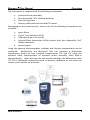
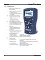
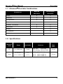
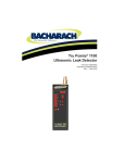
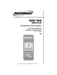
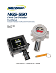
Carbon Monoxide Analyzer Configuration and Operation Manual Instruction 0019-9370 Rev 1 October 2014 Product Leadership • Training • Service • Reliability Monoxor Plus Manual WARRANTY POLICY Bacharach, Inc. (Bacharach) warrants to the buyer that this product will be free from material defects, free from manufacturing defects, and will conform substantially to Bacharach’s applicable specifications at the time of delivery. Bacharach’s liability and the buyer’s remedy under this warranty are limited to the repair or replacement, at Bacharach’s option, of this product or parts thereof returned to Bacharach and shown to Bacharach’s reasonable satisfaction to have been defective; provided that written notice of the defect is given by buyer to Bacharach within two (2) years after the date of delivery of this Product by Bacharach. Bacharach warrants to the buyer that Bacharach will convey good title to this product. Bacharach’s liability and the buyer’s remedy under this warranty of title are limited to: the removal of any title defects or, at the election of Bacharach, the replacement of this product or parts thereof that are defective in title. The foregoing warranties are exclusive and are given and accepted in lieu of (I) any and all other warranties, express or implied, including without limitation the implied warranties of merchantability and fitness for a particular purpose: and (II) any obligation, liability, right, claim or remedy in contract or tort, whether or not arising from Bacharach’s negligence, actual or implied. The remedies of the buyer shall be limited to those provided herein to the exclusion of any and all other remedies including, without limitation incidental or consequential damages. No agreement varying or extending the foregoing warranties, remedies or this limitation will be binding upon Bacharach unless in writing and signed by a duly authorized officer of Bacharach. Register your warranty by visiting www.MyBacharach.com ii 0019-9370 Rev 1 Monoxor Plus Manual NOTICE Product improvements and enhancements are continuous; therefore the specifications and information contained in this document may change without notice. Bacharach, Inc. shall not be liable for errors contained herein or for incidental or consequential damages in connection with the furnishing, performance, or use of this material. No part of this document may be photocopied, reproduced, or translated to another language without the prior written consent of Bacharach, Inc. Copyright © 2014, Bacharach, Inc., all rights reserved. BACHARACH, Fyrite, True Spot, Monoxor, and B-SMART are registered trademarks of Bacharach, Inc. All other trademarks, trade names, service marks and logos referenced herein belong to their respective companies. 0019-9370 Rev 1 iii Monoxor Plus Manual iv 0019-9370 Rev 1 Monoxor Plus Manual Table of Contents Table of Contents Section 1. 1.1. 1.2. 1.3. 1.4. 1.5. 1.6. 1.7. 1.8. Introduction ............................................................................................ 1 Conventions............................................................................................. 1 Safety ....................................................................................................... 1 Product Overview .................................................................................... 2 Components ............................................................................................ 6 Features ................................................................................................... 8 Monoxor Plus Sales Combinations ........................................................ 9 Specifications........................................................................................... 9 Section 2. 2.1. 2.2. 2.3. 2.4. Overview .................................................................................... 1 Setup ........................................................................................ 11 Connecting the Probe ............................................................................ 11 Front Panel Buttons............................................................................... 12 Power Options ....................................................................................... 13 Turning On the Monoxor Plus ............................................................. 14 Section 3. Configuration ........................................................................... 15 3.1. Menu Structure Overview ..................................................................... 15 3.2. The Warm-up Sequence ........................................................................ 15 3.3. Main Menu ............................................................................................ 16 3.4. Ambient CO Menu ................................................................................. 17 3.5. Differential Temperature Menu ............................................................ 18 3.6. Memory Options Menu ......................................................................... 19 3.7. Setup Menu ........................................................................................... 20 3.8. Calibration Menu................................................................................... 28 3.9. Diagnostics Menu .................................................................................. 29 3.10. Status Menu ........................................................................................ 30 Section 4. 4.1. 4.2. 4.3. 4.4. 4.5. 4.6. 4.7. 4.8. 4.9. Operation ................................................................................. 31 Overview ............................................................................................... 31 Taking a Gas Sample .............................................................................. 31 The RUN and Hold Screens .................................................................... 32 CO Trending Graph ................................................................................ 33 Ending a Test ......................................................................................... 33 Taking Differential Temperature Measurements .................................. 34 Timed Ambient CO Testing.................................................................... 35 Printing Using the Optional IrDA Printer ............................................... 36 Turning Off the Analyzer ....................................................................... 38 0019-9370 Rev 1 v Monoxor Plus Manual Table of Contents 4.10. PC Interface and Fyrite User Software .............................................. 38 Section 5. Calibration and Maintenance .................................................. 39 5.1. Serviceability ......................................................................................... 39 5.2. Cleaning the Probe ................................................................................ 39 5.2.1. Equipment Required ................................................................. 40 5.2.2. Procedure ................................................................................. 40 5.3. Filter Replacement ................................................................................ 41 5.4. CO Sensor Replacement ........................................................................ 42 5.4.1. Accessing the CO Sensor ........................................................... 42 5.4.2. Material Required (As Needed) ................................................ 42 5.4.3. CO Sensor Replacement Procedure .......................................... 43 5.4.4. B-SMART CO Sensor Replacement.......................................... 43 5.5. Temperature Calibration ....................................................................... 44 5.5.1. Materials Required ................................................................... 44 5.5.2. Temperature Calibration Procedure ......................................... 44 5.6. CO Sensor Calibration............................................................................ 46 5.6.1. Materials Required ................................................................... 46 5.6.2. CO Manual Zero Procedure ...................................................... 46 5.6.3. CO Sensor Span Procedure ....................................................... 47 5.7. T-Ref Sensor Calibration ........................................................................ 48 Section 6. 6.1. 6.2. 6.3. 6.4. 6.5. Troubleshooting....................................................................... 49 Error and Warning Messages ................................................................ 49 Replacement Parts ................................................................................ 50 Accessories ............................................................................................ 50 Instrument Identification ...................................................................... 51 Service Centers ...................................................................................... 51 Declaration of Conformity ................................................................................. 53 ∇ ∇ ∇ vi 0019-9370 Rev 1 Monoxor Plus Manual Section 1. Overview Overview 1.1. Introduction Thank you for investing in a Bacharach Monoxor Plus carbon monoxide (CO) analyzer. To assure proper use and operator safety, please read the contents of this manual for important information on the operation and maintenance of the analyzer. 1.2. Conventions WARNING: A warning statement denotes a potential hazard associated with the use of this equipment. Failure to follow this information could result in serious personal injury or death. CAUTION: A caution statement indicates a potentially hazardous situation which, if not avoided, may result in minor or moderate injury. Caution statements may also be used to alert against unsafe practices. IMPORTANT: An important statement provides emphasis of an important feature, operation, etc. Failure to follow this information could void your warranty, result in improper operation, or cause equipment damage. NOTE: A note statement provides emphasis of a feature, operation, practice, etc. 1.3. Safety WARNING: This analyzer is not intended to be used as a safety device. WARNING: When testing an appliance, a full visual inspection of the appliance should be performed to ensure its safe operation. CAUTION: This analyzer is not intended to be used on a continuous basis. 0019-9370 Rev 1 1 Monoxor Plus Manual Overview CAUTION: Do not store instrument or its sensors with solvents or products that contain solvents. CAUTION: Except for sensor and battery replacement, this analyzer should only be opened and/or serviced by authorized Bacharach personnel. Failure to comply may void the warranty. HAZARDOUS AREA WARNING: This instrument has not been designed to be intrinsically safe for use in areas classified as hazardous locations. For your safety, DO NOT use it in hazardous (classified) locations. CAUTION: Do not use flammable or combustible substances (like carburetor fluid used for cleaning the probe) near an open flame. CAUTION: When the instrument is used in an inefficient oil-fueled appliance where there is a high emission of soot, the probe’s sample filter may become clogged. Before every use check the filter to confirm it is clean or replace it with a new filter. To prevent soot intake and a clogged filter, a smoke test should be performed before operating under such conditions. This ensures that the furnace or boiler is burning at a level appropriate for the use of this instrument. 1.4. Product Overview The Monoxor Plus is a portable hand-held carbon monoxide (CO) analyzer for use in residential and light commercial applications. It is intended to be used by: • • HVAC contractors home inspectors • • maintenance personnel safety inspectors to detect and display concentrations of CO gas between 0 and 2000 ppm. The analyzer is capable of testing for CO in both ambient room air and in the fluegas stream of fossil-fuel fired furnaces and boilers. Using the optional appliance kit, you can measure CO levels emitted from fossil-fuel-based appliances such as gas stoves and gas fireplaces. 2 0019-9370 Rev 1 Monoxor Plus Manual Overview The analyzer detects and displays the presence of CO by first drawing in a gas sample from the area being tested by the analyzer’s built-in motorized pump. The gas sample is next directed into a sensor chamber where the sample is analyzed for the presence of CO. If CO is detected, the CO ppm level is given on the analyzer’s main display. A trending screen (accessible from the RUN screen by using the right or left arrow key) shows dynamic CO levels graphed 0019-9370 Rev 1 3 Overview Monoxor Plus Manual over a programmable time period (from 30 seconds to 15 minutes). In addition to the visual notifications, you can set a CO alarm limit, above which an audible alarm buzzer will beep repeatedly. An audible alarm with a slower beep frequency occurs when the batteries are low. A backlight enables the operator to read the display in dimly-lit areas. The displays and menus are available in multiple languages (English, French and Spanish). A permanent record of the detected CO level, along with the current time and date, can be made by using the optional wireless IrDA printer. Test records can also be saved in memory. An ambient CO feature takes approximately 15 minutes to complete and provides a minute-by-minute snapshot of CO readings, as well as a “Max CO” value that represents the highest CO reading measured during the entire test. Results can be saved to memory and/or printed. Use the optional CO Appliance Kit (P/N 0024-8555) to perform an ambient CO measurement if required. A calibration reminder can be set to occur every 6, 8, 10, 12, or 15 months after the last calibration. (Select “Never” to disable this feature.) Regular calibration periods of 6 months to 1 year are recommended. The calibration reminder value sets a time period after which the analyzer displays a calibration reminder message during warm-up. To avoid the need for manual CO sensor calibrations, the B-Smart® Sensor program is supported with the Monoxor Plus. After enrolling in the program, pre-calibrated replacement B-Smart® CO sensors are shipped at predetermined intervals of your choice. • • • Choose a program start date that best suites your needs. Receive a pre-calibrated B-Smart® sensor. Return your old sensor in a returnable, pre-labeled container. Benefits include no downtime, self calibration, convenience, and cost savings. For additional information about the B-Smart® Calibration Program, contact Bacharach at 1-800-736-4666 or email [email protected]. A programmable inactivity timeout causes the analyzer to initiate shutdown mode if no key presses occur for the specified time period. If the analyzer initiates automatic shutdown or is turned OFF manually while a high level of CO is still present within the unit, the automatic CO purge feature forces the analyzer’s pump to remain on until the detected CO level drops below 50 ppm. 4 0019-9370 Rev 1 Monoxor Plus Manual Overview The instrument is supplied with the following components: • • • • probe and hose assembly four disposable “AA” alkaline batteries hard carrying case factory-calibrated and installed CO sensor. Depending on the model and kit, some or all of the following components are included: • • • • • spare filters Fyrite User Software (FUS) USB cable (type A to mini B) Infrared Data Association (IrDA) printer with four disposable “AA” alkaline batteries printer paper. Using the optional thermocouples, ambient and flue gas temperatures can be measured. Additionally, the Monoxor® Plus can calculate a differential temperature based on two sampled temperatures (T1 and T2) using the optional stack thermocouple or optional probe assembly (with built-in thermocouple). After you take the two sample readings, the differential value (T1-T2) is calculated, optionally saved in memory, displayed on the main run screen, and is shown on printouts. 0019-9370 Rev 1 5 Overview Monoxor Plus Manual 1.5. Components 6 0019-9370 Rev 1 Monoxor Plus Manual 0019-9370 Rev 1 Overview 7 Overview Monoxor Plus Manual 1.6. Features • • • • • • 8 Sensors (pp 9, 17, 18, 32, 42) o Field-replaceable electrochemical sensor (B-Smart CO) o Temperature measurement using a Type K thermocouple (with probe assembly 19-7111) Power (pp 10, 13) o 4 AA alkaline batteries (included) o 4 AA lithium batteries o 4 AA rechargeable batteries (externally charged) o Low battery warning Testing Features (pp 17, 19, 28, 29, 30, 31) o Complete test results (10 sets) can be stored, recalled, displayed, and printed o Time and date stamping of test results o Differential temperature o Secure calibration function (password protected) o Auto power-off feature with sensor purge feature o Status and diagnostic menus o Ambient CO User Customizations (p 20) o Multi-language interface o Auto/Manual zero functions for the CO sensor o Customized user information (3 lines of 20 characters) o Customized logo on printouts (192 x 384 pixels) o Temperature unit selection Hardware (pp 6, 11, 32, 38) o Probe/hose assembly for gas transport o Sample pump to provide gas sample delivery o Backlit monochrome graphic LCD o Hard carrying case o USB 2.0 (mini-B connection) for PC interface and communications PC Interface (p 38) o USB cable (Type A to Mini B) o Fyrite User Software (FUS) (Windows compatible) o Updates 0019-9370 Rev 1 Monoxor Plus Manual Overview 1.7. Monoxor Plus Sales Combinations Basic Kit 0019-8117 Reporting Kit 0019-8118 Probe X X Batteries X X Temperature X X Manual X X B-Smart CO Sensor X X Hard Case X X Components Printer X PC Software X USB Cable X 1.8. Specifications Measure -ment Range Resolution Accuracy Response Time (T90) CO 0 to 2000 ppm 1 ppm ±10 ppm (0 to 200) ±5% reading (201 to 2000) < 40 sec Temp -20° to 650° C (-4° to 1202° F) 1° C (1° F) ±2° C (0° to 124° C) ±3° C (125° to 249° C) ±4° C (250° to 400° C) < 50 sec 0019-9370 Rev 1 9 Monoxor Plus Manual Overview Specification Temperature Description Storage: Operation: Reference: -20° to 50° C 0° to 20° C -5° to 45° C 20° ± 2° C ( -4° to 122° F) (32° to 68° F ) optimal (23° to 113° F) (68° ± 4° F) Humidity Storage: Operation: Reference: 15 to 90% RH, non-condensing 15 to 95% RH, non-condensing 45 ± 10% RH, non-condensing Pressure 1 atmosphere ± 10% Weight 16 ounces (454 g) with batteries Dimensions 8.0” x 3.6” x 2.3” (20.3 cm x 9.1 cm x 5.8 cm) (H x W x D) Warm-up Time Minimum = 30 seconds; Maximum = 60 seconds Gas Sample Flow Rate 300 to 700 cc/min Sensors CO: Temp: Electrochemical (P/N: 0024-7265) K-Type thermocouple Product Approvals and Regulatory Compliance EN50270: Case Construction High impact ABS plastic with co-molded rubber. Optional protective rubber boot with molded-in magnets. Display Monochrome with backlight USB Connector Mini B (USB 2.0) Memory 10 locations for storing test results IrDA Port Protocol: Baud Rate: (CE Mark) EMC tested in accordance with European Directive 2004/108/EC . RoHS Compliance Power Supply Options IrDA-SIR 9600 Data Bits: 8 Parity: None Stop Bits: 1 Type: Disposable Alkaline (Included) Duration: 15 hours min, continuous max draw Batteries (4 AA) Type: Disposable Lithium Duration: 20 hours, continuous max draw Type: Rechargeable Duration: 8 hours, continuous max draw ∇ ∇ ∇ 10 0019-9370 Rev 1 Monoxor Plus Manual Section 2. Setup Setup 2.1. Connecting the Probe A rigid stainless steel probe with handle is connected to a flexible hose with an integral water trap/filter and is used to draw a gas sample into the analyzer from the room, grilles, diffusers, and furnace flues. 1. 2. 3. Inspect the flexible hose for cracks. If a hose is defective, replace the entire probe assembly. Before using the analyzer, check that the water trap/filter is clean and dry. If necessary, dry out the trap and replace the filter element. Push the probe’s “sample gas” tubing onto the GAS inlet connector. 0019-9370 Rev 1 11 Monoxor Plus Manual Setup 2.2. Front Panel Buttons Button Description • • • • • • • • UP (), DOWN (), LEFT (), and RIGHT () arrows are context-specific navigation buttons for the menus. UP () and DOWN () arrow buttons scroll to menu options that are hidden from view (when a side scroll bar is displayed indicating additional information). UP () and DOWN () arrow buttons cause the displayed value to increase or decrease accordingly. LEFT () and RIGHT () arrow buttons jump to the top and bottom of lists, respectively. LEFT () and RIGHT () arrow buttons position the active cursor on specific elements of a value to be changed. LEFT () and RIGHT () arrow buttons display the CO Trending screen from the Run/Hold screen. • The ENTER button. Performs the action selected. • While in the HOLD screen, turns the sample pump on, displays the RUN screen, and begins a test. While in the RUN screen, turns the sample pump off, displays the HOLD screen and the last set of data. Displays the HOLD screen while pressing it from most menus. Returns the display to the HOLD screen while pressing it during the shutdown sequence. • • • 12 Powers the analyzer ON and OFF. Hold this button down for at least 2 seconds to turn the power OFF. Toggles the backlight ON and OFF while the analyzer is turned ON. • The ESC button cancels most operations and displays the previous screen. • Pressing function keys accepts the corresponding function defined above that key at the bottom of the display (for example, PRINT, SAVE, MENU, etc.). 0019-9370 Rev 1 Monoxor Plus Manual Setup 2.3. Power Options Power options include: • Disposable AA alkaline batteries (included) • Disposable AA lithium (Li) batteries • Externally charged rechargeable NiMH batteries. Check the Monoxor Plus for sufficient power prior to each use. Replace the batteries if the low (or replace) battery symbol appears in the upper right corner of the Monoxor Plus screen. Batteries (4 AA, Fresh or Fully Charged) Estimated Life Span in Hours (Continuous, Pump On) Alkaline (disposable) 15 hours Lithium (disposable) 20 hours Rechargeable 8 hours Replace batteries as follows. 1. Remove the battery cover from the back of analyzer. 2. If old batteries are installed, remove them and properly discard them. 3. Observing the polarity markings inside the battery compartment, install four ‘AA’ disposable (alkaline or lithium) batteries or four fullycharged (externally charged) AA rechargeable NiMH batteries. 4. Replace the battery cover. NOTE: The Monoxor Plus does NOT charge rechargeable batteries. NOTE: The Monoxor Plus sounds a series of beeps to indicate that the batteries need to be replaced. 0019-9370 Rev 1 13 Monoxor Plus Manual Setup NOTE: A Set Clock error message will be displayed if the instrument is without power for an extended period of time. 2.4. Turning On the Monoxor Plus To turn on the Monoxor Plus, press the PWR button. NOTE: After turning on the Monoxor Plus, it performs a warm-up procedure which includes an auto-zero procedure (when in Auto Zero mode) for the sensors (see pages 15 and 26). For this reason, be sure to turn on the Monoxor Plus in a clean air environment. When the analyzer is in CO Manual mode, the analyzer will indicate the background CO during startup. ∇ ∇ ∇ 14 0019-9370 Rev 1 Monoxor Plus Manual Section 3. Configuration Configuration 3.1. Menu Structure Overview Menus and the items contained within them are described in a top-down fashion, starting from the startup screens and working sequentially through the menus and menu items. 3.2. The Warm-up Sequence Boot Screens Description Splash screen shows the Bacharach logo with version, model number, and serial number information. This screen is displayed for approximately 3 seconds. A warm-up screen is displayed during which the instrument is purged and initialized. The current zero setting for the CO sensor (Auto-Zero or Manual Zero) is displayed briefly, followed by a countdown timer during initialization (see page 26 and page 46). If any errors are detected during warm-up, the corresponding error messages are displayed, after which the user presses F2 to go to the Menu, or presses RUN/HOLD to go to the Hold screen. (See page 49 for a list of error messages.) 0019-9370 Rev 1 15 Monoxor Plus Manual Configuration 3.3. Main Menu Display the Main Menu by pressing the F2 key. Note that features and items displayed in menus are model dependent. Your screens may vary. Main Menu Function Access the Ambient CO Test Menu (see page 17) • • • Initiate a 15-minute CO test Get reading every minute and max CO reading Print/Save 16 readings and max CO Access the Differential Temperature Menu (see page 18) • • • Display current temperature reading. Display differential temperature readings Save differential temperature information Access the Memory Options Menu (see page 19). • • Access previously saved test results Delete all previously saved test results Access the Setup Menu (see page 20). • • • Edit/view instrument preference Edit/view system parameters Edit/view test parameters Access the Calibration Password Screen and the Calibration Menu (see page 28). • Calibrate sensors Access the Diagnostics Menu (see page 29). • • View “run” meters and system diagnostic values Fresh air diagnostics Access the Device Status Menu (see page 30). • 16 Access the software date, model number, serial number, and version information 0019-9370 Rev 1 Monoxor Plus Manual Configuration 3.4. Ambient CO Menu Ambient CO Function Access the Ambient CO Menu. When initiated, the Ambient CO feature monitors CO values continuously and captures a reading every minute for 15 minutes (a total of 16 readings from t0 to t15). Press ENTER to initiate the Ambient CO test. This begins a 15-minute test cycle, during which a status screen is displayed. It shows the starting ambient CO value, the current CO value, and the elapsed time into the test. NOTE: Press the F2 key to cancel a test in progress. After the test is complete, the Ambient CO Summary screen is displayed. This is a scrollable window that shows the 16 CO “snapshot” readings, as well as the maximum CO reading that was sampled during the entire test. NOTE: The Max CO Reading is the highest sampled CO reading – even if the reading was taken in between one of the sample “snapshot” readings. 0019-9370 Rev 1 17 Monoxor Plus Manual Configuration Ambient CO Function The test results can be printed by pressing F1 and saved to memory (with a time and date stamp) by pressing F3. Press F2 to return to the menu. NOTE: Any over-range CO values (e.g., CO > 2000 ppm) are displayed as “xxx”. 3.5. Differential Temperature Menu Diff Temp Function The Diff Temp option is used to calculate a differential temperature based on two sampled temperatures. When this option is first selected, the current temperature (Temp) is displayed. Values for T1 and T2 will show no readings until they are saved by the operator, after which a differential value (T1-T2) will also be displayed. With temperature #1 (T1) selected, position the thermocouple in the target location, and wait for the temperature reading (Temp) to stabilize. Press the SAVE button to temporarily store the T1 value. Repeat these steps for the temperature #2 (T2). After saving both values, the “T1-T2” differential temperature will be displayed. At this point, you may press SAVE again to save the differential temperature value to memory so that it can be retrieved and/or printed later. Note that a negative differential value will be displayed if T1<T2. 18 0019-9370 Rev 1 Monoxor Plus Manual Configuration NOTE: The Differential Temperature feature requires the use of the optional thermocouple (P/N: 0104-1797) or the optional probe assembly (P/N: 0019-7111). 3.6. Memory Options Menu Memory Options Function Access the Memory Directory. This directory contains a numbered list of saved tests (starting at “1”) to a maximum of 10 test records. “NO DATA” is displayed if no tests were saved since the last time that memory was cleared. A “Memory Full” th message is displayed if you try to save an 11 test. To view saved data, use the UP () and DOWN () arrow buttons to highlight the desired test from the list. Press the ENTER button to display the saved data. Prompts user before clearing all saved tests from memory. Selecting NO returns the display to the Memory Options menu. Selecting YES clears the memory and displays the Memory Cleared message. 0019-9370 Rev 1 19 Configuration Monoxor Plus Manual 3.7. Setup Menu Setup Menu Function Access Temperature Units (°C or °F) to be used by the instrument and for display and printing purposes. Use the UP () and DOWN () arrows buttons to highlight the desired choice. Press the ENTER button to use the selected temperature unit. Press ESC to quit without saving. The Clock option provides access to the clock setup function to set date and time. Use the LEFT () and RIGHT () arrow buttons to select the desired field to edit. Then use the UP () and DOWN () arrow buttons to change the values of the selected field. Press ENTER to save new date and time. Press ESC to quit without saving. NOTE: See DATE FORMAT option in SETUP MENU to select either MM/DD/YY format or DD/MM/YY format. NOTE: The presence of AM or PM after the time on the Set Clock display indicates 12-hour time format and MM/DD/YY date format. Similarly, the absence of AM or PM indicates 24-hour time format and the date is in DD/MM/YY format. 20 0019-9370 Rev 1 Monoxor Plus Manual Setup Menu Configuration Function The zoom options selects the size of the characters on the Run/Hold screen. Three options are Standard, 2x, and 3x. Options are shown below with their respective Run/Hold screens. Use the UP () and DOWN () arrow buttons to scroll through display items that don’t fit on the screen. Zoom Level Sample Run/Hold Screen 0019-9370 Rev 1 21 Configuration Setup Menu Monoxor Plus Manual Function Provides an interface for entering user identification Generally, the information used on printouts. Username fields contain the HVAC company and related information. NOTE: This data can be entered using the Fyrite User Software (FUS). Use the UP () and DOWN () arrow buttons to choose a row and press ENTER to begin editing the selected row. Then use the UP () and DOWN () arrow buttons to select the desired letter, number, or special character for the current text position. / ! @ # $ & * - ‘ <SPACE> a-z A-Z 0-9 Use the LEFT () and RIGHT () arrow buttons to move the cursor horizontally on the selected row and repeat the character selection process for each text position. When finished, press ENTER to save the row’s changes. Repeat for all 3 lines. Then select EDIT COMPLETE and press ENTER to finish. SELECT MODE EDITING MODE 22 0019-9370 Rev 1 Monoxor Plus Manual Setup Menu Configuration Function The Language Selection option allows the user to choose a language for all menus. Use the UP () and DOWN () arrow buttons to scroll through language options. Use ENTER to enable the selected language. Three languages are available: English, French, and Spanish. The button sound option is used to select whether or not the analyzer makes an audible sound every time a key is pressed. Select OFF to disable this feedback, or ON to enable this feedback. Then press ENTER to select, or ESC to discard changes. The CAL Reminder Period option sets a time period after which the analyzer displays a calibration reminder message during warm-up. Calibration reminders can be set to occur never, 6, 8, 10, 12, or 15 months after the last calibration. Select NEVER (the default setting) to disable this feature. When the preset period is exceeded the instrument will display the reminder, and how long since the sensor was last calibrated. If a calibration reminder is displayed, the operator can press the RUN/HOLD key to move to the RUN/HOLD Screen for normal operation. Regular calibration periods of 6 months to 1 year are recommended. Set the calibration reminder period as follows: 1. Use the UP () and DOWN () arrow buttons to select the desired time period. 2. Press ENTER to save the selection or ESC to revert to the previous setting. 0019-9370 Rev 1 23 Configuration Setup Menu Monoxor Plus Manual Function NOTE: The date and time settings must be correct to get accurate calibration reminders. Provides a list from which to select an inactivity (key press) timeout for automatic shutdown. If no key presses occur for the time specified, the Monoxor Plus initiates an automatic shutdown. Use the UP () and DOWN () arrow buttons to scroll through Inactivity Timeout options (None [default], 20, 30, or 60 minutes). Use the ENTER key to enable the selected timeout. 24 0019-9370 Rev 1 Monoxor Plus Manual Configuration Setup Menu Function Provides a list from which the user may chose a minimum purge duration time (minimum length of time that the pump continues to run) after shutdown is initiated. Use a longer Post-Purge Period if the Monoxor Plus has been exposed to high concentrations of CO gas. Use ENTER to enable the selected Post-Purge Period. “PURGING SENSORS” is displayed on the shutdown screen if a Post-Purge Period is enabled. Use the UP () and DOWN () arrow buttons to scroll through Post-purge Period options. The Date Format option provides a list from which the user may select the desired date format used by the instrument. • • MM/DD/YY (w/ 12-hour time format) DD/MM/YY (w/ 24-hour time format) Use the UP () and DOWN () arrow buttons to highlight the desired date format. Press ENTER to save new date format. Press ESC to quit without saving. 0019-9370 Rev 1 25 Monoxor Plus Manual Configuration Setup Menu Function Provides a list from which the user may select the desired method for zeroing the CO sensor. Auto-Zero happens automatically at warm-up. Manual zero is used to initiate the zeroing process whenever desired. Use the UP () and DOWN () arrow buttons to highlight the desired zeroing method. Press ENTER to save. Press ESC to quit without saving. CO AUTO ZERO CO MANUAL ZERO • • By default, the Monoxor Plus automatically zeroes all sensors on ambient air when the instrument is turned on. The Monoxor Plus can be set to perform and store a manual zero for the CO sensor. The instrument uses the stored value to indicate background CO values after warm-up instead of performing an auto-zero on the background gas. 26 0019-9370 Rev 1 Monoxor Plus Manual Setup Menu Configuration Function The CO Alarm Limit option is used to enable and disable the alarm limit feature. If enabled (ON), an additional screen is displayed where you set the CO alarm setpoint. The alarm limit is selectable from 0 to 2000 ppm. Use the Up and Down arrow buttons to scroll to the desired alarm limit value then press ENTER. Note that scrolling wraps forward and backwards, so pressing the down arrow at 0 ppm wraps backwards to 2000. Similarly, pressing up arrow at 2000 ppm wraps forward to 0 ppm. When the CO Alarm Limit option is enabled, the builtin buzzer will sound if CO readings exceed the CO alarm limit that you defined. 0019-9370 Rev 1 27 Configuration Monoxor Plus Manual 3.8. Calibration Menu Calibration Menu Function Calibration is performed by applying known values and accessing the password-protected menu items. When the Calibration Menu is selected, the user must enter a 4-digit numeric security code in order to proceed to the calibration options. The default password is 1111. Use the UP () and DOWN () arrow buttons to scroll through numerals 0-9 until the desired numeral is reached. Press ENTER to advance to the next position of the password. Press ENTER after all four digits are set. Press ESC to return to the SETUP MENU. NOTE: The calibration password can be changed through the Fyrite User Software (FUS). Refer to Chapter 5 (page 39) for additional screens and calibration procedures. 28 0019-9370 Rev 1 Monoxor Plus Manual Configuration 3.9. Diagnostics Menu Diagnostics Menu Function Displays time metrics for pump use and total operation time. Displays information about the measurement sensors of the instrument. Displays fresh air diagnostics similar to the display at warm-up. After the warm-up countdown, any detected errors are displayed. Otherwise, a “Success” message is displayed. 0019-9370 Rev 1 29 Monoxor Plus Manual Configuration 3.10. Status Menu Status Menu Function This is the device status screen which displays information about the device. Some of the information displayed on this screen includes serial number, firmware version, model number, etc. ∇ ∇ ∇ 30 0019-9370 Rev 1 Monoxor Plus Manual Section 4. Operation Operation 4.1. Overview To operate the Monoxor Plus, you simply. . . • • • Turn the analyzer ON Wait for the unit to warm up Take a gas sample. Before beginning your test, verify the following: • • • • • menu items are properly configured the disposable filter is clean the probe is attached to the instrument the power is ON and sufficient (one of the following): o four new batteries (AA alkaline) o four new batteries (AA lithium) o four fully-charged AA rechargeable batteries the warm-up process has completed in fresh air without interruption or errors. 4.2. Taking a Gas Sample IMPORTANT: Important! If the CO channel is set up for Auto Zero (refer to Section 3.4.3), ensure that the analyzer will be sampling fresh air (containing no CO) when turned ON. Turn ON the analyzer by pressing the PWR button. Observe that when power is first applied, the software revision level is first displayed followed by a screen that counts down the warm-up period. The warm-up period is either 30 seconds or 60 seconds depending on the setting and sensor condition. Following warm-up (and an optional error screen), the Main Menu screen appears. If the probe is being used, insert the probe tip into the area to be sampled. Press the Run/Hold button once to display the HOLD screen (last values), and a second time to display the RUN screen (dynamic display of current CO level in ppm, temperature, and min/max CO values. 0019-9370 Rev 1 31 Operation Monoxor Plus Manual NOTE: If a sensor error was detected during warm-up, the CO Sensor Error Screen will be displayed. 4.3. The RUN and Hold Screens 32 0019-9370 Rev 1 Monoxor Plus Manual Operation NOTE: Use the left or right arrow buttons from the Run or Hold screen to view the CO trending graph. 4.4. CO Trending Graph A trending screen is accessible from the RUN or HOLD screen by using the right of left arrow keys. The CO Trending Screen shows dynamic CO levels graphed over a programmable time period. User-selectable time periods are: • • • • • 30 seconds 1 minute 3 minutes 5 minutes 15 minutes. The graph continues to sample CO gas while in RUN mode, showing the current PPM reading above the dynamic graph. Press the RUN/HOLD button (HOLD mode) to freeze the current graphical snap-shot. In HOLD mode, a pointer appears on the graph. This pointer can be moved along the graph using the left and right arrow keys. As you move the pointer left and right, the value of the CO at that point in the sampling is displayed at the top of the screen. 4.5. Ending a Test WARNING: Burn Hazard. Do not touch the probe after removing it from a flue. Allow the probe to cool before handling (about 5 minutes). After taking a gas sample, remove the probe and take the analyzer to an area containing fresh air. Allow the pump to run until the CO reading drops to near zero. 0019-9370 Rev 1 33 Monoxor Plus Manual Operation 4.6. Taking Differential Temperature Measurements In certain combustion applications, it may be desirable to have a differential temperature measurement. Use the Diff Temp menu and either the optional probe assembly with thermocouple (P/N 0019-7111), or one of the optional KType thermocouples (P/N 0104-1798 or P/N 0104-1797) to accomplish this task. The Monoxor Plus calculates the differential temperature based on two sampled temperatures (T1 and T2) which it reads from the optional probe assembly’s thermocouple (which is connected to the T-STACK connector of the instrument). After you take the two sample readings, the differential value (T1-T2) is calculated, optionally saved in memory, displayed on the main run screen, and is shown on printouts. Use the following procedure to perform a differential temperature measurement. 34 Step Example Procedure for Taking Differential Temperature Measurements 1 Attach the thermocouple plug of the optional probe assembly to the T-STACK connector on the bottom of the Monoxor Plus. 2 From the Main Menu, select the Diff Temp option. When this option is first selected, the current temperature (Temp) is displayed. Values for T1 and T2 will show no readings until they are saved by the operator, after which a differential value (T1-T2) will also be displayed. 3 With T1 highlighted, position the probe at desired location #1. 4 After a T1 temperature reading is displayed and stabilizes, press the F3 (SAVE) button to store the current T1 temperature reading. The T2 temperature reading is highlighted. 5 Move the probe to desired location #2. 6 After a T2 temperature reading is displayed and stabilizes, press the F3 (SAVE) button to store the current T2 temperature reading. 7 The temperature differential temperature (T1-T2) will be displayed. 0019-9370 Rev 1 Monoxor Plus Manual Operation Step Example Procedure for Taking Differential Temperature Measurements 8 At this point, you may press SAVE again to save the differential temperature value to memory so that it can be retrieved and/or printed later. 9 Carefully remove the probe assembly and allow it to cool. NOTE: A negative differential value will be displayed if T1<T2. 4.7. Timed Ambient CO Testing This procedure takes approximately 15 minutes to complete and provides a minute-by-minute snapshot of CO readings, as well as a “Max CO” value that represents the highest CO reading measured during the entire 15-minute test. Results can be saved to memory and/or printed. Use the optional CO Appliance Kit (P/N 0024-8555) and the following procedure to perform an ambient CO measurement. Step Example Procedure for Taking Ambient CO Measurements 1 Attach optional appliance kit probe (P/N 0024-8555) if required. 2 Turn on the Monoxor Plus in a fresh air environment and wait for initialization to complete. 3 Verify successful initialization (no errors). 4 Check battery status (see page 13). If battery life is questionable, replace the batteries, as the Ambient CO test takes approximately 15 minutes to complete. 5 Move instrument to target location to be tested. 6 Press F2 to display the Main Menu. 7 Use the down arrow to highlight Ambient CO Test and press the ENTER button. 8 Follow the on-screen instructions to initiate the test. Refer to page 17 for details on navigating the ambient CO test screens, viewing results, saving results to memory, and printing results. 0019-9370 Rev 1 35 Monoxor Plus Manual Operation 4.8. Printing Using the Optional IrDA Printer The instrument has the ability to store, recall (to the display), and print sets of time- and date-coded test records. The time and date are set through software menu selections. • 36 • Displaying stored records is done through the MEMORY DIRECTORY MENU. Press F1 to print displayed test records. Step Example Printing Procedure Using Optional IrDA Printer 1 Monoxor Plus should be turned on and displaying a screen with an F1 Print option. 2 Check for a sufficient supply of paper and batteries in the IrDA printer. 3 Turn on the printer. 4 Position the printer within 8 to 16 inches (20 to 41 cm) from the instrument and at no greater than a 60-degree angle. 5 Press F1 to print. 6 Turn off printer when complete. 0019-9370 Rev 1 Monoxor Plus Manual Operation IR Communications Settings: Baud Rate: Data Bits: Stop Bits: Parity: Protocol: Distance: Angle: 0019-9370 Rev 1 9600 8 1 None IRDA-SIR 8-16 in (20-41 cm) 60° maximum 37 Monoxor Plus Manual Operation The Monoxor Plus provides three lines of 20 characters for user information. This information will appear with test records when they are printed. User name and optional information are entered via software menu selections in the SETUP MENU or via the Fyrite User Software (FUS). In addition to the three lines of text, the Monoxor Plus can be setup to include a custom logo on printouts. Logos are loaded into the instrument using the Fyrite User Software (FUS). Logo size is limited to 192 x 384 pixels (height x width) and must be in one of the following formats: .BMP, .JPG, .PNG, or .TIFF. For best results, the logo should be saved in black and white. 4.9. Turning Off the Analyzer Turn OFF the analyzer by pressing the power button and holding for approximately 2 seconds. The analyzer will count down from 5 seconds before turning OFF. Pressing ENTER, however, will abort the count down and keep the analyzer ON. 4.10. PC Interface and Fyrite User Software A PC with Fyrite User Software (FUS) installed can set, edit, and transfer the following: • • • • • instrument time and date calibration password time meters B-SMART code user name • • • • instrument settings customer logo firmware updates language. ∇ ∇ ∇ 38 0019-9370 Rev 1 Calibration and Maintenance Section 5. Monoxor Plus Manual Calibration and Maintenance 5.1. Serviceability The instrument operator is able to easily replace the following components without the use of tools: • • • • • probe assembly probe filters batteries B-Smart CO sensor printer paper. Additionally, a technician, with the use of factory-provided instructions, can: • • perform basic diagnostics confirm proper operation before putting the unit back into service. Field calibration is also possible with the proper equipment. Refer to the calibration section for more information. 5.2. Cleaning the Probe The probe tube and gas sample hose will become dirty under normal use. NOTE: The filter element should prevent soot from reaching the analyzer’s internal components. If the probe is not kept clean, it could become clogged and restrict the flow of gas into the analyzer, resulting in incorrect test readings. NOTE: An analyzer that tests natural gas furnaces normally requires less frequent cleaning than an analyzer used for testing coal- or oil-fired furnaces. 0019-9370 Rev 1 39 Monoxor Plus Manual Calibration and Maintenance 5.2.1. Equipment Required • • • • Alcohol Aerosol Can of Automotive Carburetor Cleaner Clean Rag Source of Compressed Air (optional) CAUTION: Do not use flammable or combustible substances (like carburetor fluid used for cleaning the probe) near an open flame. 5.2.2. Procedure Step 1 Cleaning the Probe Remove gas sample hose from the disposable filter assembly. CAUTION: Carburetor cleaner damages plastic components. Take precautions not to spray cleaner onto the probe handle or analyzer. 40 2 Insert the plastic spray tube of the carburetor cleaner into the gas sample hose, and then liberally spray carburetor cleaner through the hose and out the probe tube. 3 After spraying, remove all the residual cleaner by repeatedly flushing the gas hose and probe tube with alcohol. 4 Wipe off the surfaces of the probe and tubing with a clean cloth. 5 Allow the parts to dry completely. If available, blow compressed air through the probe to expedite the drying process. 6 Reconnect gas sample hose to the disposable filter assembly. 0019-9370 Rev 1 Monoxor Plus Manual Calibration and Maintenance 5.3. Filter Replacement 0019-9370 Rev 1 41 Calibration and Maintenance Monoxor Plus Manual 5.4. CO Sensor Replacement 5.4.1. Accessing the CO Sensor 5.4.2. Material Required (As Needed) • 42 CO Sensor (P/N 0024-7265) or B-Smart sensor (P/N 0024-1467). 0019-9370 Rev 1 Monoxor Plus Manual Calibration and Maintenance 5.4.3. CO Sensor Replacement Procedure Follow the procedure below for CO sensor replacement. Step CO Sensor Replacement Procedure 1 Remove battery door and the connector tubing from the CO sensor. 2 Remove CO cap by twisting counter clockwise. 3 Gently pull CO sensor out of its socket. 4 Properly dispose of the old CO sensor. 5 Plug new CO sensor into its socket. 6 Install the CO cap by aligning it toward the “open” position (12 o’clock) as shown in the diagram below, then twisting the cap clockwise approximately 40° to the "closed" position (2 o’clock). 7 Reattach tubing. 8 Calibrate the CO sensor using either the standard calibration procedure or the B-SMART procedure 5.4.4. B-SMART CO Sensor Replacement Step B-SMART CO Sensor Replacement 1 Enter the CALIBRATION MENU. Note that this requires password validation (see page 28). 2 Use the UP () and DOWN () arrow buttons to select B-Smart. Press ENTER to display the B-Smart code screen. 3 Use the UP () and DOWN () arrow buttons to enter the 10-digit alphanumeric code supplied with the pre-calibrated B-SMART sensor. Use the LEFT () and RIGHT () arrow buttons to move the cursor across the screen. Press ENTER. 0019-9370 Rev 1 43 Calibration and Maintenance Monoxor Plus Manual B-SMART CO Sensor Replacement Step NOTE: If the correct code was entered, the analyzer accepts it and returns to the CALIBRATION MENU. If an incorrect code was entered, the screen will display "Invalid Code." Check to make sure the correct code has been entered. If problem persists, contact your nearest Bacharach Service Provider. NOTE: B-SMART codes can be entered through the Fyrite User Software (FUS). NOTE: Installing a B-SMART sensor forces the instrument to perform a zero function (either manual or automatic). NOTE: Bacharach offers a convenient Exchange Program (where available) that allows the customer to regularly receive pre-calibrated replacement sensors that include a code that can be entered into the analyzer for a quick convenient setup. Contact Bacharach customer service for more details about this program. 5.5. Temperature Calibration This procedure first zeroes and then spans the temperature channel to known temperature values. The use of an electronic thermocouple simulator is the preferred method of producing the desired calibration temperatures. Alternatively, ice and boiling water baths can be used. 5.5.1. Materials Required • • Thermocouple simulator (K-type) Range: 0 to 600° F (-18 to 316° F) Accuracy: ± 0.5° F (± 0.3° C) (Alternatively) ice water, boiling water, thermometer 5.5.2. Temperature Calibration Procedure 44 0019-9370 Rev 1 Monoxor Plus Manual Calibration and Maintenance Step Temperature Calibration Procedure 1 Plug the simulator into the TEMP connector located at the bottom of the analyzer. Alternatively: Plug the probe's thermocouple into the TEMP connector located at the bottom of the analyzer if using optional probe with thermocouple accessory (P/N 0024-7111). IMPORTANT: DO NOT attach the probe's gas hose to the analyzer's GAS port; otherwise water will be drawn into the analyzer! 2 If not already done, turn ON the analyzer and display the CALIBRATION Menu. Note that this requires password validation (see page 28). 3 Use the UP () and DOWN () arrow buttons to highlight Temperature, and then press ENTER to display the CALIBRATE TS-ZERO screen. "Measured" is the current temperature reading. "Applied" is a known temperature that will be applied for calibration purposes. 4 Set thermocouple simulator to 32° F (0° C), and then use the UP (), DOWN (), LEFT (), and RIGHT () arrow buttons to enter an Applied value that exactly equals the setting of the simulator. Alternatively: Submerge probe tip into an ice-water bath with a thermometer, wait several minutes, and then use the UP () and DOWN () arrow buttons to enter an Applied value that exactly equals the thermometer reading. NOTE: The calibration range is from 32 to 41° F (0 to 5° C). An attempt to calibrate outside this range will cause the message “Applied Value High" (or Low) to appear at the bottom of the screen. 5 Wait until the Measured reading stabilizes, and then press ENTER to calibrate the TS-Zero Measured value to that of the Applied value, after which the message “Good Calibration” should briefly appear followed by the CALIBRATE TS-SPAN screen. 6 Set thermocouple simulator to 572° F (300° C), and then use the UP (), DOWN (), LEFT (), and RIGHT () arrow buttons to enter an Applied 0019-9370 Rev 1 45 Calibration and Maintenance Step Monoxor Plus Manual Temperature Calibration Procedure value that exactly equals the setting of the simulator. Alternatively: Submerge probe tip into a container of boiling water with a thermometer, wait several minutes, and then use the arrow buttons to enter an Applied value that exactly equals the thermometer reading. NOTE: The calibration range is from 175 to 625° F (80 to 329° C). An attempt to calibrate outside this range will cause the message “Applied Value High” (or Low) to appear at the bottom of the screen. 7 Wait until the Measured reading stabilizes, and then press ENTER to calibrate the TS-Span Measured value to that of the “Applied” value, after which the message “Good Calibration” should briefly appear followed by the CALIBRATION menu being re-displayed. 5.6. CO Sensor Calibration 5.6.1. Materials Required • • Calibration kit, P/N 0024-7059 Gas cylinder: 500 ppm CO in air, P/N 0024-0492 5.6.2. CO Manual Zero Procedure The CO zeroing process is done automatically during warm-up or manually using the manual zero feature (see page 26). To perform a manual zero, follow the steps below. If your instrument is configured for CO auto zero, then skip this CO manual zero procedure and go to the CO Sensor Span procedure that follows. Step Manual CO Zero Procedure 1 If not already done, turn ON the analyzer and display the Main Menu screen. 2 Use the UP () and DOWN () arrow buttons to select the SETUP menu and press ENTER. 3 From the Setup Menu, use the UP () and DOWN () arrow buttons to select the CO Zero Setting parameter then press ENTER. 46 0019-9370 Rev 1 Monoxor Plus Manual Calibration and Maintenance Step Manual CO Zero Procedure 4 From the CO Zero Setting screen, use the DOWN () arrow button to select the Manual Zero option then press ENTER. A reminder screen to place the instrument in fresh air is displayed. 5 Press ENTER and wait for the manual zero to complete. 5.6.3. CO Sensor Span Procedure Step CO Span Procedure 1 From the Calibration Menu (see page 28), use the UP () and DOWN () arrow buttons to highlight CO, and then press ENTER to display the CALIBRATE CO screen. This requires password validation (see page 28). “Measured” is the current CO reading, while “Applied” is a known CO level that will be applied for calibration purposes. 2 Use the UP (), DOWN (), LEFT (), and RIGHT () arrow buttons to enter an Applied value that exactly equals the concentration stamped on the CO cylinder. NOTE: Bacharach recommends using a 500 ppm calibration gas, however the calibration range is from 20 to 1,000 ppm. An attempt to calibrate outside this range will cause the message “Applied Value High” (or Low) to appear at the bottom of the screen. 0019-9370 Rev 1 47 Monoxor Plus Manual Calibration and Maintenance Step CO Span Procedure 3 Attach a 500 ppm CO cylinder to the regulator and connect calibration kit components as shown below. Apply 500 ppm carbon monoxide in an air balance calibration gas. 4 Wait until the Measured reading stabilizes and then press ENTER. The message “Good Calibration” should briefly appear. If the sensor’s output is low, but still usable, then the message “Good Calibration WARNING Low Sensor” will appear. The sensor will now be marked as being Low in the Warm-up screen. If the sensor’s output is too low to be usable, then the message “Bad Calibration Sensor End of Life, Entry Not Saved” will appear. 5 Close the regulator and remove the CO cylinder. 5.7. T-Ref Sensor Calibration The T-Ref sensor is located inside the instrument. Calibration is done at the factory and should not need to be done in the field. ∇ ∇ ∇ 48 0019-9370 Rev 1 Monoxor Plus Manual Section 6. Troubleshooting Troubleshooting 6.1. Error and Warning Messages Message Description Low Sensor CO CO sensor output was low but still usable. Sensor may need to be replaced in the near future. Low Battery Battery voltage is low. Replace the batteries. Applied Value High/Low An attempt was made to calibrate a sensor outside its range— either above (High) or below (Low) the acceptable range. Warm-up Sensor Error • CO sensor was not zeroed at warm-up because of high output. Run instrument on fresh air then restart instrument to re-zero sensor. If the message persists, the CO sensor may need to be replaced. • Temperature sensors are measuring temperature outside the range of -4° to 212° F at warm-up. Make sure that the thermocouple is sampling ambient room air within the temperature range at warm-up. • Messages will indicate which sensors are in error. Set Clock Time and date values need to be set in the instrument. XXX Occurs in the number fields of sensors that have achieved overrange condition. *** Occurs in the number fields of sensors. Replaces in-error sensor values and any calculated values that depend on those sensor values. --- Occurs in the number fields of sensors and indicates that values were not calculated. Beeping Slow beep frequency: Fast beep frequency: Replace batteries warning. CO alarm is active and set. If a particular sensor is in error during warm-up, the instrument automatically displays the error. The instrument continues to operate with the sensor in error, however information dependent on the sensor in error is not displayed. NOTE: 0019-9370 Rev 1 49 Monoxor Plus Manual Troubleshooting 6.2. Replacement Parts Part Number Description 0204-0004 Battery, AA Alkaline (qty 1) 0024-7265 CO sensor, uncalibrated 0024-1467 B-Smart CO sensor 0019-7110 Replacement probe assembly with water trap 0019-3265 Replacement water trap for probe assembly 0024-7110 0007-1644 Replacement filter element for probe assembly 0024-7110 0024-1579 Replacement End Plate 0024-3073 Replacement Pump Assembly 0024-1620 Battery door/sensor cover 0024-1484 CO Sensor Cap 0024-1458 CO Sensor Base 0019-9370 Instruction manual 6.3. Accessories Part Number 50 Optional Accessory 0024-1400 IrDA printer 0024-1310 Printer paper, box of 5 rolls 0021-7006 True Spot Smoke Tester kit 0104-1798 Thermocouple (temperature, air), K-type (1 inch long) 0104-1797 Thermocouple (temperature, stack), K-type (10 feet long) 0024-7059 CO Calibration kit (no gas) 0024-0492 CO calibration gas, 500 ppm CO 0051-1994 CO calibration gas, 100 ppm CO 0024-1470 PC Software Installer CD 0104-4032 USB cable (A to Mini-B) 0024-1461 Boot , rubber 0024-1505 NOx filter kit 0024-1504 NOx filter 0024-8555 Optional Appliance Kit for Ambient CO Test 0019-7111 Optional probe assembly with thermocouple 0019-9370 Rev 1 Monoxor Plus Manual Troubleshooting 6.4. Instrument Identification A label on the back of the instrument provides the following information that is useful for service and troubleshooting. • • • • • manufacturer country of origin certification(s) part number serial number 6.5. Service Centers Replacement parts and service can be obtained by contacting one of the following Bacharach Service Centers. United States Bacharach, Inc. 621 Hunt Valley Circle New Kensington, PA 15068 Phone: 724-334-5051 Fax: 724-334-5723 Email: [email protected] Canada Bacharach of Canada, Inc. 20 Amber Street Unit #7 Markham, Ontario L3R 5P4 Canada Phone: 905-470-8985 Fax: 905-470-8963 Email: [email protected] ∇ ∇ ∇ 0019-9370 Rev 1 51 Monoxor Plus Manual 0019-9370 Rev 1 Troubleshooting 52 Monoxor Plus Manual Declaration of Conformity Declaration of Conformity The manufacturer of the products covered by this declaration: Bacharach, Inc. 621 Hunt Valley Circle New Kensington, PA 15068 Year conformity is declared: 2013 Product(s): CO Analyzer Model(s): Monoxor Plus The undersigned hereby declares that the above referenced product is in conformity with the provisions of the following standards and is in accordance with the following directive. Directive: 2004/108/EC EMC Directive Standard(s): EN 50270: 2006 Electromagnetic Compatibility (Immunity): Electrical Apparatus for the Detection and Measurement of Combustible Gases, Toxic Gases, or Oxygen Signature: Name: Title: Date: Doug Keeports President June 27, 2013 The technical documentation file required by this directive is maintained at the corporate headquarters of Bacharach, Inc. 0019-9370 Rev 1 53 Monoxor Plus Manual World Headquarters 621 Hunt Valley Circle, New Kensington, Pennsylvania 15068 Phone: 724-334-5000 • Toll Free: 1-800-736-4666 • Fax: 724-334-5001 Website: www.MyBacharach.com • E-mail: [email protected] 0019-9370 Rev 1 54