1
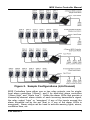
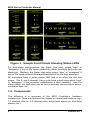
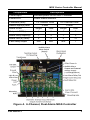
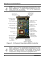
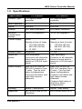
Multi-Channel Input
Single- and Dual-Alarm
Controllers
Installation and Operation Manual
Instruction 6709-9000
Revision 1 – October 25, 2012
Product Leadership • Training • Service • Reliability
MGS Series Controller Manual
WARRANTY POLICY
BACHARACH, INC. WARRANTS THIS INSTRUMENT, EXCLUDING SENSORS, TO BE
FREE FROM DEFECTS IN MATERIALS AND WORKMANSHIP FOR A PERIOD OF ONE
YEAR FROM THE DATE OF PURCHASE BY THE ORIGINAL OWNER. THE SENSORS
HAVE A WARRANTY PERIOD OF ONE YEAR FROM THE DATE OF PURCHASE. IF
THE PRODUCT SHOULD BECOME DEFECTIVE WITHIN THIS WARRANTY PERIOD,
WE WILL REPAIR OR REPLACE IT AT OUR DISCRETION.
THE WARRANTY STATUS MAY BE AFFECTED IF THE INSTRUMENT HAS NOT BEEN
USED AND MAINTAINED PER THE INSTRUCTIONS IN THIS MANUAL OR HAS BEEN
ABUSED, DAMAGED, OR MODIFIED IN ANY WAY. THIS INSTRUMENT IS ONLY TO BE
USED FOR PURPOSES STATED HEREIN. THE MANUFACTURER IS NOT LIABLE FOR
AUXILIARY INTERFACED EQUIPMENT OR CONSEQUENTIAL DAMAGE.
DUE TO ONGOING RESEARCH, DEVELOPMENT, AND PRODUCT TESTING, THE
MANUFACTURER RESERVES THE RIGHT TO CHANGE SPECIFICATIONS WITHOUT
NOTICE. THE INFORMATION CONTAINED HEREIN IS BASED ON DATA CONSIDERED
ACCURATE. HOWEVER, NO WARRANTY IS EXPRESSED OR IMPLIED REGARDING
THE ACCURACY OF THIS DATA.
ALL GOODS MUST BE SHIPPED TO THE MANUFACTURER BY PREPAID FREIGHT.
ALL RETURNED GOODS MUST BE PRE-AUTHORIZED BY OBTAINING A RETURN
MERCHANDISE AUTHORIZATION (RMA) NUMBER. CONTACT THE MANUFACTURER
FOR A NUMBER AND PROCEDURES REQUIRED FOR PRODUCT TRANSPORT.
SERVICE POLICY
BACHARACH, INC. MAINTAINS AN INSTRUMENT SERVICE FACILITY AT THE
FACTORY. SOME BACHARACH DISTRIBUTORS / AGENTS MAY ALSO HAVE REPAIR
FACILITIES, HOWEVER, BACHARACH ASSUMES NO LIABILITY FOR SERVICE
PERFORMED BY ANYONE OTHER THAN BACHARACH PERSONNEL. REPAIRS ARE
WARRANTED FOR 90 DAYS AFTER DATE OF SHIPMENT (SENSORS, PUMPS,
FILTERS AND BATTERIES HAVE INDIVIDUAL WARRANTIES). SHOULD YOUR
INSTRUMENT REQUIRE NON-WARRANTY REPAIR, YOU MAY CONTACT THE
DISTRIBUTOR FROM WHOM IT WAS PURCHASED OR YOU MAY CONTACT
BACHARACH DIRECTLY.
IF BACHARACH IS TO DO THE REPAIR WORK, SEND THE INSTRUMENT, PREPAID,
TO BACHARACH, INC. AT THE FOLLOWING ADDRESS.
BACHARACH, INC.
621 HUNT VALLEY CIRCLE
NEW KENSINGTON, PA 15068
ATTENTION: SERVICE DEPARTMENT
ALWAYS INCLUDE YOUR RMA #, ADDRESS, TELEPHONE NUMBER, CONTACT
NAME, SHIPPING/BILLING INFORMATION AND A DESCRIPTION OF THE DEFECT AS
YOU PERCEIVE IT. YOU WILL BE CONTACTED WITH A COST ESTIMATE FOR
EXPECTED REPAIRS PRIOR TO THE PERFORMANCE OF ANY SERVICE WORK. FOR
LIABILITY REASONS, BACHARACH HAS A POLICY OF PERFORMING ALL NEEDED
REPAIRS TO RESTORE THE INSTRUMENT TO FULL OPERATING CONDITION.
2
6709-9000 Rev 1
MGS Series Controller Manual
PRIOR TO SHIPPING EQUIPMENT TO BACHARACH, CONTACT OUR OFFICE FOR AN
RMA # (RETURNED MERCHANDISE AUTHORIZATION). ALL RETURNED GOODS
MUST BE ACCOMPANIED WITH AN RMA NUMBER.
PACK THE EQUIPMENT WELL (IN ITS ORIGINAL PACKING IF POSSIBLE), AS
BACHARACH CANNOT BE HELD RESPONSIBLE FOR ANY DAMAGE INCURRED
DURING SHIPPING TO OUR FACILITY.
NOTICES
COPYRIGHTS: THIS MANUAL IS SUBJECT TO COPYRIGHT PROTECTION; ALL
RIGHTS ARE RESERVED UNDER INTERNATIONAL AND DOMESTIC COPYRIGHT
LAWS. THIS MANUAL MAY NOT BE COPIED OR TRANSLATED, IN WHOLE OR IN
PART, IN ANY MANNER OR FORMAT, WITHOUT THE WRITTEN PERMISSION OF
BACHARACH, INC.
ALL SOFTWARE WHICH BACHARACH UTILIZES AND/OR DISTRIBUTES, HOLDS A
PROPRIETARY INTEREST AND IS ALSO SUBJECT TO COPYRIGHT PROTECTION
AND ALL RIGHTS ARE RESERVED. NO PARTY MAY USE OR COPY SUCH
SOFTWARE IN ANY MANNER OR FORMAT, EXCEPT TO THE EXTENT THAT
BACHARACH GRANTS THEM A LICENSE TO DO SO. IF THIS SOFTWARE IS BEING
LOADED ONTO MORE THAN ONE COMPUTER, EXTRA SOFTWARE LICENSES MUST
BE PURCHASED.
TECHNICIAN USE ONLY
THIS UNIT MUST BE INSTALLED BY A SUITABLY QUALIFIED TECHNICIAN WHO WILL
INSTALL THIS UNIT IN ACCORDANCE WITH THESE INSTRUCTIONS AND THE
STANDARDS IN THEIR PARTICULAR INDUSTRY/COUNTRY. OPERATORS OF THE
UNIT SHOULD BE AWARE OF THE REGULATIONS AND STANDARDS IN THEIR
INDUSTRY/COUNTRY FOR THE OPERATION OF THIS UNIT. THESE NOTES ARE
ONLY INTENDED AS A GUIDE AND THE MANUFACTURER BEARS NO
RESPONSIBILITY FOR THE INSTALLATION OR OPERATION OF THIS UNIT.
FAILURE TO INSTALL AND OPERATE THE UNIT IN ACCORDANCE WITH THESE
INSTRUCTIONS AND WITH INDUSTRY GUIDELINES MAY CAUSE SERIOUS INJURY
INCLUDING DEATH AND THE MANUFACTURER WILL NOT BE HELD RESPONSIBLE
IN THIS REGARD.
HAZARDOUS AREA WARNING
THIS INSTRUMENT HAS NOT BEEN DESIGNED TO BE INTRINSICALLY SAFE FOR
USE IN AREAS CLASSIFIED AS HAZARDOUS LOCATIONS. FOR YOUR SAFETY, DO
NOT USE IT IN HAZARDOUS (CLASSIFIED) LOCATIONS.
6709-9000 Rev 1
3
MGS Series Controller Manual
Table of Contents
SECTION 1.
1.1.
1.2.
1.3.
1.4.
1.5.
INTRODUCTION ........................................................................ 5
OVERVIEW .................................................................................................. 5
2-CHANNEL AND 6-CHANNEL MODELS ............................................................. 5
ALARMING .................................................................................................. 5
COMPONENTS .............................................................................................. 8
SPECIFICATIONS .......................................................................................... 11
SECTION 2.
MOUNTING INSTRUCTIONS .................................................... 12
2.1. INSTALLATION WARNINGS ............................................................................ 12
2.2. LOCATION RECOMMENDATIONS .................................................................... 12
2.3. MOUNTING DIMENSIONS ............................................................................. 13
SECTION 3.
WIRING ................................................................................... 16
3.1. 1- AND 2-CHANNEL UNITS (SINGLE- AND DUAL-ALARM) ................................... 16
3.2. 4- AND 6-CHANNEL UNITS (SINGLE- AND DUAL-ALARM) ................................... 17
3.3. EXTERNAL HORN (FOR AUDIBLE ALARMS) ....................................................... 20
SECTION 4.
CONFIGURATION AND OPERATION ........................................ 21
4.1. OVERVIEW ................................................................................................ 21
4.2. INTRODUCTION TO CHANGING ALARM LEVEL(S) ............................................... 21
4.3. CHANGING ALARM LEVEL FOR 2-CHANNEL, 1-ALARM UNITS .............................. 23
4.4. CHANGING ALARM LEVEL FOR 2-CHANNEL, 2-ALARM UNITS .............................. 24
4.5. CHANGING ALARM LEVEL FOR 6-CHANNEL, 1-ALARM UNITS .............................. 25
4.6. CHANGING ALARM LEVEL FOR 6-CHANNEL, 2-ALARM UNITS .............................. 26
4.7. OUTPUT DELAYS ......................................................................................... 27
4.8. FAIL SAFE OPERATION ................................................................................. 28
4.9. MUTING THE AUDIBLE ALARM (KEY SWITCH)................................................... 29
4.10. RESETTING HIGH ALARMS (DUAL-LEVEL UNITS ONLY) ..................................... 29
DECLARATION OF CONFORMITY .................................................................. 30
4
6709-9000 Rev 1
MGS Series Controller Manual
Section 1.
Introduction
1.1. Overview
The MGS Series controllers provide local alarm status indications (via
multi-colored, per-channel LEDs) as well as single-level or dual-level
digital (relay) alarm outputs based on 1, 2, 4, or 6 input signals and 1 or
2 user-definable set-points.
1.2. 2-Channel and 6-Channel Models
MGS Controllers support multiple input sensors/transmitters (1, 2, 4, or 6
channels) based on the model of the controller. Inputs are standard 4-20
mA signals from MGS-series sensors or any standard, linear, 4-20 mA
transmitter.
NOTE: The smaller MGS Controller supports up to two input
channels (see Figure 1). The larger controller supports up to
six channels (see Figure 2). The number of alarm LEDs on
your controller will vary based on the flavor of device that is
ordered (see Figure 3).
IMPORTANT: If you are NOT using the maximum number of
available channels (2 for the smaller controller, and 6 for the
larger controller), you must connect a 3300 Ω resistor across
pins 1 and 2 for each unused input channel.
1.3. Alarming
Regardless of the number of channels supported, each controller
contains either 1 or 2 adjustable potentiometers (pots) for setting the
alarm value(s). Single-level alarm controllers contain one pot which sets
the controller’s alarm threshold. Dual-level alarm controllers contain two
pots which are used to set the low-level and high-level alarm thresholds.
As an individual channel’s input signal exceed the controller’s alarm
threshold (set by the programmable pot(s)), the corresponding channel’s
alarm LED is illuminated, allowing a technician to visually inspect the
controller for any alarm conditions on a channel-by-channel basis. Refer
to Figure 3.
6709-9000 Rev 1
5
MGS Series Controller Manual
Figure 1. Sample Configurations (1,2-Channel)
6
6709-9000 Rev 1
MGS Series Controller Manual
Figure 2. Sample Configurations (4,6-Channel)
MGS Controllers have either one or two relay outputs: one for singlelevel alarm controllers (“Alarm”), and 2 for dual-level alarm controllers
(“Alarm High” and “Alarm Low”). Unlike the alarm LEDs that provide a
channel-by-channel alarm status of each incoming transmitter’s signal,
the relay output “trips” or “energizes” if any of the inputs exceed the
alarm threshold set by the pot (that is, if any of the alarm LEDs is
energized). Alarm relays can be used to activate warning lights, sirens,
ventilation fans, etc.
6709-9000 Rev 1
7
MGS Series Controller Manual
Figure 3. Sample Front Panels Showing Status LEDs
For dual-alarm configurations, the Alarm Low relay output “trips” or
“energizes” if any of the inputs exceed the alarm threshold set by the low
alarm pot. Similarly, the Alarm High relay output “trips” or “energizes” if
any of the inputs exceed the alarm threshold set by the high alarm pot.
All controllers have a green power LED that is on when the unit has
power. The 4- and 6-channel 2-level units have a fault relay which “trips”
or “energizes” if the controller experiences a fault condition. Like the
alarm relays, the fault relay can be use to activate warning lights, sirens,
ventilation fans, etc.
1.4. Components
The following is a summary of the MGS Controller’s hardware
components. Note that features vary based on model and features (e.g.,
1-2 channel units vs. 4-6 channel units, single-level alarms vs. dual-level
alarms, etc.).
8
6709-9000 Rev 1
MGS Series Controller Manual
Components
Descriptions
Power input
Provides power to the MGS Controller
Power LED
Power status indicator
Channels (max)
1-2 Channel Units
4-6 Channel Units
2 max
6 max
Sensor input(s) max
Alarm levels
Single
Dual
Single
Dual
Set point POT(s)
1
2
1
2
Alarm relay output(s)
1
2
1
2
Alarm LED(s) (max)
2
4
6
12
N/A
N/A
N/A
1
Fault relay output
Figure 4. 6-Channel, Dual-Alarm MGS Controller
6709-9000 Rev 1
9
MGS Series Controller Manual
NOTE: Figure 4 shows components associated with a dualalarm configuration. For single-alarm configurations, the Low
Alarm LEDs are not present. JP1 on the single-alarm
configuration is the delay jumper.
Figure 5. 2-Channel, Dual-Alarm MGS Controller
NOTE: Figure 5 shows components associated with a dualalarm configuration. For single-alarm configurations, the Low
Alarm LEDs are not present, and the Delay Jumper will be
present. The Delay Jumper is not available on dual-alarm
configurations, though its location is highlighted above.
10
6709-9000 Rev 1
MGS Series Controller Manual
1.5. Specifications
Specification
1-2 Channel
4-6 Channel
Product Type
1-2 channel alarm
controller
4-6 channel alarm
controller
Max Channels
2
6
Inputs
4-20 mA
4-20 mA
Display
LED alarm indicators
LED alarm indicators
Ambient
Temperature
Range
-20 to +50 degrees C
-20 to +50 degrees C
Power Supply
<20W
Specify at time of order:
• 110 VAC (60 Hz)
• 240 VAC (50 Hz)
• 12 VDC
<20W
Specify at time of order:
• 110 VAC (60 Hz)
• 240 VAC (50 Hz)
• 12 VDC
Audible Alarm
Integrated
12 VDC
Alarm Set
points
User selectable.
Common to all channels.
Alarm level set point is
based on 4-20 mA input
signal.
User selectable.
Common to all channels.
Alarm level set point is
based on 4-20 mA input
signal.
Alarm Relays
One 10-A 30 VDC or
250 VAC resistive Form
C relay. Two for dualalarm configurations.
Common low alarm and
high alarm across
channels.
One 10-A 30 VDC or
250 VAC resistive Form
C relay. Two for dualalarm configurations.
Common low alarm and
high alarm across
channels.
Common fault relay on
dual-level alarm
configurations.
Housing
NEMA 1 wall mount
NEMA 1 wall mount
Approvals
UL/CSA/IEC/EN 61010
(Pending)
UL/CSA/IEC/EN 61010
6709-9000 Rev 1
11
MGS Series Controller Manual
Section 2.
Mounting Instructions
2.1. Installation Warnings
WARNING: Explosion hazard! Do not mount the MGS
Controller in an area that may contain flammable liquids,
vapors, or aerosols. Operation of any electrical equipment in
such an environment constitutes a safety hazard.
CAUTION: The MGS Controller contains sensitive electronic
components that can be easily damaged. Do not touch nor
disturb any of these components.
NOTE: The mounting location of the MGS Controller should
allow it to be easily accessible for visual monitoring and
servicing.
NOTE: The MGS Controller must be connected by a marked,
suitably located and easily reached switch or circuit-breaker
as means of disconnection.
NOTE: Connect power and signaling terminals using wiring
that complies with local electrical codes or regulations for the
intended application.
CAUTION: The MGS controller contains sensitive electronic
components that can be easily damaged. Do not touch nor
disturb any of these components
2.2. Location Recommendations
NOTE: The MGS Controller should be installed plumb and
level and securely fastened to a rigid mounting surface.
At a minimum, the MGS Controller must be located within the
appropriate wire lengths from the sensors being monitored. In addition,
consider environmental conditions and accessibility. Refer to Section 3
for more information on sensor wiring lengths.
12
6709-9000 Rev 1
MGS Series Controller Manual
Sensors must be located within the appropriate wire lengths from the
central control unit (if used).
In all cases the sensor supplied is designed for maximum sensitivity to a
particular gas. However, in certain circumstances false alarms may be
caused by the occasional presence of sufficiently high concentrations of
other gaseous impurities. Examples of situations where such
abnormalities may arise include the following:
•
•
•
Plant room maintenance activity involving solvent or paint fumes
or refrigerant leaks.
Accidental gas migration in fruit ripening/storage facilities
(bananas - ethylene, apples - carbon dioxide).
Heavy localized exhaust fumes (carbon monoxide, dioxide,
propane) from engine-driven forklifts in confined spaces or close
to sensors.
Bacharach recommends setting the alarm delay to minimize false
alarms. See Section 4.7 for more information.
2.3. Mounting Dimensions
The controllers contain a single teardrop cutout at the top center of the
enclosure. Two smaller holes are located in the bottom corners of the
enclosure. Refer to the mounting dimension figures that follow.
Each enclosure base provides a ½” standoff from the mounting surface
to allow use of a power line knockout in back of enclosure base. Power
wiring may also enter the enclosure via one of the input holes on the
bottom of the enclosure.
6709-9000 Rev 1
13
MGS Series Controller Manual
Figure 6. Mounting Dimensions (2-Channel Unit)
14
6709-9000 Rev 1
MGS Series Controller Manual
Figure 7. Mounting Dimensions (6-Channel Unit)
6709-9000 Rev 1
15
MGS Series Controller Manual
Section 3.
Wiring
3.1. 1- and 2-Channel Units (Single- and Dual-Alarm)
Wiring to Sensors/Transmitters
Controller
Terminal Block
CN1
CN2
Controller
Pin Number
Signal
Sensor/
Transmitter
1
+Ve supply
+V in
2
4-20 mA signal
4-20 mA out
4
-Ve input
GND in
1
+Ve supply
+V in
2
4-20 mA signal
4-20 mA out
4
-Ve input
GND in
Figure 8. Wiring (2-Channel, Single-Alarm Unit Shown)
16
6709-9000 Rev 1
MGS Series Controller Manual
NOTE: The potential from -Ve to +Ve is approximately
15 VDC.
Figure 9. Wiring (2-Channel, Dual-Alarm Unit Shown)
3.2. 4- and 6-Channel Units (Single- and Dual-Alarm)
Wiring to Sensors
Controller
Terminal Block
CN1 – CN6
6709-9000 Rev 1
Controller
Pin Number
Signal
Sensor/
Transmitter
1
+Ve supply
+V in
2
4-20 mA signal
4-20 mA out
4
-Ve input
GND in
17
MGS Series Controller Manual
Figure 10. Wiring (6-Channel, Single-Alarm Unit Shown)
18
6709-9000 Rev 1
MGS Series Controller Manual
Figure 11. Wiring (6-Channel, Dual-Alarm Unit Shown)
NOTE: An external horn is provided with 4- and 6-channel
units. Refer to the next section for details.
6709-9000 Rev 1
19
MGS Series Controller Manual
3.3. External Horn (for Audible Alarms)
Horn Specifications (Test Conditions at 25°C)
Specification
Description
Housing
Black ABS
Power Rating
10 W (RMS), 15 W (peak)
Voltage
12 VDC (Rated), 6-16 VDC range
Current
200 mA max (@ 12 VDC)
Sound Pressure Level
Minimum 100 dB at 1 meter (@ 12 VDC)
Connections
Red: +12 V, Black: Ground
Weight
2.3 ± 0.2 oz
20
(65 ± 5 g)
6709-9000 Rev 1
MGS Series Controller Manual
Section 4.
Configuration and Operation
4.1. Overview
The following topics are explained in this section:
•
•
•
•
•
Changing alarm limits (pots and CAL header)
Setting output delays (jumper)
Fail-safe operation (jumper)
Muting the audible alarm (key)
Resetting high alarms (button)
4.2. Introduction to Changing Alarm Level(s)
Items needed:
•
•
voltmeter
small flat-blade screwdriver
To monitor and adjust the alarm set point level(s), connect the voltmeter
to the appropriate pins of the CAL header. Then adjust the appropriate
potentiometer (POT) using the flat-blade screwdriver until the desired
alarm level is displayed on the voltmeter.
The pins of the CAL header are used to monitor the alarm levels of the
controller. See table below.
CAL Pins
CAL Pin
Description
1
High Level Alarm Set point
2
Low Level Alarm Set point
3
Not Used
4
Zero volts (-Ve)
NOTE: Locations of CAL headers and POTs vary based on
your controller’s model. Use the POT table (below), board
layout diagrams (that follow), and PCB silk-screens to
determine component locations and how to adjust your
controller’s alarm limit(s).
6709-9000 Rev 1
21
MGS Series Controller Manual
POTs Used to Set Alarm Limits
Max #
Input
Chans
Number of
Alarms
Alarm Type
P3
1
High
x
2
2
1
6
2
P7
Low
x
High
x
High
x
Low
High
P8
x
x
The alarm range is set over the voltage range of 0.4 V to 2.0 V. A voltage
of 0.4 V equals 0 ppm and 2.0 V equals full scale such as 1000 ppm.
Calculation Example:
Desired Alarm Set Point = 500 ppm. Full scale range = 1000 ppm.
V = 0.4v + �
Alarm Voltage Range
� × Desired Alarm SP
Full Scale PPM Range
V = 0.4v + �
2.0v − 0.4 v
� × 500 ppm
1000 ppm
V = 1.2 V (for a 500 ppm alarm level)
22
6709-9000 Rev 1
MGS Series Controller Manual
4.3. Changing Alarm Level for 2-Channel, 1-Alarm Units
Step
Instructions
1
Connect voltmeter leads to pin 4 (-Ve) and
pin 1 (+Ve) on the CAL header.
2
Using the flat-blade screwdriver, adjust
potentiometer P3 until the reading on the DC
voltmeter corresponds to the desired input
alarm level.
P3
NOTE: When adjusting the alarm level, a 0.4 to 2.0 VDC
reading on the voltmeter corresponds to a 4 to 20 mA value
for the input alarm threshold.
NOTE: Both channels have the same alarm threshold.
Figure 12. Hardware PCB Layout (2 Channel, 1 Alarm)
6709-9000 Rev 1
23
MGS Series Controller Manual
4.4. Changing Alarm Level for 2-Channel, 2-Alarm Units
Step
Instructions
1
Connect voltmeter leads to pin 4 (-Ve) and
pin 1 (+Ve) on the CAL header.
2
Using the flat-blade screwdriver, adjust
potentiometer P7 until the reading on the DC
voltmeter corresponds to the desired input
high alarm level.
3
Connect voltmeter leads to pin 4 (-Ve) and
pin 2 (+Ve) on the CAL header.
4
Using the flat-blade screwdriver, adjust
potentiometer P8 until the reading on the DC
voltmeter corresponds to the desired input
low alarm level.
P7
P8
NOTE: When adjusting the alarm level, a 0.4 to 2.0 VDC
reading on the voltmeter corresponds to a 4 to 20 mA value
for the input alarm threshold.
NOTE: Both channels have the same alarm thresholds.
Figure 13. Hardware PCB Layout (2 Channel, 2 Alarm)
24
6709-9000 Rev 1
MGS Series Controller Manual
4.5. Changing Alarm Level for 6-Channel, 1-Alarm Units
Step
Instructions
1
Connect voltmeter leads to pin 4 (-Ve) and
pin 1 (+Ve) on the CAL header.
2
Using the flat-blade screwdriver, adjust
potentiometer P7 until the reading on the DC
voltmeter corresponds to the desired input
alarm level.
P7
NOTE: When adjusting the alarm level, a 0.4 to 2.0 VDC
reading on the voltmeter corresponds to a 4 to 20 mA value
for the input alarm threshold.
NOTE: All channels have the same alarm threshold.
Figure 14. Hardware PCB Layout (6 Channel, 1 Alarm)
6709-9000 Rev 1
25
MGS Series Controller Manual
4.6. Changing Alarm Level for 6-Channel, 2-Alarm Units
Step
Instructions
1
Connect voltmeter leads to pin 4 (-Ve) and
pin 1 (+Ve) on the CAL header.
2
Using the flat-blade screwdriver, adjust
potentiometer P7 until the reading on the DC
voltmeter corresponds to the desired input
high alarm level.
3
Connect voltmeter leads to pin 4 (-Ve) and
pin 2 (+Ve) on the CAL header.
4
Using the flat-blade screwdriver, adjust
potentiometer P8 until the reading on the DC
voltmeter corresponds to the desired input
low alarm level.
P7
P8
NOTE: When adjusting the alarm level, a 0.4 to 2.0 VDC
reading on the voltmeter corresponds to a 4 to 20 mA value
for the input alarm threshold.
NOTE: All channels have the same alarm thresholds.
Figure 15. Hardware PCB Layout (6 Channel, 2 Alarm)
26
6709-9000 Rev 1
MGS Series Controller Manual
4.7. Output Delays
Controllers with only single-level alarm capabilities use jumper JP1 to
enable/disable a 3-minute output delay for the input level alarm. This
delay provides a hysteresis preventing nuisance toggling of the alarm.
The delay is enabled when the jumper is in the ON position, and disabled
when in the OFF position. The delay for single-level systems is
approximately 3 minutes. Refer to Figure 12 for locations of the JP1
jumper and Figure 16 for a graphic representation of the alarm
responses when the delay is enabled and disable (via JP1).
Output Delay Jumper
JP1 Position
Description
Output delays are off.
Wait after input exceeds alarm level before
triggering alarm relay.
Figure 16. Alarm Response (Single-Level Alarms)
The delays for dual-level systems are about 25 seconds for the low level
and then another 25 seconds for the high level. Refer to Figure 17 for a
graphic representation of the alarm response showing the 25-second
delays that are imposed.
6709-9000 Rev 1
27
MGS Series Controller Manual
Figure 17. Alarm Response (Dual-Level Alarms)
4.8. Fail Safe Operation
The JP1 jumper on the 6-channel controller with dual-level alarm
capabilities is used to enable/disable the high-level alarm relay (RL1) to
operate in fail-safe mode.
Fail-Safe Jumper
JP1 Position
Description
Relay RL1 is normally open. It is energized
on a high alarm condition.
Relay RL1 is normally closed. It is deenergized on high alarm condition OR power
failure.
28
6709-9000 Rev 1
MGS Series Controller Manual
4.9. Muting the Audible Alarm (Key Switch)
If service is being carried out on the system or the
user does not require a local audible alarm then it can
be muted using the key switch. In the default position,
the audible alarm is enabled. In the other position, the
audible alarm is off/muted.
NOTE: The key switch can also be used to turn off the local
audible alarm during bump tests.
4.10. Resetting High Alarms (Dual-Level Units Only)
The red pushbutton on the controller is used to
acknowledge (reset) high alarms. Once the unit goes
into a high alarm state the alarm latches. After the
gas has cleared the reset button must be pushed to
clear the alarm(s).
∇ ∇ ∇
6709-9000 Rev 1
29
MGS Series Controller Manual
DECLARATION OF CONFORMITY
The manufacturer of the
products covered by this
declaration:
Bacharach, Inc.
621 Hunt Valley Circle
New Kensington, PA 15068
Year conformity is
declared:
2012
Product(s):
MGS
Model(s):
MGS Controller
The undersigned hereby declares that the above referenced products are in conformity
with the provisions of the following standard(s) and is in accordance with the following
directive(s).
Standard(s):
UL 61010-1
CSA C22.2 No. 61010-1
IEC 61010-1: 2010
EN 61010-1: 2010
Safety
Standards
Electrical Equipment for Measurement,
Control, and Laboratory Use; Part 1:
General Requirements
Signature:
Name:
Title:
Date:
Doug Keeports
VP of Product Development
5 October 2012
The technical documentation file required by this directive is maintained at the corporate
headquarters of Bacharach, Inc.
30
6709-9000 Rev 1
MGS Series Controller Manual
6709-9000 Rev 1
31
MGS Series Controller Manual
World Headquarters
621 Hunt Valley Circle, New Kensington, Pennsylvania 15068
Phone: 724-334-5000 • Toll Free: 1-800-736-4666 • Fax: 724-334-5001
Website: www.MyBacharach.com • E-mail: [email protected]
32
6709-9000 Rev 1