1
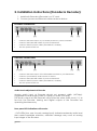
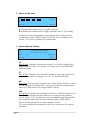
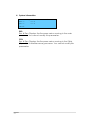
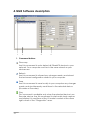
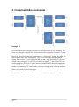
USER MANUAL
EtherMPX v3
Website: http://www.sigmacom.gr
Contact: [email protected]
Support: [email protected]
DOCUMENT REVIEWS
Date
01/03/2014
2
Version
1.0
Notes
Initial release
Dear customer,
After introducing our DDS-30 FM Exciter in 2010, the first in the world capable to
accept Digital MPX (MPX over AES), it was time to solve another problem: there was
no Digital MPX STL in the market! Also, the existing Analog MPX STLs could not meet
our high standards in order to exploit the full capabilities of DDS-30.
That’s why we decided to design a Digital MPX STL, which could transport Digital MPX,
beside the classic analog MPX, analog L/R, and digital L/R (over AES) modes. Since
we are big fans of the “everything IP” concept, we couldn’t select something else
than IP transmission!
In your hands, you have the EtherMPX IP STL, which is the result of our research and
development. Since version 3, an LCD user interface and SFN over IP capabilities
added, so you don’t need GPS receivers any more!
Always with 24bit professional high-end audio performance and minimal latency, we
could compare the performance of EtherMPX to a cable! Even if EtherMPX is
designed to be a perfect match with our DDS-30 FM Exciter, you can use it to deliver
analog MPX to any other exciter, and you will notice immediately the difference
compared to any analog FM STL.
So, enjoy using your EtherMPX and thank you for selecting us for your business!
Sigmacom Broadcast
March 2014
3
Contents
4
Page
1. Hardware description
a. The front panel
b. The rear panel (Encoder)
c. The rear panel (Decoder)
5
5
5
6
2. Installation instructions
a. Encoder connections
b. Decoder connections
c. Audio level adjustments
d. Rear panel LED indicators
e. Front panel LED indicators
f. Default settings
g. Network considerations
7
7
7
7
7
8
8
8
3. LCD menus
a. Navigate the menus
b. Modify parameters
c. The operational mode menu
d. The audio level menu
e. The network settings menu
f. The system information menu
9
9
9
9
10
10
11
4. NMS Description
a. Command buttons
b. Devices list
c. Device properties
d. Silence Detector configuration
e. Diagnostics
12
12
13
13
14
15
5. Implementation examples
a. Multicast with VLANs
b. Unicast
16
16
17
6. Technical specifications
18
1. Hardware description
The front panel (Encoder / Decoder):
1
1.
2.
3.
4.
2
3
4
LCD Display
Navigation buttons
Monitor output
Status LEDs
The rear panel (Encoder):
1 2
3
4
5
6
7
8
1. Unbalanced MPX input (BNC female)
2. Excessive input level alarm LEDs (L/R)
3. Right channel balanced input (XLR3 female)
4. Left channel / MPX balanced input (XLR3 female)
5. AES/EBU balanced input (XLR3 female)
6. 10/100 Ethernet port (RJ45 female)
7. RS232 port (DB9 female)
8. 10MHz/1PPS input (BNC female – SFN option)
9. On/Off power switch
10. 100-240VAC power input connector (IEC)
5
9
10
The rear panel (Decoder):
1 2
3
4
5
6
7
8
1. Unbalanced MPX output (BNC female)
2. Unbalanced AUX MPX input (BNC female)
3. Right channel balanced output (XLR3 male)
4. Left channel / MPX balanced output (XLR3 male)
5. AES/EBU balanced output (XLR3 male)
6. 10/100 Ethernet port (RJ45 female)
7. RS232 port (BD9 female)
8. 10MHz/1PPS output (BNC female – SFN option)
9. On/Off power switch
10. 100-240 VAC power input connector (IEC)
6
9
10
2. Installation instructions (Encoder & Decoder):
1. Install both Encoder & Decoder in a 19” rack.
2. Connect power and Ethernet cables as shown below:
Encoder connections
[1]
•
•
•
•
[2]
[4]
[3]
Connect the MPX output of your audio processor / stereo encoder
Connect the RJ45 LAN cable of your local network
Connect the IEC power cable (100-240VAC, 50-60Hz)
Turn the power switch on
Decoder connections
[1] [2]
•
•
•
•
•
[3]
[5]
[4]
Connect the MPX output of the EtherMPX Decoder to your FM Exciter
Connect your backup audio source to AUX IN
Connect the RJ45 LAN cable of your local network
Connect the IEC power cable (100-240VAC, 50-60Hz)
Turn the power switch on
Audio levels adjustment at Encoder
Analog audio input at Encoder should not exceed +6dBu (4.37Vpp).
Suggested nominal range is 0dBu (2.19Vpp) to +4dBu (3.47Vpp).
The audio outputs at the Decoder will provide the same audio level (1:1) as
fed into the Encoder. Analog and digital outputs of the Decoder are
operating simultaneously.
Rear panel LED indications at Encoder:
- OVFL LEDs (two, one for each analog input): Indicates extremely audio level
that needs immediate attention, otherwise damage may occur at analog
input stages of the Encoder.
7
Front panel LED indications (Encoder & Decoder):
- PWR LED: Indicates that power is turned on
- LINK LED: Indicates that an Ethernet connection is present.
- ACT LED: Indicates that audio transmission is active.
Note: When Encoder is configured in “Unicast” mode and powered on,
it searches for the Decoder (ACT LED is blinking every second). When a
connection is established, ACT LED at Encoder & Decoder stay always
on. If connection is lost, Encoder will cease transmission after 10 minutes
and will start the search sequence each 17 seconds.
Default settings:
- Encoder default IP: 192.168.1.90 / 24
- Decoder default IP: 192.168.1.91 / 24
- Factory setup: Analog MPX, Unicast
Network considerations:
If you have multiple EtherMPX devices in the same network (like 1 Encoder
and 2 or more Decoders), you MUST change the IP addresses of the devices
accordingly to avoid IP conflicts (two devices with the same IP in the same
network).
If you have multiple networks or other traffic reaching the EtherMPX Encoder
or Decoder, you MUST filter it. A recommended practice is to make network
segmentation by using VLANs.
It is strongly recommended to use transparent bridge Ethernet links with
sufficient bandwidth and low jitter in order for the EtherMPX system to operate
normally. The latency, delay variance and fragmentation caused by routing,
is forbidden for real-time traffic such as EtherMPX produces.
The required bandwidth for L/R mode is roughly 2.5Mbit/s, and for MPX mode
is around 4.8Mbit/s.
The audio buffer size at the decoder side depends on the network jitter you
have in your transmission network. Select an appropriate buffer size to
compensate the instability of your transmission network, otherwise you will
experience audible audio artifacts (“clicks” and “pops”) due to packet loss or
drops.
Always consider that an increased buffer size results into additional latency to
the audio delivered.
8
3. LCD menus:
From the LCD menus the user can view or modify some basic
parameters (described below). To control all system parameters, you
have to use the EtherMPX NMS (Network Management System)
software.
To navigate through the menus:
You can use the “UP” and “DOWN” buttons in the front panel, to
navigate through the User Interface menus displayed in the LCD.
To modify a parameter:
Press once the “OK” button and a blinking cursor should appear
in the screen. Use the “UP” and “DOWN” arrow buttons to move
the cursor over the parameter you want to modify. When you set
the cursor over the desired parameter, click once again the
“OK” button. Now you can use the “UP” and “DOWN” buttons to
modify the parameter.
When done, click “OK” button again. A confirmation menu appears
“SAVE? Y/N” where you can select “Y” if you want to apply and save
the new settings, or “N” to discard any changes you made.
If you don’t push any button within 30 seconds, the system discards any
changes and returns to the main menu.
1. Menu: Operational mode
Format :
Source :
IP Mode:
MPX
Analog
Unicast
More>
Format:
Enc & Dec: Select the audio format you need to transport
through EtherMPX. You can select between “MPX” or “L/R”.
Source:
Enc only: Select the source port of the Encoder. You can select
between “Analog” or “Digital” (AES/EBU) input.
IP Mode:
Enc only: Select the transmission mode. If you want to feed only
one EtherMPX Decoder in your network, select “Unicast”. If you
need to feed more than one EtherMPX Decoders simultaneously,
select “Multicast” (Destination IP: 239.255.255.239).
9
2. Menu: Audio level
Input
A
B <Back
dBFS
-10.3
More>
A: Displays the audio level of L/MPX channel
B: Displays the audio level of Right channel (only in L/R mode)
Audio levels are displayed as a bar graph (VU meter) and as
numerical value in dBFS. Please note that this is a display only
menu. You cannot modify any parameter.
3. Menu: Network settings
SIGMACOM ENCODER
ID :
192.168.001.090
IP :
SFN:Off
Att: 0.0
More>
<Back
ID:
Enc & Dec: Displays the device name. You cannot modify this
parameter from the LCD menu, you have to use the EtherMPX
NMS software.
IP:
Enc & Dec: Displays the device IP address. You can modify this
parameter within the range of 1.0.0.1 to 254.255.255.254.
Att:
Dec only: Displays the analog output attenuation setting. A value
of 0dB means no attenuation. You can modify this parameter in
steps of 0.5dB within the range 0.0dB to Mute.
SFN:
Enc & Dec: Displays the operational status of the SFN option. The
“Off” status means that the device is running on the internal
clock. When “On” the device is synchronized to the Best Master
clock elected from the network (please refer to IEEE1588v2
protocol specifications for more details on this).
You can modify this parameter only if you have the SFN option
installed.
10
4. System information
DSP =
CPU =
<Back
Sigmacom EtherMPX v3
v3.4
v3.4
DSP:
Enc & Dec: Displays the firmware version running in the main
processor. You cannot modify this parameter.
CPU:
Enc & Dec: Displays the firmware version running in the O&M
(Operation & Maintenance) processor. You cannot modify this
parameter.
11
4. NMS Software description
1
2
3
4
1. Command buttons
Discovery
Use this command to auto detect all EtherMPX devices in your
network. Your computer must be in the same subnet as your
devices are.
Refresh
Use this command to discard any changes made, and reload
the last saved configuration stored in your computer.
Save
Use this command to save locally in your computer any changes
made, and simultaneously send them to the selected device
(Encoder or Decoder).
Play
This command is available only when the selected device is an
Encoder device. Use this command to start audio level capture
and display it in real time at the VU meter located at the down
right corner of the “Diagnostics” area.
12
Stop
This command is available only when the VU meter is running.
Use it to stop audio level capture from Encoder.
2. Devices list
In this are you will be displayed all devices discovered in your
network when you used the “Discovery” command button.
icon: Indicates an Encoder device
icon: Indicates a Decoder device
Next to the icon, the device name and MAC address is displayed.
3. Device properties
When you click on a device in the “Devices list” area, its properties
and parameters are displayed here.
•
•
•
•
•
•
•
•
•
•
•
13
System type: ENCODER or DECODER (non modifiable)
DSP version: The firmware version running in the main processor
of the selected device (non modifiable)
MAC address: The MAC address of the network interface of the
selected device (non modifiable)
Serial number: The production serial number of the selected
device (non modifiable)
System name: View or modify the human friendly name of the
selected device. Highly recommended if you have more than
one Encoder or more than one Decoder in your network. This
helps you to identify the proper device to manage.
System IP: View or modify the IP address of the selected device.
Gateway IP: View or modify the network gateway IP address of
the selected device.
Network mask: View or modify the network mask of the selected
device.
VLAN: Reserved for future releases. User cannot modify this.
SFN option: Only available when SFN option is installed in the
selected device.
Audio routing: This is a Decoder only functionality. View or modify
the audio route of the selected Decoder. Use the drop down
menu to select between the available options:
o Force external: Take the audio from AUX IN and pass it to
the MPX OUT
o Force internal: Take the audio from Ethernet and pass it to
the MPX OUT
o Auto detect: Enables the Silence Detector (see below).
•
•
•
•
•
•
•
•
Audio type: View or modify the audio format of the selected
device. Use the drop down menu to select between “MPX” or
“L/R”.
Audio source: This is an Encoder only functionality. View or
modify the input source of the Encoder. Use the drop down
menu to select between “Analog” or “Digital” (AES/EBU) inputs.
TX type: This is an Encoder only functionality. View or modify the
audio over IP transmission mode at the Encoder. Use the drop
down menu to select between “Unicast” (one Encoder to one
Decoder) or “Multicast” (one Encoder to many Decoders). When
in “Multicast” packets sent from Encoder, will have destination IP
as 239.255.255.239.
Remote IP: This is an Encoder only functionality and it is enabled
only when “Unicast” is also selected. View or modify the IP
address of the Decoder you will be sending audio to.
Bounded to: Reserved for future releases, has no effect.
Buffer size: This is a Decoder only functionality. View or modify the
audio buffer size of the selected Decoder. Please refer to
“Network considerations” section above.
Threshold: This is a Decoder only functionality and it is enabled
only when “Auto detect” audio routing is selected. This is a
parameter of the integrated Silence Detector in the Decoder,
and defines the audio level threshold to start a countdown timer
before it bridges the AUX IN to the MPX OUT connector
(assuming that the audio over IP is lost).
Timeout: This is a Decoder only functionality and it is enabled only
when “Auto detect” audio routing is selected. This is a parameter
of the integrated Silence Detector in the Decoder, and defines
the initial value of the countdown timer.
Silence Detector example: Threshold = -18dBu, Timeout = 20 sec.
If the audio level coming from the EtherMPX encoder is below
-18dBu for 20 consecutive seconds, the Silence Detector will assume
that the audio over IP is lost, and will bridge the AUX IN to the MPX
OUT connector.
When the audio level is restored above -18dBu for 5 consecutive
seconds, the Silence Detector assumes that the audio over IP is OK
and disconnects the AUX IN from the MPX OUT connector.
If your program has long periods of silence or long pauses between
songs and talent, it is recommended to set the audio routing of the
Decoder to “Force internal”.
Note: The 5 seconds restoration timer is factory fixed and cannot be
modified by the user.
14
4. Diagnostics
When you have selected a device in the “Devices list” area, you
can use the following tools:
•
•
15
Ping response: Click with your mouse the rectangular shape,
to perform an ICMP ping towards to the IP address of the
selected device. The ping is originating from your computer IP
address, so it must be in the same subnet as the device is.
If there is a ping response, the shape turns in green color and
the response time is displayed.
If there is no response within a second, the shape turns into
red color and perform consecutive retries to ping every 3
seconds. To stop retrying, just click with your mouse in the
rectangular shape.
Audio level: This is an Encoder only functionality. This is a real
time VU meter, which displays the audio level of the selected
Encoder. To start monitoring the audio level, select the
Encoder device you want, and click the “Play” button on the
top strip. To stop the audio monitoring, just click the “Stop”
button next, or select some other device from the “Devices
list”. Keep in mind that audio monitoring causes a reverse
direction IP traffic of about 100-200kbit/s.
5. Implementation examples
Example 1:
Two different radio programs must be transported to two different TX
sites over single IP radio links. We need both programs at each TX site.
Because two Encoders are operating in “Multicast” mode (in order to
feed more than one Decoders), they must be logically separated
inside the network. For this purpose, we are using separate VLANs for
each radio program (VLAN 10 for radio program 1, and VLAN 20 for
radio program 2). Even if there are two separated network segments,
you should define unique IP addresses to each device. Note that the
ports connected to IP radio links, must be configured as trunk ports to
allow all VLANs to pass through.
To achieve this, you need Ethernet switches that support VLANs.
16
Example 2:
Two different radio programs must be transported to two different TX
sites over single IP radio links. We need only one program at each TX
site.
Because two Encoders are operating in “Unicast” mode (each one is
paired to only one Decoder), they can co-exist in the same network
without the need of VLANs. Of course each device must also have a
unique IP address.
To achieve this, you can use ordinary plain Ethernet switches.
17
6. Technical specifications
GENERAL
DECODER
Model name
EtherMPX v3
Output name
Port A
Dimensions
19” 1U chassis
Output type
Digital electrical interface
Power supply
230VAC 50Hz, 12W
Connector
XLR-3 male
Operating temp
-20 to +60 Celsius
Impedance
110 Ohm balanced, transformer isolated
Transport protocol
Proprietary UDP Unicast or Multicast
Format
AES3
IETF RFC2474 compliant
Maximum data rate
12.288 Mbit/s
Audio sample rate
48kHz for L/R output, 192kHz for D-MPX
Audio sample resolution
24 bit
Output name
Port B
Output type
Analog electrical interface - 2 outputs
Connector
2 x XLR-3 male (balanced R, L/MPX)
1 x BNC (female unbalanced MPX only)
QoS management
Audio compression
None (Linear PCM)
Audio resolution
8 – 24bit for Digital L/R & MPX input
24bit for Digital L/R & MPX output
24bit for Analog L/R & MPX output
Audio sample rate
8 – 192kHz input for Digital L/R input
174-192kHz input for Digital MPX input
48kHz internal for Analog L/R input
192kHz internal for Analog MPX input
L/R mode: 5mS (up to 40mS on busy net)
MPX mode: 2,5mS (up to 20mS on busy)
Impedance
1 kOhm
Audio latency
DAC resolution
24 bit
DAC sample rate
48kHz for L/R output, 192kHz for A-MPX
Network usage
L/R mode: 2,37 Mbit/s typ
MPX mode: 4,74 Mbit/s typ
Audio monitor
Stereo ¼” Female jack in front panel
DAC THD+N
-108dB (0.0004%) at 48kHz L/R out
-96dB (0.0015%) at 192kHz A-MPX out
DAC SNR
129dB at 48 or 192kHz
DAC Dynamic range
129 dB (A weighted) at 48 or 192kHz
ENCODER
Input name
Port A
Channel separation
124 dB at 48kHz L/R output
Infinite at 192kHz A-MPX output
Input type
Digital electrical interface
Reference output
3.47Vpp (+4dBu) for 0 dBFS
Connector
XLR-3 female
Out BW @ 48kHz SR
-0.1dB @ 21.8 kHz
Impedance
110 Ohm balanced - transformer isolated
Out BW @ 192kHz SR
-0.1dB @ 87.2 kHz
Supported formats
AES3, IEC60958, S/PDIF
Maximum data rate
12.288 Mbit/s
Audio sample rate
32 - 192 kHz (174-192kHz for D-MPX)
SFN Operation
Ouputs
1x10MHz, 1x1PPS
Connector
BNC Female
Impedance
50 Ohms
Audio sample
resolution
24 bit
Input name
Port B
Delay compensation
Auto up to 20mS (basic version)
Input type
Analog electrical interface - 2 inputs
Synchronization
PTP (IEEE-1588), <5nS accuracy
Connector
2 x XLR-3 female (balanced R, L/MPX)
1 x BNC female (unbalanced MPX only)
Impedance
1 kOhm
ADC resolution
24 bit
ADC sample rate
48kHz for L/R input, 192kHz for A-MPX
ADC THD+N
-106dB (0.0005%)
ADC Dynamic range
121 dB (no weighting)
Channel separation
135 dB
Reference input
3.47Vpp (+4dBu) for 0 dBFS
Input BW @ 48kHz
SR
-0.1dB @ 20 kHz
Input BW @ 192kHz
SR
-0.1dB @ 80 kHz
NOTE: Technical specifications are subject to change without notice. Please contact
us if you have questions, or to get latest information and updates.
Sigmacom Broadcast support:
[email protected] - or call +302312209905.
18