1
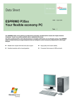
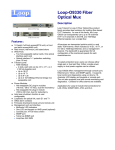
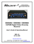
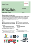
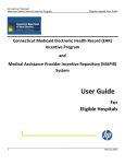
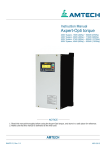
OTX627 COFDM Digital Video Transmitter User's Guide & Operating Manual REV. A – 14 Jan 2009 http://www.avalonrf.com/ Avalon RF, Inc. • 344 Coogan Way • El Cajon, CA 92020 Phone: (619) 401-1969 • Fax: (619) 401-1971 • Email: [email protected] AVALON RF, INC. OTX627 Series User’s Guide & Operating Manual Page ii AVALON RF, INC. OTX627 Series User’s Guide & Operating Manual 1. 2. 3. Page iii Table of Contents General ................................................................................................1 Figure A – OTX Series Controls and Connectors.................................3 Video ...................................................................................................4 Audio ...................................................................................................4 Meta Data ............................................................................................4 Talk Back Audio Channel (Optional) ....................................................4 Two Way Digital Data Link (DDL) (Optional) ........................................4 RF Outputs ..........................................................................................4 Specifications & Interfaces...................................................................5 RF Specifications..........................................................................5 Video Specifications .....................................................................5 Audio Specifications .....................................................................5 Meta Data (Telemetry/User Data) (Option) ...................................6 Control Interface ...........................................................................6 Power ...........................................................................................6 Connector/ Interface .....................................................................6 Physical ........................................................................................6 User Interface ......................................................................................7 Setup ...................................................................................................7 Electrical Interface ...............................................................................7 Table 2 – Current Consumption ...........................................................8 Interconnecting ..................................................................................10 Figure C – Power...............................................................................10 Figure D – Video................................................................................10 Figure E – Audio ................................................................................11 Figure F – Data/Programming Input...................................................11 Mounting............................................................................................12 Mechanical Data ................................................................................12 Figure G – OTX Series Mechanical Outline .......................................13 Environmental Conditions ..................................................................14 Operating the transmitter. ..................................................................15 Operater Controls & Indicators...........................................................15 General Guidelines ............................................................................17 Table 4 – Minimum Safe Distance .....................................................18 Warranty ............................................................................................19 AVALON RF, INC. OTX627 Series User’s Guide & Operating Manual 1. Page 1 General The OTX series rugged transmitters are intended for use in military, homeland security, mobile security, broadcast and motion picture production. The OTX Series is a digital video transmitter using COFDM for robust wireless video. The unit has 16 channels within a frequency range of 2.4GHz-2.483GHz and an optional extended range of 2.05GHz2.5GHz (for defense or licensed users only). The transmitter carries video, stereo audio & data over the wireless link. The data channel can be used for telemetry in UAV applications. Some models have dual video inputs that can be used conveniently with standard & night vision cameras. This is particularly useful for robotic & UAV applications. All transmitters offer the following features: • • • • A single broadcast quality video channel. Stereo audio. Meta-data @ 38.4kbps 4 power levels Optional features (each ordered individually). • Two-way UHF Wireless Data Link (WDL) to a ODX series receiver. • Talk back audio channel. AVALON RF, INC. OTX627 Series User’s Guide & Operating Manual Page 2 1 1 5 3 2 3 4 5 2 Top View Main Antenna 4 Bottom View Power/Video Input – see Figure C Data Input – see Figures F Video Input – see Figure D Audio Input – see Figure E Figure A – OTX Series Controls and Connectors AVALON RF, INC. OTX627 Series User’s Guide & Operating Manual 6 7 8 9 10 Side Views Power Switch Power LED Indicator Status Indicator RF Power Switch Channel Select Switch 10 9 7 8 6 Figure A – OTX Series Controls and Connectors (contd) Page 3 AVALON RF, INC. OTX627 Series User’s Guide & Operating Manual 1.1 Page 4 Video. Depending on the model, the unit features either 1 or 2 video inputs. The video inputs are standard 75 ohm impedance and accept composite video with negative sync tips. In case of dual video inputs, the switchover between Video A & Video B can be made via a serial mode command. 1.2 Audio. The audio interface is stereo. Both left & right channels are balanced line level inputs. The input impedance is high – 100K. 1.3 Meta Data. The transmitter also carries digital meta data with the video. The standard baud rate is 38.4K with a 8N1 format. 1.4 Talk Back Audio Channel (optional). The talk back audio channel allows the transmit side (e.g camera operator on the transmit side) to receive instructions from the operator at the receiver’s side. It drives an earpiece or the output can be used with a PA system. 1.4 Two Way Wireless Digital Link (WDL) (optional). The WDL serves as a Pan-Tilt-Zoom (PTZ) / general-purpose twoway RS422/RS485 digital link. 1.5 RF Outputs. The transmitters have two RF outputs (Only 1 for a standard unit, without WDL or Talk Back Audio Option). A female SMA connector for the main transmitter and a BNC for the WDL. Both outputs feed antennas, either directly or through a cable. AVALON RF, INC. OTX627 Series User’s Guide & Operating Manual 2. Page 5 Specifications & Interfaces RF Specifications RF Output: RF Impedance: Frequency Range: +27 dBm max. (3 selectable power levels) 50 ohms ISM bands - 900 MHz (902-928 MHz) 2.4 GHz (2.40 – 2.483 GHz) Other frequency bands available in UHF, L band & S band (for military, government or if user has licensed frequencies) over the frequency range of 250 MHz – 2.7 GHz Modulation: Channel BW: No of Channels: Modulation: FEC: Guard interval: COFDM 6,7 or 8 MHz 16 channel capability QPSK 1/2, 2/3 1/32, 1/16 Video Specifications Video Standard: Video Input: Video Compression: Video Resolutions: Bit Rate: NTSC or PAL Composite or Y/C MPEG-2 Main profile @ Main Level I, P and B frames supported Full D1 (720 x 486 NTSC, 720 x 576 PAL) @ 30 fps; CIF or DVD 4 – 8 Mb/s depending on modulation parameters Audio Specifications Audio Input: Impedance: Audio Compression: Bit Rate: Sampling Rate: Stereo inputs- Left & Right Balanced High Impedance 100K MPEG2 Audio 128Kb/s/ch 48KHz AVALON RF, INC. OTX627 Series User’s Guide & Operating Manual Page 6 Meta Data (Telemetry/User Data) (Option) Data Interface: Baud Rate: RS232C, 8N1 setting 38.4K Control Interface Interface: Baud Rate: Usage: RS232C, 8N1 upto 38.4K User loadable Frequency list of Channels through GUI; SID (system ID settable for each channel) Power Input: Consumption: 12V nominal; 9- 20V DC Unregulated 6W typical @ max. Output power of +27 dBm Connector/ Interface RF Output: SMA(f) 50 ohm I/O Connectors Power: 4 pin Lemo Video: BNC (f) for single video unit; 2 x Mini-BNC(f) for 2 video input unit Audio: 5 pin Lemo Data/ Control: 7 pin Lemo Physical Dimensions: Weight: Approx. 3.5” x 4.5” x 1” Approx. 6.5 oz (180 gms) AVALON RF, INC. OTX627 Series User’s Guide & Operating Manual 2.1 Page 7 User Interface. a) On/Off Switch. The OTX series transmitters have a electronic on/off switch. The switch must be held pressed for at least 3 sec to turn the unit on or off. This shuts off power to the entire transmitter. b) Power on LED. This is a red led to indicate the unit is turned on. c) Status LED The status led is bi-color and indicates normal operation or programming mode. d) Hands Free Back Channel (optional). This option allows the receiver operator to communicate with the transmitter operator via a headset that includes an earpiece and a microphone, when the transmitter is on air. 2.2 Setup. The OTX series transmitters have the following setups: a) RF Channel. b) Output Power Level. 2.3 Electrical Interface. The transmitter has the following interfaces: 2.3.1 Power Input a) The transmitter requires 9-20V dc. The power source can be unregulated (like a battery) or a dc adaptor as long as the ripple does not exceed 1Vp-p. When using a dc adaptor or powering the unit from a vehicle battery, an external filter may be necessary (depending on the situation) to provide reasonably clean power to the transmitter. AVALON RF, INC. OTX627 Series User’s Guide & Operating Manual Page 8 b) The input is electronically switched and protected against reverse polarity. There is also a ‘under-voltage lockout’ mechanism which ensures that there is at least the minimum operating voltage present to turn on the transmitter. In case the input voltage is lower than the minimum, the transmitter will not turn on. The user will see only a brief flash of the red led. c) Typical input current consumption for the basic configuration is (with video present): Model OTX627 OTX627 OTX627 Output Power Input Current +27 dBm (0.5W) Approx 600mA +23.5 dBm (200 mW) Approx 450mA +20 dBm (100 mW) Approx 350mA Table 2 – Current Consumption Addition of option 11 (WDL) will increase the current draw by a maximum of 170mA. 2.3.2 Video Input. a) The video input accepts RS170, CCIR, NTSC or PAL signals. The type of video input is set through the GUI provided. b) Input signal is composite video 1Vp.p with a negative sync tip of 0.3V. c) The input impedance is 75 Ω (ohm). 2.3.3 Audio 1 and Audio 2 Inputs. The audio inputs accept balanced line level signals of 1Vp.p. and have an input impedance of 100K Ω (ohm). 2.3.4 "Talk back" audio channel to the transmitter operator (optional). The “talk back” output drives an electromagnetic earpiece (headset speaker). AVALON RF, INC. OTX627 Series User’s Guide & Operating Manual Page 9 2.3.5 Two Way Wireless Digital Link (WDL) (Option 11) The WDL is a 9.6KBaud (standard, other Baud rates are supported) Half-Duplex RS485 compatible serial interface. 2.3.6 Main RF output to antenna. The main RF output connector is a 50 Ω (ohm) female SMA receptacle. 2.3.7 Wireless Digital Link (WDL) RF output. The WDL RF output is via a 50 Ω (ohm) BNC connector. Maximum output power is +24 dBm (0.25W). The main RF and the WDL RF outputs are identical on all the transmitter versions. AVALON RF, INC. OTX627 Series User’s Guide & Operating Manual 2.4 Page 10 Interconnecting. All interfaces to/from the transmitter are available through the following connectors: 2.4.1 a) Power Input. Pin Function Number 1 Power Return (-) 2 3 4 Power Input (+) Figure C – Power b) Video Input. Depending on the model, there is provision for 1 or 2 video input signals. In case of the single video input, the connector is a 75 Ω (ohm) BNC while the 2 video inputs style has a 75 Ω (ohm) MiniBNC connector. Figure D – Video AVALON RF, INC. OTX627 Series User’s Guide & Operating Manual Page 11 c) Audio Input. Pin Number 1 2 3 4 5 Function Audio Return Audio L + Input Audio R + Input Audio R - Input Audio L - Input Figure E – Audio d) Data/Programming Input. Pin Function Number 1 Data GND/ Return 2 Program Signal 1(DO NOT CONNECT/ USE) 3 Program Signal 2 (DO NOT CONNECT/ USE) 4 5 RS232 In 6 RS232 Out 7 Data GND/Return Figure F – Data/Programming Input AVALON RF, INC. OTX627 Series User’s Guide & Operating Manual 2.5 Page 12 Mechanical 2.5.1 Mounting. Clamping (or hard mounting) is the only method of mounting advised for all fixed installations. Avalon RF has a special mounting plate available. Please ask for details. For mobile camera usage, Anton Bauer mounting is also available at extra cost. Please contact us for details. The transmitter is designed for convection (free air flow) cooling and no forced air-cooling (such as a fan) is necessary. The user should simply take care to provide room for proper airflow. The unit can be mounted on any side but it should not be sandwiched between other equipment. Another precaution to take when installing is to make sure there is no source of strong electro-magnetic fields nearby. 2.5.2 Mechanical Data. a) Size 3.07” x 1.73” x 1.0 (see Figure G) 78mm x 44mm x 25.4mm b) Weight <5.6 oz. <158 gram c) Shipping weight <32 oz. <900 gram AVALON RF, INC. OTX627 Series User’s Guide & Operating Manual Figure G – OTX Series Mechanical Outline Page 13 AVALON RF, INC. OTX627 Series User’s Guide & Operating Manual 2.6 Environmental Conditions. Page 14 The OTX Series is designed to meet the following environmental conditions: 2.6.1 Operating temperature -4° to 122° F -20° to 50° C 2.6.2 Storage temperature -13° to 150° F -25° to 65° C 2.6.3 Vibration 1.5G, from 10Hz to 2KHz, sine wave, 3 axis 2.6.4 Shock 15G, 25msec, half sine wave, three axis 2.6.5 Humidity 5 to 95%, non-condensing 2.6.6 Inclination Any 2.6.7 Altitude -1500 feet to 15,000 feet -450 meter to 4,500 meters AVALON RF, INC. OTX627 Series User’s Guide & Operating Manual 3. Page 15 Operating the transmitter. Before applying power, make sure all connectors and all antennas are hooked up. NOTE The transmitter will not transmit unless it has an antenna. 3.1 The transmitter has three operator controls and two indicators: a) On/Off switch. The On/Off control is an electronic circuit & the switch must be kept pressed for 3 seconds to turn the unit on or off. The electronic switch also has ‘under voltage lockout’ that prevents the unit from turning on or turns it off, if the input voltage is less than the minimum voltage for reliable operation. b) Channel select. The unit has a 16-channel capability. The channels are preconfigured in the ISM band (except for defense or export units) with the most optimum settings but can be changed by the user (authorized user’s only). The channel selection is through a 16 position rotary switch & numbered in hexadecimal format – 0 through F. In hexadecimal notation, A stands for 10, B for 11 and so on. c) RF Power Selection The RF power switch is a 10 position switch with currently 3 power levels available. The top 3 settings 7,8 and 9 have the maximum power output for the model. Each lower setting is 3 dB (1/2) less rf power. As an example, for the OTX627, settings 7,8 & 9 will have the full +27 dBm (0.5W), setting 6 will be +24 dBm (0.25W) & so on. The user is advised to use the lowest power setting & increase power only if the reception is poor. AVALON RF, INC. OTX627 Series User’s Guide & Operating Manual Page 16 d) Power LED The power led is red & when lit, indicates the transmitter is on. e) Status LED This led is green during normal operation & yellow during programming/ set-up. 3.2 The wireless data link is a secondary/utility link that is used to transfer data/voice in the reverse direction. It is a narrow band UHF link operating in the low UHF license-free band. Following are the characteristics: a) VOICE: Voice is transmitted from the receiver (ODX side) to the Transmitter side (OTX side). It is implemented as a digital wireless microphone and only the headset microphone is used on the ODX side & only the earpiece is used on the OTX side. The microphone is an electret mic. b) DATA: The data rate is 9.6KBaud fixed (other data rates supported) on a RS485 interface. AVALON RF, INC. OTX627 Series User’s Guide & Operating Manual 3.3 Page 17 General Guidelines The choice of a Transmitter and the Antenna to be used is dictated by power consumption, required distance of operation of the link, if it is a fixed or a mobile environment, the space constraints, the location itself (indoors or outdoors, presence of nearby objects like trees, bridges, etc.) and etc. Avalon RF will work with the user to determine the right combination. Placement/positioning of the transmitter antenna is important for proper operation of the wireless video link. The antenna shipped with the unit is omni-directional, which means it will radiate in all directions and when upright (vertical) will be vertically polarized. The receiver side antenna’s then must also be mounted vertically. While the above method would be the usual / most common way, certain applications need a different placement. As an example, to transmit between floors in a high-rise building, the transmit & receive antennas can be small, directional, high gain panel antennas, mounted horizontally, directly ‘looking’ at each other. Circular polarized antennas are more expensive, but give a far better performance, especially in mobile applications. For proper operation of the wireless link, the transmitter antenna should be kept clear of metal objects, trees, buildings, etc. If the transmitter is mobile such as on a video camera, ensure the antenna is sufficiently clear of the operator’s body, especially the head. A 2.4 GHz link is a line-of-sight communications, which means the receive antennas should ‘see’ the transmit antenna. Another very important aspect relates to health hazards from RF energy absorption in the body. To minimize the risk, we ask that the user ENSURE the minimum distance of the transmitting antenna from the human body per Table 4. These values have been calculated per FCC Bulletin OET65, Supplement C & related documents. AVALON RF, INC. OTX627 Series User’s Guide & Operating Manual Minimum Distance from Body (in Inches) Power @ 2.4 Antenna 0 dBi 3 dBi 10 dBi 16 dBi GHz Gain +20 dBm 2” 3” 4” 8” (100mW) +24 dBm 3” 4” 8” 16” Distance (250mW) +27 dBm 6” 9” 16” 32” (500mW) Table 4 – Minimum Safe Distance Page 18 27 dBi 48” 84” WARNING: An Antenna extender cable shipped with the OTXXX is meant to hold the antenna at the minimum safe distance from the human body. This extender cable MUST be used whenever the Transmitter is operated in a mobile environment (such as on a camera) and the user should mount the transmitter in a way that does not defeat the purpose of this cable. If the transmitter is mounted in a manner other than intended with the extender cable, it SHALL be the user’s responsibility to ensure the above minimum distance from ‘any’ human being. Avalon RF will help/advise you if necessary. If the antenna you received is not one of the above, use the next higher distance or call/e-mail Avalon RF. Operating range will depend on the transmit and receive antennas used - a wide choice of antennas is available from Avalon RF. Please visit the website (www.avalonrf.com) for more details. AVALON RF, INC. OTX627 Series User’s Guide & Operating Manual Page 19 Warranty The Avalon RF Warranty covers Mechanical and Electrical defects for each of the components in your Avalon RF equipment. We will repair or replace the defective part at our cost during the warranty period. Cost is defined as the cost of the component(s) plus our time to install and test the replacement part. Warranty covers parts and labor. The warranty period is assumed to be 1 Calendar year unless otherwise specified on invoice. The warranty does not cover failure due to acts of God, failure caused by power outages by the power company, or failure caused by third party components. This includes, but not limited to, earthquakes, flood, electrical storms, power or transformer failure and other acts which are unforeseeable, any component supplied to Avalon RF by the customer or damaged caused to Avalon RF components by customer supplied components.