1
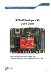
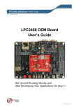
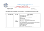
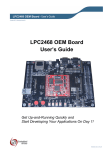
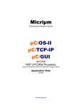
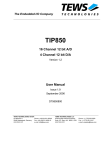
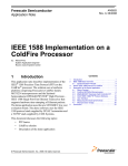
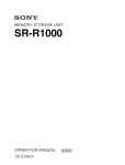
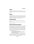
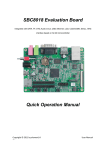
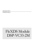
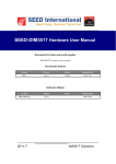
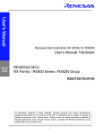
SEED-DEC138 Hardware User Manual 2010-07 DSP Development Systems Current version SEED-DEC138 Hardware User Manual Document History Rev. No History Date Board History Rev. No History Date SEED-DEC138 Hardware User Manual SEED-DEC138 Preliminary Hardware User Manual SEED-DEC138 Preliminary Hardware User Manual Version:A 2010.11 http://www.seeddsp.com I IMPORTANT NOTICE SEED International reserves the right to make changes to its products or to discontinue any product or service without notice. Customers are advised to obtain the latest version of relevant information to verify that the data being relied on is current before placing orders. II Preface Read This Frist About This Manual This document describes the board level operations of the OMAP-L138. The SEED-DEC138 is based on the Texas Instruments OMAP processor. The SEEDDEC138 allows engineers and software developers to evaluate certain characteristics of the OMAP processor to determine if the processor meets the designers application requirements. Evaluators can create software to execute on board or expand the system in a variety of ways. Warranty The warranty period for all hardware and software products manufactured by SEED Electronic Technology Ltd is one year after shipment. SEED Electronic Technology Ltd guarantees free of charge repair or replacement for the manufacturer caused damaged products during warranty period. Software updates will be sent free of charge to the customer during warranty period. Information about Cautions The Boards contains Electro-static Discharge (ESD) sensitive devices. Take proper precautions to ground yourself before handling the board. This Document may contain cautions. A caution statement describes a situation that could potentially damage your software, or hardware, or other equipment. The information in a caution is provided for your protection. Please read each caution carefully. Trademarks SEED is trademark of SEED Electronic Technology Ltd. TI, XDS510, XDS560 are trademarks of Texas Instruments. Related Documents, Application Notes and User Guides Information regarding the OMAP-L138 Processor can be found at the following Texas Instruments website: http://www.ti.com Information about this production if you need assistance can be found at the following Seed International website: http://www.seeddap.com III Contents 1. 1.1 1.2 2. 2.1 2.2 2.3 3. 3.1 3.2 I Functional Overview ...........................................................................................1-1 Key Features ...............................................................................................1-1 Block Diagram: ............................................................................................1-3 Board Components ............................................................................................2-1 OMAP-L138 Processors Module ................................................................2-1 2.1.1 OMAP-L138 Processor .......................................................................2-1 2.1.2 DDR2 ...................................................................................................2-1 2.1.3 NAND FLASH ......................................................................................2-1 2.1.4 CPLD ...................................................................................................2-1 SEED-DEC138 Peripherals and Interfaces ................................................2-2 2.2.1 LCD .....................................................................................................2-2 2.2.2 AD Data Acquisition ............................................................................2-2 2.2.3 DA Converter Module ..........................................................................2-2 2.2.4 Ethernet Interface ................................................................................2-3 2.2.5 MMC/SD Media Card Interfaces .........................................................2-3 2.2.6 USB Interface ......................................................................................2-3 2.2.7 UART ...................................................................................................2-3 2.2.8 SATA ...................................................................................................2-3 2.2.9 JTAG Debugger Interface ...................................................................2-3 2.2.10 Expansion Bus ....................................................................................2-4 2.2.11 Clock and LED ....................................................................................2-4 Power Management Module .......................................................................2-5 2.3.1 Power Management Layout and Application ......................................2-5 2.3.2 Power Supply ......................................................................................2-5 Physical Description ...........................................................................................3-1 PCB Layout .................................................................................................3-1 Connector....................................................................................................3-2 3.2.1 J2 DA Output .......................................................................................3-4 3.2.2 J3 Electrical Motor Interface and AD Input Interface ..........................3-4 3.2.3 J4 Capture Interface ............................................................................3-4 3.2.4 Expansion Bus ....................................................................................3-5 3.2.5 J8 LCD Interface .................................................................................3-8 3.2.6 Power Cord..........................................................................................3-8 3.2.7 JTAG Pin Definition and DIP Switch ...................................................3-9 3.2.8 J25 SATA Interface .............................................................................3-9 Figure List Figure 1. SEED-DEC138 ...........................................................................................1-2 Figure 2: Block Diagram of the SEED-DEC138 ........................................................1-3 Figure 3: SEED-DEC138 Top Side ...........................................................................3-1 Figure 4: SEED-DEC138 Bottom Side ......................................................................3-2 II Table List Table 1: Connector ....................................................................................................3-3 Table 2: J2 Definition ................................................................................................3-4 Table 3: J3 Definition .................................................................................................3-4 Table 4: J4 Definition .................................................................................................3-5 Table 5: J6 Definition ................................................................................................3-6 Table 6: J23 Definition ..............................................................................................3-7 Table 7: J16 Definition ..............................................................................................3-7 Table 8: J24 Definition ..............................................................................................3-8 Table 9: LCD Definition ............................................................................................3-8 Table 10: J17 Definition ............................................................................................3-8 Table 11: J21 Definition .............................................................................................3-9 Table 12: DA Output Definition.................................................................................3-9 Table 13: J20 Definition ............................................................................................3-9 Table 14: J25 Definition ..........................................................................................3-10 III SEED-DEC138 Hardware User Manual Chapter 1 Functional Overview 1. Functional Overview Chapter 1 provides a description of the SEED-DEC138 along with the key features and a block diagram of the circuit board. 1.1 Key Features The SEED-DEC138 uses OMAP-L138 high performance processor from Texas Instruments. The OMAP-L138 is a dual-core device: a 300-MHz ARM926EJ-S MPU core and a 300-MHz C6748 VLIW DSP core. The SEED-DEC138 board provides rich peripheral interfaces. The SEED-DEC138 adopts the SEED standard DEC serial board structure that suit a wide variety of application environments. The SEED-DEC138 operates from +5V and +/-15V external power supply. The +5V input is converted into core voltage, +1.2V, +1.8V and +3.3V. The +3.3V supply is used for the DSP's I/O buffers and other chips on the board. The +1.2V is the DSP core voltage. The +1.8V voltage is used for the USB and DDR2. CPU power rails are sequenced on the module. 1-1 Chapter 1 Functional Overview Figure 1. SEED-DEC138 The SEED-DEC138 hardware key features include: OMAP-L138 from Texas Instruments: a 300-MHz ARM926EJ-S MPU and a 300-MHz C6748 VLIW DSP. 1-2 512Mb DDR2: K4T51163QG-HCF7 4Gb NAND FLASH: K9F4G08U0A-PCB0 2 UART: RS232 and RS485/RS232 (jumper selection) 2 USB port: OTG2.0 and HOST MMC/SD SATA 10/100 Mbps Port Ethernet Phy Motor port: 2 group eHRPWM AD: 6 channel 16 bit AD converter, input voltage range: -12V~ +12V DA: 4 channel 12 bit DA converter, output voltage range: -10V~ +10V or 0V~ +10V EXT_BUS: data bus, address bus, control signals, status signals, chip select signal, McBSP0,McBSP1 and etc. Interface voltage level +3.3V/ +5V LCD: TFT565 SEED-DEC138 Hardware User Manual 1.2 Block Diagram: The block diagram of the SEED-DEC138 is shown as below: ECAP0、1、2 HRPWM0、1 RS232 RS232 Transceivers RS232/485 RS232/485 Transceivers BUS Transceivers NAND CE3 FLASH CPLD CE2 CE4 DA CE4 AD CE4 E M I F A BUS Transceivers UART0 SN74LVTH16245A RJ45 EXT BUS CE5 UART2 ETH PHY DP83640/KSZ8001L RMII HARD DISK SATA O M A P L 1 3 8 DDR2/ MDDR MMC/SD0 DDR2 SPI1SPI0 VIDEO OUT SN74LVTH16245A LCD & TSC USB 2.0 OTG RTC USB 1.1 HOST BOOT MODE WATCH DOG +5V +3.3V +15V POWER1 +10V POWER4 +1.2V POWER2 -15V -10V POWER5 +1.8V POWER3 Figure 2: Block Diagram of the SEED-DEC138 1-3 SEED-DEC138 Hardware User Manual Chapter 2 Board Components 2. Board Components This chapter describes the operation of the major board components on the SEED-DEC138. It includes processors module, interfaces module and power management module. 2.1 OMAP-L138 Processors Module 2.1.1 OMAP-L138 Processor The SEED-DEC138 uses OMAP-L138 high performance processor from Texas Instruments. The OMAP-L138 is a dual-core device: a 300-MHz ARM926EJ-S MPU core and a 300-MHz C6748 VLIW DSP core. The OMAP-L138 sits at the U25 on the board. 2.1.2 DDR2 The SEED-DEC138 provides 512M DDR2 (K4T51163QG-HCF7). It is connected to the on-chip DDR2 space and sits at the U21 on the board. 2.1.3 NAND FLASH The SEED-DEC138 provides 512Mb x8 bit NAND FLASH (K9F4G08U0A-PCB0). It is connected to the on-chip EMIFA space and sits at the U22 on the board. 2.1.4 CPLD The CPLD is connected to the EMIFA space. The CPLD is used to control peripherals, allocate interrupts sources and multiplex with logical controllers. The CS2, CS4, CS5, they are the chip select signals from the EMIFA. They are connected to the CPLD and control the external devices by selecting the address. The CPLD also controls the enable signal for some other devices. The CPLD also processes the interrupts between processor and peripherals. The CPLD controls the peripheral logics of the SEED-DEC138. 2-1 Chapter 2 Board Components The CPLD logics include: Interrupts, status and handshaking signals are via CPLD connected to the OMAP-L138. Address coding Enable or select some signals 2.2 SEED-DEC138 Peripherals and Interfaces 2.2.1 LCD The SEED-DEC138 is equipped with one LCD. The signals from the OMAP-L138 LCD controller are interfaced through the expansion connectors. The SEED-DEC138 uses 16bit digital mode TFT565 to control LCD. To improve the signals’ driving power, the signals from the OMAP are connected to the LCD via SN74LVTH16245A first. The touch screen controller (TSC) on the SEED-DEC138 is controlled by the TSC2046. This TSC2046 is used to support standard 4-wire resistive touch panels. The TSC2046 is connected to the OMAP-L138 by the SPI1 interface. 2.2.2 AD Data Acquisition The SEED-DEC138 is integrated with one 3 channel AD data acquisition module (ADS8556). It sits at the U11 on the board. 2.2.3 DA Converter Module The SEED-DEC138 is integrated with one 4 channel DA converter module (DAC7724). Its features include: 4 channel analogue output 12 bit resolution +/-15V power supply +/-10V signal range The high reference voltage of the DA converter module is +10V. The low reference voltage can be selected at either 0V or -10V. Note: 0V: L14 is connected, L15 is empty. 2-2 SEED-DEC138 Hardware User Manual -10V: L14 is empty, L15 is connected. The default voltage of the SEED-DEC138 board is -10V. 2.2.4 Ethernet Interface The SEED-DEC138 incorporates an 10M/100M Ethernet interface, KSZ8001/DP83640 multiplex, RMII interface. The RJ-45 jacks have 2 LEDs integrated into their connector. The LEDs are green and yellow and provide link and transmit status from the ethernet controller. 2.2.5 MMC/SD Media Card Interfaces The SEED-DEC138 supports a group of MMC/SD interface, four groups data line mode and +3.3V operating voltage. 2.2.6 USB Interface The SEED-DEC138 incorporates two on chip USB controllers: USB0 OTG interface; USB1 HOST interface. OTG power mode is realized by TPS2065D. Each of the two USB interfaces are protected by the TPDE0001RSE_0. 2.2.7 UART The OMAP-L138 supports 3 UARTs. Since the pins are multiplexed, the SEED-DEC138 supports 2 UARTs, UART0 and UART2. The UART0 is driven to J9 to realize the RS232. The UART2 is driven to J14 to realize the RS232 or RS485. The selection is through the jumper J11-J13. 2.2.8 SATA The OMAP-L138 supports 1 SATA interface, +5V power supply. 2.2.9 JTAG Debugger Interface The SEED-DEC138 supports the JTAG debugger interface. The J17 is the JTAG debugger of the OMAP-L138, and the debugging environment is CCStudio from Texas Instruments. The SEED-XDS560PLUS is used for debugging. The JTAG debugger interface can be used for test, debug, program run, trace and download. 2-3 Chapter 2 Board Components 2.2.10 Expansion Bus Memory Bus Memory bus includes: Memory interfaces (16-bit data bus, 19-bit address bus, 4 register space) System interface (1 reset output, 4 maskable interrupt input) Main power supply (+3.3V, +5V and GND) The memory bus is realized through 90-pin 1.27mm x 1.27mm high density shield socket. Peripheral Bus The peripheral bus includes: On-chip peripheral interfaces (2 McBSP) Handshake interfaces (2 controller output, 2 status input) Supportive power supply (+3.3V, +5V and GND) The peripheral bus is realized through 40-pin 1.27mm x 1.27mm high density shield socket. 2.2.11 Clock and LED The clock of the SEED-DEC138 contains crystal and 1 clocking processor CY22831. The input of the CY22381 is 10M, outputs are 50M, 31.5M and 100M. The SEED-DEC138 provides the following clocks: Y1:10M crystal uses as the clock signal source for clock processor Y2: 32.768K crystal uses as the clock signal for RTC Y3: 24M crystal uses as the clock signal for CPU 31.5M clock for CPLD, frequency division for AD 50M clock for the Ethernet interface 100M for the SATA The SEED-DEC138 provides 3 LED: 2-4 D3 is the indicator for the +3.3V power supply D1 and D2 are the indicator for the program debugging SEED-DEC138 Hardware User Manual 2.3 Power Management Module 2.3.1 Power Management Layout and Application The SEED-DEC138 provides two sources of power supply: external power supply, the electrical power being supplied from the external; and the internal power supply, it is generated from the on-board power processor. External power input: +15V,-15V,+5V On board power supply: +1.2V , +1.2V_RTC,+1.8V , +3.3V,+3.3VA , +3.3V_RTC,+5VA , +5V_LCD,+5V_USB , +10VA , -10VA , +15VA , 15VA,+EMAC_1.8V,+EMAC_1.8VA,+EMAC_1.8VALL The applications of these power supply include: +3.3V: DSP and external devices +5V: SATA,LCD,USB and interfaces +1.2V: DSP core +1.8V: USB and DDR2 +1.2V_RTC, +3.3V_RTC: RTC +10V, -10V, +15VA, -15VA: DA +EMAC_1.8V,+3.3VA,+EMAC_1.8VA,+EMAC_1.8VALL: Ethernet interface 2.3.2 Power Supply The SEED-DEC138 incorporates three power processors: TPS65053, TPS77001 and LM4040A10. The TPS65053 is powered by +5V input, it converts to +1.8V, +1.2V, +3.3V and the +3.3V_RTC. The TPS77001 coverts the +3.3V_RTC to +1.2V_RTC. The LM4040A10 generates the +/-10VA for the analogue module. 2-5 SEED-DEC138 Hardware User Manual Chapter 3 Physical Description 3. Physical Description 3.1 PCB Layout The top side of the SEED-DEC138 is shown as below: Figure 3: SEED-DEC138 Top Side The bottom side of the SEED-DEC138 is shown as below: 3-1 Chapter 3 Physical Description Figure 4: SEED-DEC138 Bottom Side 3.2 Connector 3-2 Pin Type Size Location Function J1 Jumper 3 Top MMC/SD Select J2 Connector 5 Top DA Output J3 Connector 26 Top Electrical Motor Interface and AD Input J4 Connector 5 Top Capture Interface J5 Connector 9 Top USB Interface (OTG) J6 Connector 90 Top Expansion Bus J7 Connector 8 Top USB Interface (HOST) SEED-DEC138 Hardware User Manual J8 Connector 42 Top LCD Interface J9 Connector 9 Top RS232 J10 Jumper 3 Top Testing J11 Jumper 3 Top RS232/RS485 Select J12 Jumper 3 Top RS232/RS485 Select J13 Jumper 3 Top RS232/RS485 Select J14 Connector 9 Top RS232/RS485 J15 Connector 14 Top CPLD-JTAG J16 Connector 40 Top Expansion Bus J17 Connector 3 Top |+5V Power Cord J18 Button 5 Top Reset J19 Connector 14 Top JTAG J20 DIP Switch 4 Top BOOT J21 Connector 4 Top +/15V,+5VPo wer Cord J22 SD Connector 28 Bottom SD Connector J23 Connector 90 Bottom Expansion Bus J24 Connector 40 Bottom Expansion Bus J25 Connector 22 Bottom SATA Interface Table 1: Connector 3-3 Chapter 3 Physical Description 3.2.1 J2 DA Output Signal VOUTA VOUTB VOUTC VOUTD AGND Pin 1 2 3 4 5 Table 2: J2 Definition 3.2.2 J3 Electrical Motor Interface and AD Input Interface Pin 1 2 3 4 5 6 7 8 9 10 11 12 13 14 15 16 17 18 19 20 21 22 23 24 25 26 Signal PWM0A PWM0B PWM1A PWM1B PWM1TZ PWM0TZ CPLD0 CPLD1 CPLD2 NC NC NC NC NC NC AGND AGND AGND AGND AGND C0 C1 B0 B1 A0 A1 Table 3: J3 Definition 3.2.3 J4 Capture Interface 3-4 SEED-DEC138 Hardware User Manual Signal Pin +5V 1 CAP0 2 CAP1 3 CAP2 4 GND 5 Table 4: J4 Definition 3.2.4 Expansion Bus Signal +5V NC NC NC NC NC NC NC NC GND E_D15 E_D13 E_D11 E_D9 E_D7 E_D5 E_D3 E_D1 +3.3V NC E_A17 E_A15 E_A13 E_A11 E_A9 E_A7 E_A5 GND E_A3 E_A1 +3.3V GND \RD \WE NC NC Pin 1 3 5 7 9 11 13 15 17 19 21 23 25 27 29 31 33 35 37 39 41 43 45 47 49 51 53 55 57 59 61 63 65 67 69 71 Pin 2 4 6 8 10 12 14 16 18 20 22 24 26 28 30 32 34 36 38 40 42 44 46 48 50 52 54 56 58 60 62 64 66 68 70 72 Signal +5V NC NC NC NC NC NC NC NC GND E_D14 E_D12 E_D10 E_D8 E_D6 E_D4 E_D2 E_D0 +3.3V E_A18 E_A16 E_A14 E_A12 E_A10 E_A8 E_A6 E_A4 GND E_A2 E_A0 +3.3V GND \OE NC NC NC 3-5 Chapter 3 Physical Description GND \CE3 \CE1 NC NC \RESET INT3 INT1 GND 73 75 77 79 81 83 85 87 89 74 76 78 80 82 84 86 88 90 Table 5: J6 Definition GND \CE2 \CE0 NC NC NC INT2 INT0 GND Expansion bus J23 definition: Signal +5V NC NC NC NC NC NC NC NC GND E_D14 E_D12 E_D10 E_D8 E_D6 E_D4 E_D2 E_D0 +3.3V E_A18 E_A16 E_A14 E_A12 E_A10 E_A8 E_A6 E_A4 GND E_A2 E_A0 +3.3V GND \OE NC NC NC 3-6 Pin 1 3 5 7 9 11 13 15 17 19 21 23 25 27 29 31 33 35 37 39 41 43 45 47 49 51 53 55 57 59 61 63 65 67 69 71 Signal 2 4 6 8 10 12 14 16 18 20 22 24 26 28 30 32 34 36 38 40 42 44 46 48 50 52 54 56 58 60 62 64 66 68 70 72 Pin +5V NC NC NC NC NC NC NC NC GND E_D15 E_D13 E_D11 E_D9 E_D7 E_D5 E_D3 E_D1 +3.3V NC E_A17 E_A15 E_A13 E_A11 E_A9 E_A7 E_A5 GND E_A3 E_A1 +3.3V GND \RD \WE NC NC SEED-DEC138 Hardware User Manual GND \CE2 \CE0 NC NC NC INT2 INT0 GND 73 75 77 79 81 83 85 87 89 74 76 78 80 82 84 86 88 90 Table 6: J23 Definition GND \CE3 \CE1 NC NC \RESET INT3 INT1 GND Pin 2 4 6 8 10 12 14 16 18 20 22 24 26 28 30 32 34 36 38 40 Table 7: J16 Definition Signal -15V GND +15V +5V E_CLKR0 E_FSR0 E_DR0 NC E_CLKR1 E_FSR1 E_DR1 NC GND NC NC CNTL0 STAT0 NC NC +3.3V Expansion J16 definition: Signal -15V GND +15V +5V E_CLKX0 E_FSX0 E_DX0 NC E_CLKX1 E_FSX1 E_DX1 NC GND NC NC CNTL1 STAT1 NC NC +3.3V Pin 1 3 5 7 9 11 13 15 17 19 21 23 25 27 29 31 33 35 37 39 Expansion bus J24 definition: Signal -15V GND +15V +5V E_CLKR0 E_FSR0 E_DR0 NC E_CLKR1 E_FSR1 E_DR1 NC Pin 1 3 5 7 9 11 13 15 17 19 21 23 Signal 2 4 6 8 10 12 14 16 18 20 22 24 Pin -15V GND +15V +5V E_CLKX0 E_FSX0 E_DX0 NC E_CLKX1 E_FSX1 E_DX1 NC 3-7 Chapter 3 Physical Description GND NC NC CNTL0 STAT0 NC NC +3.3V 25 27 29 31 33 35 37 39 26 28 30 32 34 36 38 40 Table 8: J24 Definition GND NC NC CNTL1 STAT1 NC NC +3.3V 3.2.5 J8 LCD Interface J8 Definition: Signal GND GND I_LCD_D11 I_LCD_D11 I_LCD_D12 I_LCD_D14 I_LCD_D5 I_LCD_D5 I_LCD_D7 I_LCD_D9 I_LCD_D0 I_LCD_D0 I_LCD_D1 I_LCD_D3 GND NC I_LCD_VSYNC NC X1 X2 NC Pin Pin 1 2 3 4 5 6 7 8 9 10 11 12 13 14 15 16 17 18 19 20 21 22 23 24 25 26 27 28 29 30 31 32 33 34 35 36 37 38 39 40 41 42 Table 9: LCD Definition 3.2.6 Power Cord Power cord J17 definition: Signal +5V GND NC Pin 1 2 3 Table 10: J17 Definition 3-8 Signal +5V_LCD +3.3V I_LCD_D11 I_LCD_D11 I_LCD_D13 I_LCD_D15 I_LCD_D5 I_LCD_D6 I_LCD_D8 I_LCD_D10 I_LCD_D0 I_LCD_D0 I_LCD_D2 I_LCD_D4 I_LCD_DCLK I_LCD_HSYNC I_\LCD_ENB GND Y1 Y2 NC SEED-DEC138 Hardware User Manual Power cord J21 definition: Signal Pin +15V 1 -15V 2 GND 3 +5V 4 Table 11: J21 Definition 3.2.7 JTAG Pin Definition and DIP Switch JTAG J19 pin definition: Signal Pin TMS 1 \TRST 2 TDI 3 GND 4 +3.3V 5 NC 6 TDO 7 GND 8 RTCK 9 GND 10 TCK 11 GND 12 EMU0 13 EMU1 14 Table 12: DA Output Definition J20 BOOT mode selection: Mode Switch 1 Switch 2 Emulation Debug ON(1) ON(1) NAND8 ON(0) OFF(1)(Default) UART0 OFF(0) ON(1) Table 13: J20 Definition 3.2.8 J25 SATA Interface SATA J25 pin definition: 3-9 Chapter 3 Physical Description Signal GND SATA_TX \SATA_TX GND \SATA_RX SATA_RX GND NC NC NC GND GND GND +5V +5V +5V GND NC GND NC NC NC Pin 1 2 3 4 5 6 7 8 9 10 11 12 13 14 15 16 17 18 19 20 21 22 Table 14: J25 Definition 3-10