1
V – DU☺
Development Kit
User manual
Revision 1.1
INTERNAL APPROVALS
Product Mgr
Doc. Control
Electr. Eng
Elijah Ebo
Anthony Perkins
Bazile Peter
Date: 04/12/08
Date: 04/12/08
Date: 04/12/08
Copyright ©2008 DENSITRON TECHNOLOGIES plc. All rights reserved. – Proprietary Data
FORM No. DT-029
TABLE OF CONTENTS
1 INTRODUCTION........................................................................................................ 3 1.1 1.2 1.3 2 SETTING-UP AND BOOTING THE SYSTEM................................................. 3 2.1 2.2 2.3 2.4 2.5 2.6 2.7 2.8 2.9 2.10 3 CREATING A DEMO SCRIPT ........................................................................................ 3 HARDWARE ................................................................................................................. 3 5.1 5.2 5.3 5.4 6 CONTROLS TAB .......................................................................................................... 3 MEDIA CONTROL TAB ................................................................................................ 3 SLIDE SHOW TAB ....................................................................................................... 3 BOARD INFORMATION TAB ........................................................................................ 3 SCRIPT EDITOR TAB................................................................................................... 3 ABOUT TAB ................................................................................................................. 3 SCRIPT EDITING ...................................................................................................... 3 4.1 5 PRECAUTIONS ............................................................................................................ 3 SET-UP ....................................................................................................................... 3 BOOTING .................................................................................................................... 3 BOOT SEQUENCE........................................................................................................ 3 ’DEMO’ BASH SCRIPT OPERATION ............................................................................ 3 SOFTWARE START-UP SEQUENCE ............................................................................. 3 SOFTWARE STRUCTURE ............................................................................................. 3 DEMO SCRIPT SYNTAX ............................................................................................... 3 INITIALISATION SCRIPT SYNTAX ............................................................................... 3 SYSTEM FILES AND DIRECTORIES ........................................................................ 3 V-DUO PC SOFTWARE ........................................................................................... 3 3.1 3.2 3.3 3.4 3.5 3.6 4 KIT CONTENTS........................................................................................................... 3 HARDWARE FEATURES .............................................................................................. 3 SOFTWARE FEATURES ............................................................................................... 3 POWER SUPPLY ARCHITECTURE ................................................................................ 3 OUTLINE AND CONNECTOR PLACEMENT DRAWING.................................................. 3 CONNECTORS PIN OUT .............................................................................................. 3 DC CHARACTERISTICS.............................................................................................. 3 APPENDIX .................................................................................................................... 3 6.1 6.2 6.3 6.4 DESCRIPTION OF DISPLAYS.CONFIG.DAT : ............................................................. 3 FRAMEBUFFER PARAMETERS ...................................................................................... 3 BOOTING WHILST MONITORING CONSOLE MESSAGES ............................................ 3 MODIFYING AMOLED INITIALISATION SCRIPT (3.5” & 4.3”) ........................... 3 ---------------------------------------------------------------------------------------------------------------------Page2 / 37
V-DUO Development Kit User ManualT4 REV. 1.1
Copyright ©2008 DENSITRON TECHNOLOGIES plc.
REVISION RECORD
Rev.
Date
Page
Chapt.
Comment
0.0
26/09/08
Initial draft for review
0.1
01/12/08
Updated after Mass production.
0.2
02/12/08
Updated after Product team
review
1.0
03/12/08
Updated after Product team
review – Released
1.1
04/12/08
Updated after SW team review
ECR no.
---------------------------------------------------------------------------------------------------------------------Page3 / 37
V-DUO Development Kit User ManualT4 REV. 1.1
Copyright ©2008 DENSITRON TECHNOLOGIES plc.
1 Introduction
The V-DUO development platform evolved from the DUO evaluation kit. Composite video
capabilities, a touch screen interface and a Linux operating system have been added to
facilitate, amongst other things:
Displaying JPEG images
Playing MPEG4 video files
Mixed JPEG and MPEG4 slideshows, with adjustable delay
Adjust the display’s brightness
Capture video from the composite video input
Adjust the capture position - digital pan
Touchscreen calibration and demo
Direct access to display driver IC registers
Developing application using shell script for Montavista Linux OS
Support for keypads and buttons
In addition there are unused GPIO tracked to an interface connector, to help application
development.
1.1 Kit Contents
The supplied system contains the following:
-
V-DUO base board
Transition board and display of choice
Li-ion Battery
Micro SD card
CD containing SW and user manual
Mini USB cable
Power supply
1.2 Hardware Features
-
Power can be provided from several sources
USB > Li-ion battery > AC adapter
-
Onboard battery charger and monitor
-
Small form factor (~94 x 84 mm)
-
Supports PMOLED, AMOLED and TFT Displays via Transition boards
-
USB06 (DUO) compatible PMOLED interface (J3 & J4)
-
Supports resolutions up to 1366x768 @ 18bpp (static images)
-
Supports Video up to HD 720p (1280x720) and SXVGA (1280x960).
-
24-bit colour depth (Display dependant)
-
Communication interfaces: RS232, USB host and slave
-
4 wire resistive touch screen support
-
6 input keypad interface for general use
-
HW accelerated MPEG4 SP video playback and JPEG support
---------------------------------------------------------------------------------------------------------------------Page4 / 37
V-DUO Development Kit User ManualT4 REV. 1.1
Copyright ©2008 DENSITRON TECHNOLOGIES plc.
-
Composite video input
-
Extension port for future use (for example special Display controllers)
-
Micro SD card support
-
ARM926EJ-S CPU core
-
128Mbyte DDR2 memory
-
1GByte onboard NAND flash for storing OS, demos and applications.
1.3 Software Features
-
Linux operating system with 2.6.18 kernel (Montavista)
Standalone demo application (stored in onboard NAND flash)
A simple demo script that runs from a micro SD card, USB drive or
NAND
Automatic display identification and initialization
Touch screen demo
Picture slide show
Video (MPEG4 SP) playback
Video capture from composite video input
Modular structure and text format init file for easy adaptation for
new displays, or optimising existing displays.
All software upgradeable via SD card interface
-
PC software for control V-DUO operation via USB port
Picture slide show
Video (MPEG4 SP) playback
Composite video capture control
Touchscreen calibration and demo
Video and JPEG Slideshow
Brightness control
System information
Full access to display driver IC via proprietary command set
---------------------------------------------------------------------------------------------------------------------Page5 / 37
V-DUO Development Kit User ManualT4 REV. 1.1
Copyright ©2008 DENSITRON TECHNOLOGIES plc.
2 Setting-up and booting the system
2.1 Precautions
•
•
•
•
•
Take care not to overload power supplies; maximum current limits can be found
in section 5.4.
The Micro SD card and USB Pen drive must be connected to the system before
booting.
Never remove SD card or USB pen drive with the V-DUO Powered ON.
Never remove the display or transition board with the system powered. It can
cause damage to the display.
The V-DUO board is sensitive to electro-static discharge. Observe anti-static
precautions to avoid damage to the system.
2.2 Set-up
To set up the hardware take the following steps:
•
•
•
•
•
•
•
•
Connect the battery to J13 connector if required, the V-DUO platform can
operate without a battery and use other power sources (USB or AC/DC wall
adapter). The system will automatically charge the battery from whatever power
source is connected.
CAREFULLY - Connect the display to its corresponding TB card – Handle the
display with care and anti-static precautions.
Connect the transition board to the V-DUO base board. The transition board
will only fit one way.
Connect the mini USB cable between J11 on the V-DUO and a PC USB port
if you want to use PC software or if you like to charge the battery from USB.
Connect the AC/DC wall adapter to J12 on the V-DUO if required.
Insert the micro SD card into its socket if you like to use different demo or
application other than those saved in the onboard NAND flash. A USB pen drive
may also be used in place of the micro SD card, in this case connect the pen drive
to J10 on the V-DUO.
A console cable (not included) can be connected to J9 if message monitoring
during boot-up is required or you intend to use the console to access the
operating system. See section 6.3 for more information on booting whilst
monitoring console messages.
Keypads or Buttons can be connected to J14 on the V-DUO if required.
---------------------------------------------------------------------------------------------------------------------Page6 / 37
V-DUO Development Kit User ManualT4 REV. 1.1
Copyright ©2008 DENSITRON TECHNOLOGIES plc.
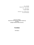
2.3 Booting
•
To boot the system, depress the power button S1 – See Photo below:
•
During the booting process, a RED LED (D1) will be blinking on the underside of
the main board. The LED will remain permanently lit once the display has been
initialized. (boot-up time about 20 seconds)
With factory settings unchanged, the default demo script saved in NAND will run
on the display.
•
---------------------------------------------------------------------------------------------------------------------Page7 / 37
V-DUO Development Kit User ManualT4 REV. 1.1
Copyright ©2008 DENSITRON TECHNOLOGIES plc.
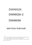
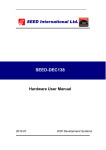
2.4 Boot sequence
The system will first boot from NAND as default and then try to mount the micro SD card
connected. Next, it will look for, and attempt to mount a USB pen drive. If neither media
is present, then it will run the default demo from NAND.
POWER ON
DATA SOURCES
TMS320DM355
internal boot ROM
RBL
UBL
NAND flash, SD card
or UART (NAND flash is the
U-boot
default device)
Linux Kernel
Linux filesystem
NAND flash, SD
card or USB drive
V-DUO Softvares
loaded at runlevel 3
Alternatively, the system can boot from UART or SD card, as long as it contains the Linux
style file system (EXT3) and the ‘bootargs’ settings are modified to boot from SD card (or
UART). Please note that we do not recommend this operation unless the user has
adequate experience, as the UBL and U-boot could be damaged.
---------------------------------------------------------------------------------------------------------------------Page8 / 37
V-DUO Development Kit User ManualT4 REV. 1.1
Copyright ©2008 DENSITRON TECHNOLOGIES plc.
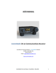
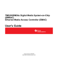
2.5 ’Demo’ Bash script operation
As shown in the previous flowchart, at the end of the boot-up sequence, the system
loads the V-DUO software. This takes place at run level 3 in the Linux system. If the user
wants to use proprietary software or update the existing SW, this is achieved as shown in
the flowchart below. The system will try to load a Bash shell script (/upload.sh) from the
SD card or USB pen drive. This script file needs to be a UNIX style text file and placed in
the root directory of the removable media. The following file systems are supported on
removable media: VFAT, EXT3. If the system does not find this file then it continues
loading the default demo software.
Linux
RUN LEVEL 3
Load V-DUO Kernel
module driver from
NAND flash
Start demo Bash script
from onboard NAND flash
Is SD card
present?
Y
Mount SD card to
Linux filesystem
Y
Mount USB drive to
Linux filesystem
N
Is
USB drive
present?
N
Is
upload.sh file
present in the root
directory of mounted
device?
N
Y
Start upload.sh Bash
script
Continue demo script
from onboard NAND flash
---------------------------------------------------------------------------------------------------------------------Page9 / 37
V-DUO Development Kit User ManualT4 REV. 1.1
Copyright ©2008 DENSITRON TECHNOLOGIES plc.
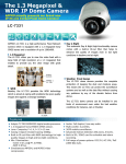
2.6 Software start-up sequence
The following flowchart shows the start-up sequence of the V-DUO software.
As shown in the flowchart, the system retrieves the display type identifier stored in
NVRAM on the transition board; therefore it’s important that the correct transition board
is used. The software is based on a dynamic modular structure for easy display
adaptation and optimisation. ’displays.config dat’ contains the main parameters for all
supported displays (see appendix for more info), this file selects the relevant initialisation
script for the display and selects the dynamic loaded library which contains display
specific binary functions like the pipe function which copies display data from various
buffers.
Load CMEM Kernel
module driver
DATA SOURCES
Start V-DUO
software
TB card NVRAM
Load display type
displays.config.dat
file
Load display
parameters
Init script file
Load and run init
script
selected by
display.config.dat file
Display specific dynamic
loaded library
Load display
specificStart main timed
thread
Start main timed
thread
Is demo_script file
present in the root
directory of SD card or
USB drive?
N
Load demo.scr file from
onboard NAND flash like
demo script
Y
Load demo_script file
from external device like
demo script
Demo script
processing
---------------------------------------------------------------------------------------------------------------------Page10 / 37
V-DUO Development Kit User ManualT4 REV. 1.1
Copyright ©2008 DENSITRON TECHNOLOGIES plc.
2.7 Software structure
As the following drawing shows, the software can use several threads and drivers. The
default method is a Main timed thread running as defined in the demo script, but this
flow can be modified by touch screen inputs, buttons presses, the PC interface or, power
monitoring system.
INPUTS
Demo script
processing
MPEG4 playback
PC USB interface
JPEG displaying
VDUO driver
Main timed thread
Video capture from
composite input
V-DUO buttons
I2C driver
Touch demo
Display
Touchscreen
Power monitoring
Power button
Pipe function stored in
display specific dynamic
loaded libraries
PIC uController
SPI interface to
display
Power switches
control
Power supplies and
power switches
---------------------------------------------------------------------------------------------------------------------Page11 / 37
V-DUO Development Kit User ManualT4 REV. 1.1
Copyright ©2008 DENSITRON TECHNOLOGIES plc.
2.8 Demo script syntax
For demonstrating the V-DUOs features, a simple demo script language was defined and
is detailed below. A file named ’demo_script’ must be saved in the root of the SD card or
as ’demo.scr’ in NAND flash. The demo_script file on SD card will only be loaded if the SD
card was in its socket during booting.
Command
PLAY_VIDEO
Parameter
Filename
SHOW_JPEG
CAPTURE_START
Filename
CAPTURE_STOP
DELAY
dddd
DELAY_INF
TOUCH_CALIBRATION
TOUCH_DRAW_ENABLE
TOUCH_DRAW_DISABLE
//
Description
Plays an MP4 video file. The next command
will only be executed when the file ends.
Shows a JPEG file
Starts capturing from the composite video
input. This command must be followed by a
DELAY command to avoid the next command
in the script being executed immediately. If
no composite video signal is detected or the
format invalid, video capture will not start.
Stops composite video capture, if running
Creates a delay of duration dddd
Maximum - 4 digit decimal value.
Infinite wait command
Starts the touch calibration sequence
Enables the touch_draw demo. After this
command each touch input will be shown as
a colour pixel on the display.
Disables the touch_draw demo
After these characters, comments can be
placed in the script
PLAY_VIDEO and DELAY commands can be interrupted by a key press or touch screen
input, except when the touch draw demo is running, in which case the command is only
interrupted when a touch is detected in the upper left-hand corner of the display. The PC
software can also interrupt the script.
Filename parameter is the name of media files with full path in V-DUO linux file system
space is not supported in filenames. Mounted removable devices root directory named as
/mnt/ (devices mounted to this directory of linux file system).
---------------------------------------------------------------------------------------------------------------------Page12 / 37
V-DUO Development Kit User ManualT4 REV. 1.1
Copyright ©2008 DENSITRON TECHNOLOGIES plc.
2.9 Initialisation script syntax
The initialisation script can be executed in two ways:
• By default at start-up. The default initialisation script file name and location
are defined in the ’displays.config dat’ file.
• Via PC software, in this case the script will start running as soon as the PC
application starts running.
Using this script requires a certain level of knowledge and experience with this
system and the display. Misuse could potentially lead to device damage.
Command
0xXX
C
D
ENA_[3V3, DCIN, VLED]
DIS_[3V3, DCIN, VLED]
PWM 0xXX
SET_[GIO0, GIO1, GIO2, CS, RES]
CLR_[GIO0, GIO1, GIO2, CS, RES]
SPI 0xXX 0xXX
DELAY 0xXX
BLANK
FB_DIS 0x0X
FB_ENA 0x0X
FB_ PAR 0xXX 0xXXXX
LOAD 0x0X
SAVE 0x0X
//
Description
Sends two hexadecimal characters XX to the PMOLED
interface as a byte.
Change PMOLED interface to command mode
Change PMOLED interface to data mode
Enables selected supply voltage
Disables selected supply voltage
Sets PIC PWM output. This output controls the VLED
DC/DC converter output voltage. XX represents a two
digit hexadecimal value
Sets selected pin to Logic 1.
Sets selected pin to Logic 0.
Sends SPI command to the display via the on board PIC
microcontroller. Both parameters are hexadecimal
digits, the parameters are sent as separate bytes, the
first parameter to follow the command is sent first. 16
and 17 bit format supported (depending on display
type). The type is defined in the displays.config.dat file
Waits XX ms. XX is a two digit hexadecimal value
Fills the display buffer with a blank image
Disables the frame buffers (0-3)
Enables the frame buffers (0-3)
Sets frame buffer parameters. The first parameter to
follow the command is taken as the unique ID number
of the frame buffer parameter to be sent, see table in
appendix, the second parameter is the value to be
assigned to that frame buffer parameter.
Load settings of frame buffer (0-3)
Save settings to frame buffer (0-3)
After these characters, comments can be placed in the
script
An example initialisation script is shown in section 3.1.5
---------------------------------------------------------------------------------------------------------------------Page13 / 37
V-DUO Development Kit User ManualT4 REV. 1.1
Copyright ©2008 DENSITRON TECHNOLOGIES plc.
2.10 System files and Directories
Name of directory or file on V-DUO file
system
/mnt/
/opt/vduo/driver/vduo.ko
/opt/demo
/opt/vduo/vduosw/vduosw
/opt/vduo/vduosw/demo.scr
/opt/vduo/vduosw/configfiles/displays.config.dat
/opt/vduo/vduosw/configfiles/
/opt/vduo/ vduosw/libs/
/opt/vduo/video/
/opt/vduo/jpeg/
Name of files on removable media
\demo_script
\upload.sh
\video
\jpeg
Description
Directory where the removable media
file system is mounted in the system
The V-DUO kernel driver
This is a bash script which runs
upload.sh and demo software from SD
card or USB device if connected. If the
console interface is required, then file
‘demo’ needs to be renamed or moved
to another location.
V-DUO demo software
Onboard demo script for V-DUO SW
Display configuration file
initialisation script folder
Dynamic loaded libraries for displays
folder
Video file directory - onboard NAND
flash
JPEG file directory - onboard NAND
flash
Description
Demo script for V-DUO SW. V-DUO
software loads this script if present
instead of onboard version (demo.scr)
System runs this file if present at startup
This folder contains the MPEG4 videos.
This folder contains the JPEG images.
---------------------------------------------------------------------------------------------------------------------Page14 / 37
V-DUO Development Kit User ManualT4 REV. 1.1
Copyright ©2008 DENSITRON TECHNOLOGIES plc.
3 V-DUO PC software
The PC software supplied on the CD-ROM includes the V-DUO PC SOFTWARE application.
The tabs on the Graphical User Interface allow the following:
Displaying JPEG images
Playing MPEG4 video files
Mixed JPEG and MPEG4 slideshows, with adjustable delay
Adjust the display’s brightness
Capture video from the composite video input
Adjust the capture position - digital pan
Touchscreen calibration and demo
Direct access to display driver IC registers
The application is Windows Vista and XP/2000/98 compatible. The application
communicates with the V-DUO system via a virtual serial COM port over USB.
The latest windows device driver can be downloaded from:
http://www.ftdichip.com/Drivers/CDM/CDM%202.04.06%20WHQL%20Certified.zip
The application communicates via a USB cable between the mini USB connector J11 on
the V-DUO and the USB port on the PC. Installing the driver at the beginning of this
chapter allows a virtual serial port to be created in device manager.
To use the application, first ensure that the V-DUO is powered up and has fully booted
(Boot LED is not blinking, but permanently ON).
Select the appropriate COM port - Device manager in control panel can be used to
identify which COM port the V-DUO is connected to.
We suggest using a COM port lower than 15. If the default COM port assigned is higher
than COM15, following the procedure below to change it:
Go to Control panel
System
Device manager
Port (COM & LPT)
USB Serial Port
Right click USB serial port to access the properties
Then go to the PORT SETTINGS tab
Then in Advanced settings, change the COM port assignment to
a number less than COM15 (preferably an unused port)
This completes the configuration change. Unplug and re-connect
the USB host cable at least twice
---------------------------------------------------------------------------------------------------------------------Page15 / 37
V-DUO Development Kit User ManualT4 REV. 1.1
Copyright ©2008 DENSITRON TECHNOLOGIES plc.
The COM port can now be seen and selected in the drop down menu on the Controls tab.
Click the connect button. When the device is connected, the Connect button becomes the
Disconnect button. This is confirmation that you are connected to the V-DUO. Make sure
that you click the Disconnect button on the Controls tab before unplugging the USB host
cable.
The application has the following tabs: Controls, Media control, Slide show, Board
information, Script Editor and About. The following sub-sections describe each of the tabs
and their usage.
---------------------------------------------------------------------------------------------------------------------Page16 / 37
V-DUO Development Kit User ManualT4 REV. 1.1
Copyright ©2008 DENSITRON TECHNOLOGIES plc.
3.1 Controls tab
As well as connecting to the COM port, the Controls tab allows display brightness
adjustment in 64 steps, and the ability to adjust the capture area (or capture position) of
the composite capture feature on the media control tab.
The capture port captures at a resolution of 632x512, some displays have a lower
resolution than the capture port.
For example, a 4.3” AMOLED display only has a resolution of 480x272 and hence only
capable of showing 480x272 of the available 632x512 (capture resolution). The capture
horizontal and vertical sliders allow panning of the capture buffer.
---------------------------------------------------------------------------------------------------------------------Page17 / 37
V-DUO Development Kit User ManualT4 REV. 1.1
Copyright ©2008 DENSITRON TECHNOLOGIES plc.
3.2 Media Control tab
This tab allows the playing of JPEG and MPEG 4 files stored in the JPEG and VIDEO
folders (respectively) in the SD CARD or USB pen drive and NAND flash. The default is
NAND, if the system is booted without an SD card or USB device connected on start-up.
Simply select the desired file from the drop down menu and click on the ‘show selected
picture’ or ‘play selected video file’ button.
Clicking the ‘Start composite Capture’ button starts the capture of a valid composite
video signal from the composite video input and displays it on the screen. If no
composite video signal is detected or the format invalid, video capture will not start.
As explained in the previous section, the Horizontal and Vertical position sliders in
controls tab adjust the capture area to be displayed.
Clicking the ‘Start touch calibration’ button initiates a 3 point touch screen calibration
process.
Calibration starts with a white dot appearing in the top left-hand corner. Using an
adequate stylus, touch and maintain contact with the white dot until it moves to the
bottom Right corner. Touch the white dot again until it moves to the top right corner.
Touching the 3rd dot completes the calibration process.
Start touch demo initiates a touch screen demo where the pixel directly underneath the
touch stimulus is illuminated in yellow. Before starting the touch demo, a suitable image,
with a dark background, should be selected from the drop down menu and displayed.
The ‘Stop all’ button stops all activities features.
The 'Resume onboard demo’ button runs the Demo script in the SD CARD, USB pen drive
or NAND flash. When an SD card is connected, the demo script from the SD card will run
as the SD card has boot priority, followed by USB then the internal (NAND) memory.
---------------------------------------------------------------------------------------------------------------------Page18 / 37
V-DUO Development Kit User ManualT4 REV. 1.1
Copyright ©2008 DENSITRON TECHNOLOGIES plc.
3.3 Slide show tab
This tab is used for creating a slide show, which can consist of a mixture of JPEG and
MPEG4 files stored in the SD CARD or USB pen drive and NAND flash.
Video and JPEG files are added to the list of files to be shown in the demo by selecting
the desired file in the drop down menu and clicking on ‘Add video file’ or ‘Add JPEG file’
respectively.
Selecting a file and then clicking ‘delete from list’ will remove that file from the list. Lists
can also be saved to and loaded from your PC as a demo list (text file) by clicking the
‘Save list to file’ and ‘Load list from file’ buttons respectively.
The ‘Save as demo’ button is slightly different, in that it saves the list as a ‘demo_script’
on the PC. This file can then be moved to the SD card or USB device, as a ‘demo_script’,
which means the script can be used to replace the default demo that starts on boot-up.
The slide show is initiated by clicking ‘Start slide show’. The button then becomes ‘Stop
slide show’, click this button to stop the slide show.
3.4 Board information tab
This window contains information on the Display connected and software versions.
---------------------------------------------------------------------------------------------------------------------Page19 / 37
V-DUO Development Kit User ManualT4 REV. 1.1
Copyright ©2008 DENSITRON TECHNOLOGIES plc.
3.5 Script editor tab
This is an editor, where the display registers can be accessed and modified. This script
editor uses the same structure of commands as the Initialisation script syntax (please
refer to section 2.9).
See section 6.4 for examples on modifying the initialisation script on 3.5” and 4.3”
AMOLEDs.
3.6 About tab
This tab holds information on the V-DUO PC software version and release date.
Note: With some displays (typically 3.5” or larger) the PC USB cannot support the VDUO’s power requirements if the battery is completely discharged and the power supply
is not connected.
If you experience difficulty in connecting to the kit, connect the DC IN power supply to
power the V-DUO system.
---------------------------------------------------------------------------------------------------------------------Page20 / 37
V-DUO Development Kit User ManualT4 REV. 1.1
Copyright ©2008 DENSITRON TECHNOLOGIES plc.
4 Script editing
All V-DUO scripts are simple text files, but bash scripts need UNIX style ‘end of line’
(EOL) characters, which is different to those used with windows. Therefore a text editor
is required which can also support UNIX style text files. Below is a link to a suitable
editor:
http://codertools.fileburst.com/TotalEdit_install_5_0_8.msi
4.1 Creating a demo script
The default demo that runs on boot up can be modified by editing the ‘demo_script’ file
saved in the root of the desired SD CARD or USB pen drive.
4.1.1 Creating JPG and MPEG4 (streams P and I only)
slideshows
1. Insert the SD card into a PC SD card port or SD card reader
2. To add images, Copy the required images to the folder "jpeg" in the SD card.
a. Open the demo_script file with the "totaledit" or any Unix style text
editor.
b. Edit the demo_script i.e by adding -> "SHOW_JPEG
/mnt/jpeg/image_name.jpg”. an example is shown at the end of the next
section.
3. To add Video files (already encoded for V-Duo/TMS320DM355), Copy the video
file to the folder "video" in the SD card.
a. Open the demo_script file with the "totaledit" or any Unix style text
editor.
b. write in the demo_script "PLAY_VIDEO" /mnt/video/video_name.mpeg4
4. Save and close the demo_script file.
5. Reboot as described above, and the images and videos will be shown
automatically in the default demo application.
4.1.2 Adding a delay
The list of files in demo_script can include a combination of video and image files and
these will be played in the order listed.
To add a delay between the images, add the text "DELAY 10" for a 10s delay in the
demo_script, in between the two images where the delay is required.
Below is an example of a demo_script file:
// Example demo script for V-DUO board
PLAY_VIDEO /mnt/video/speedr.mpeg4
SHOW_JPEG /mnt/jpeg/b1.jpg
DELAY 5
SHOW_JPEG /mnt/jpeg/b5.jpg
DELAY 5
SHOW_JPEG /mnt/jpeg/b6.jpg
DELAY 5
SHOW_JPEG /mnt/jpeg/b7.jpg
DELAY 5
---------------------------------------------------------------------------------------------------------------------Page21 / 37
V-DUO Development Kit User ManualT4 REV. 1.1
Copyright ©2008 DENSITRON TECHNOLOGIES plc.
4.1.3 Capturing video from the composite video input
Note: The list of files in demo_script must first be deleted in order to avoid the demo
running pictures and video files.
1) Add the following command to the demo_script:
“CAPTURE_START” - Please note that the command is case sensitive.
“CAPTURE_STOP” – will stop the video capture.
2) Save and close the file.
3) Reboot and the system will automatically, continuously capture whatever is on the
composite and this will be shown on the display.
Below is an example of a demo_script file capturing video:
// Example demo script for V-DUO board
CAPTURE_START
DELAY 180
// 3 minute delay
CAPTURE_STOP
4.1.4 File transfer
Files can be transferred to the V-DUO by USB pen drive or Micro SD card. These are safe
modes of operation as they can reduce the risk of the system files in the onboard NAND
flash getting corrupted.
It is possible to transfer files from the Micro SD card to NAND flash via upload.sh. The
script will need to be edited by adding a copy command.
For example if we want to copy \sample.mpeg to NAND flash, we need to add the
following line in upload.sh using a text editor:
cp /mnt/sample.mpeg /opt/vduo/video/
4.1.5 Register changes (driver IC on display)
Any register settings can be changed by editing file “P0403” in the folder "configfile using
the "totaledit" text editor or any Unix style text editor.
ALL register commands are sent over the SPI bus via the PIC microcontroller.
Simply type "SPI 0x01 0x00" (the first hex value to follow the command is taken as the
register to be edited and the second hex value is the data to be written).
Below is an example of register being configured in P0403:
---------------------------------------------------------------------------------------------------------------------Page22 / 37
V-DUO Development Kit User ManualT4 REV. 1.1
Copyright ©2008 DENSITRON TECHNOLOGIES plc.
4.1.6 MPEG4 Transcoding
The V-DUO system supports MPEG4 Simple Profile levels 0,1,2,3 with I and P frames
only. The maximum supported resolution is HD 720p (1280x720) and SXVGA
(1280x960). The system is capable of playing back video files which have been encoded
for the TMS320DM355. The encoder used in the V-DUO is the Texas Instrument
TVP5146. Another option is to transcode video files with ArcSoft Media converter, which
can be downloaded from:
http://www.arcsoft.com/public/software_title.asp?ProductID=14&dyContent=LANG_DOW
NLOAD
The screenshot below shows the default settings for transcoded video files:
The settings above can be adjusted in order improve the quality of the transcoded video
file.
---------------------------------------------------------------------------------------------------------------------Page23 / 37
V-DUO Development Kit User ManualT4 REV. 1.1
Copyright ©2008 DENSITRON TECHNOLOGIES plc.
5 Hardware
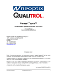
5.1 Power supply architecture
The system can be powered by DC IN, *USB or Li-ion Battery.
*With some displays (typically 3.5” or larger) the PC USB cannot support the V-DUO’s power requirements if
the battery is completely discharged and the power supply is not connected. If you experience difficulty in
connecting to the kit, DC IN power supply to power the V-DUO system.
The system will automatically charge the battery from whatever power source is
connected, USB or DC IN.
The block diagram below shows the V-DUO power supply architecture.
TPS65053
AC/DC wall adapter
BQ24030 intelligent
power path and
battery charger
DCDC converter
1,8 V
DDR2 Memory
DCDC converter
1,3 V
TVP5146
Composite interface
VDCIN
PSTATUS
Li-ION Battery
TMS320DM355
DMsoC
3V3
USB slave port
DCDC converter
3,3V
POWER_ENA
NAND flash
SD Card interface
PIC uController
DCDC converter
5V
Power button
Control signals
USB host port
DC_ENA
Power switch
OLED_ENA_VCC
Power switch
Display interface
Power signals
PWM
VLED_ENA
DCDC converter
5->27 V
VACIN
HPD
---------------------------------------------------------------------------------------------------------------------Page24 / 37
V-DUO Development Kit User ManualT4 REV. 1.1
Copyright ©2008 DENSITRON TECHNOLOGIES plc.
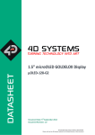
5.2 Outline and Connector placement drawing
J12
J13
J15
J14
J9
J2
J11
J5
J4
J3
J10
J6
J1
---------------------------------------------------------------------------------------------------------------------Page25 / 37
V-DUO Development Kit User ManualT4 REV. 1.1
Copyright ©2008 DENSITRON TECHNOLOGIES plc.
5.3 Connectors pin out
J1 – MICROSD SOCKET
This socket supports Micro SD cards with up to 2 Gb of memory.
Pin Nr.
1
2
3
4
5
Signal name
DAT2
CD/DAT3
CMD
VDD
CLK
Pin Nr.
6
7
8
9
10
Signal name
VSS
DAT0
DAT1
C DETECT
GND
J2 – VIDEO IN
This is the composite video input connector. Expected signal levels are 1Vp-p
Pin Nr.
1
Signal name
AIN
Pin Nr.
2
Signal name
AGND
J3 – OLED A
This is the PM OLED interface, compatible with the original USB06 DUO kit.
Pin Nr.
1
2
3
4
5
6
7
8
9
10
Signal name
D0
D1
D2
D3
D4
D5
D6
D7
RD
WR
Pin Nr.
11
12
13
14
15
16
17
18
19
20
Signal name
CD
CS
GND
GND
VLED
GND
GND
GND
VCC
VCC
J4 – OLED B
This is the PM OLED interface, compatible with the original USB06 DUO kit.
Pin Nr.
1
2
3
4
5
6
7
8
9
10
Signal name
GIO0
GIO1
GIO2
NC (GIO3)
NC (GIO4)
NC (GIO5)
AC IN
NC (GIO7)
RD
VLED ENA
Pin Nr.
11
12
13
14
15
16
17
18
19
20
Signal name
VLED PWM
SCL
SDA
RES
HPD
NC (KEY)
GND
GND
VCC
VCC
---------------------------------------------------------------------------------------------------------------------Page26 / 37
V-DUO Development Kit User ManualT4 REV. 1.1
Copyright ©2008 DENSITRON TECHNOLOGIES plc.
J5 – AMOLED
This is the AM OLED and TFT interface. For AMOLEDs HSYNC, VSYNC and CLK are not
used. Also note that for AMOLEDs, display data is sent over the parallel RGB interface
(pins 1 to 25), whilst initialisation commands and control data is sent over the SPI bus
(pins 27 to 29).
Pin Nr.
1
2
3
4
5
6
7
8
9
10
11
12
13
14
15
16
17
18
19
20
Signal name
R7
R6
R5
R4
R3
R2
G7
G6
G5
G4
G3
G2
B7
B6
B5
B4
B3
B2
HSYNC
VSYNC
Pin Nr.
21
22
23
24
25
26
27
28
29
30
31
32
33
34
35
36
37
38
39
40
Signal name
GND
CLK
GND
GND
OE
NC
SPI CS
SPI CLK
SPI DAT
XCLK OUT1
YCLK OUT2
X+
CLK OUT3
YGND
GND
DCIN SW
DCIN
J6 – EXTENSION
This is an interface reserved for future development, for example, new displays.
Pin Nr.
1
2
3
4
5
6
7
8
9
10
11
12
13
14
15
16
17
18
19
20
Signal name
A13
A12
A11
A10
A9
A8
A7
A6
A5
A4
A3
A2
A1
A0
BA1
BA0
D15
D14
D13
D12
Pin Nr.
21
22
23
24
25
26
27
28
29
30
31
32
33
34
35
36
37
38
39
40
Signal name
D11
D10
D9
D8
D7
D6
D5
D4
D3
D2
D1
D0
CE1
WE
OE
WAIT
ADV
INT
CLK
INT2
---------------------------------------------------------------------------------------------------------------------Page27 / 37
V-DUO Development Kit User ManualT4 REV. 1.1
Copyright ©2008 DENSITRON TECHNOLOGIES plc.
J7 – PIC PGM
This interface is used for re-programming the PIC microcontroller if required. The PIC
decodes the touch screen and sends data to the display driver IC via SPI. The
microcontroller also carries out power management and passes all SPI commands to the
display driver IC. The PIC communicates with the TMS320DM355 using I2C.
See section 2.7 for more detail on the SW functionality of the PIC.
Pin Nr.
1
2
3
Signal name
SCLK
SDAT
MCLR
Pin Nr.
4
5
Signal name
PIC VCC
GND
J8 – ALTERA CPLD PGM
An Altera EPM3032 CPLD is used for PMOLED and USB address decoding. This interface is
used for programming the CPLD.
Pin Nr.
1
2
3
Signal name
TCK
TDO
TMS
Pin Nr.
4
5
6
Signal name
TDI
GND
VCC
J9 – TTL UART
This interface is used to connect the system to a PC. A UART to USB connector board is
required in addition to a console application i.e. HyperTerminal
Pin Nr.
1
2
Signal name
RXD
TXD
Pin Nr.
3
4
Signal name
GND
+3,3V
J10 – USB
This USB port is used for connecting a USB pen drive. This media is an alternative to the
Micro SD card. To mount the USB pen drive on the video and run the demo, the memory
device (pen drive) should contain the entire contents of the Micro SD card, as originally
supplied. On start-up, the system will first try to mount the Micro SD, and then USB.
Pin Nr.
Signal name
Pin Nr.
Signal name
1
VBUS
3
D+
2
D4
GND
J11 – MINI USB
This interface is for connecting the V-DUO to a PC USB port in order to use the V-DUO
Windows application.
Pin Nr.
Signal name
Pin Nr.
Signal name
1
VBUS
4
ID
2
D5
GND
3
D+
---------------------------------------------------------------------------------------------------------------------Page28 / 37
V-DUO Development Kit User ManualT4 REV. 1.1
Copyright ©2008 DENSITRON TECHNOLOGIES plc.
J12 – DC IN
5V DC, 2A, centre positive, power supply input.
Pin Nr.
1
2
Signal name
POWER+
POWER-
Pin Nr.
3
Signal name
NC.
J13 – BATTERY
The battery interface is designed to support
Pin Nr.
Signal name
1
BATT+
2
BATT+
3
BATT-
a 3.6V Li-ion Battery.
Pin Nr.
4
5
6
Signal name
BATT+5V
GND
J14 – KEYPAD/BUTTON Interface
This interface is group of 6 GPIOs dedicated to keypad or button connection. The pins are
normally pulled high. They are controlled by the GPIO configuration registers in the
TMS320DM355 processor.
Pin Nr.
1
2
3
4
Signal name
BUTTON0
BUTTON1
BUTTON2
BUTTON3
Pin Nr.
5
6
7
8
Signal name
BATT+5V
GND
GND
J15 – TOUCH Interface
This interface gives access to the analogue touchscreen connections. The part number for
the mating connector is AMP – 7-215083-4.
Pin Nr.
1
2
Signal name
XY-
Pin Nr.
3
4
Signal name
X+
Y+
5.4 DC Characteristics
Parameter
Input voltage from AC/DC wall adapter
Input voltage from USB slave port
VLED output for PMOLED displays
Maximum current from ACIN
Maximum current from USB slave power
Maximum current from battery
Maximum current from DCIN (BQ24030)
output
Maximum current from OLED_VCC
Maximum current from DCIN by display
Sleep current without display
Current consumption without display
Symbol
V_ACIN
V_USBIN
VLED
-
Min.
4,4
4,4
5
-
Typ.
5
5
-
Max.
16
6
27
2
500
2
2
Unit
V
V
V
A
mA
A
A
TBD
TBD
600
1,7
mA
A
mA
mA
---------------------------------------------------------------------------------------------------------------------Page29 / 37
V-DUO Development Kit User ManualT4 REV. 1.1
Copyright ©2008 DENSITRON TECHNOLOGIES plc.
Appendix
6 Appendix
6.1 Description of displays.config.dat :
This file contains the general description for different displays. The file is made up of
sections. The syntax used to define and declare a section is as follows:
SECTION_NAME
{
…
}
Sections contain several fields:
Field name
NAME
DISPLAY_TYPE
DRIVER_TYPE
CONTROL_IF
DATA_IF
COLOR_DEPTH
MIN_VLED
MAX_VLED
X_RES
Y_RES
INIT_FILE_NAME
WRITE_DLL
DEFAULT_DEMO
TOUCH
CTRL_INF
Description
Display name - max 32 char
AMOLED,PMOLED or TFT
Display driver part number - max 32 char
Control interface type, comma separated words.
Supported types: [SPI8, SPI16, SPI17, PMOLED, VPBE]
Data interface type :
Supported types: [PMOLED, VPBE, EXT]
Display colour depth - in bits per pixel
Minimum value of PWM which controls the VLED DCDC
converter
Maximum value of PWM which controls the VLED DCDC
converter
Horizontal resolution of display - in pixels
Vertical resolution of display - in rows
Name of display init file with path - max 256 char
Name of display access library file with path - max 256 char
Name of default demo script file with path - max 256 char
Touch supported YES or NO
Control information string for PC software - max 256 char
Sections are configured based on the display ID retrieved from the transition board
NVRAM. Example of a section definition:
DISPLAY_ID(100){
MIN_VLED=0
MAX_VLED=256
X_RES=480
Y_RES=272
INIT_FILE_NAME=./configfiles/P0430.ini
WRITE_DLL=./libs/P0430.so
DEFAULT_DEMO=./demo.scr
TOUCH=YES
CTRL_INF=ISPI 0x3E 0xhh; [f=hc; d=80; min=00; max=FF;]
}
---------------------------------------------------------------------------------------------------------------------Page30 / 37
V-DUO Development Kit User ManualT4 REV. 1.1
Copyright ©2008 DENSITRON TECHNOLOGIES plc.
6.2 Framebuffer parameters
Each frame buffer parameter in the initialisation script has a unique hex number. The
following table details their assignment. Additional information on the frame buffer
parameters can be found at:
http://focus.ti.com.cn/cn/lit/ug/spruek9/spruek9.pdf
Number
0x00
0x01
0x02
0x03
0x04
0x05
0x06
0x07
0x08
0x09
0x0A
0x0B
0x0C
0x0D
0x0E
0x0F
0x10
0x11
0x20
0x21
0x22
0x30
0x31
0x32
0x40
0x41
0x42
0x50
0x51
0x52
Description
Video mode: 0- non interlaced; 1 –interlaced
Horizontal resolution - in pixels
Vertical resolution - in rows
Left margin - in pixels
Right margin - in pixels
Upper margin - in rows
Lower margin - in rows
Hsync length - in pixels
Vsync length - in rows
Frames per sec setting (it is used for mode detection, only if standard
mode is used)
Sync
Standard mode flag. 0 if non-standard mode selected
basepx
basepy
Virtual horizontal resolution
Virtual vertical resolution
Bits per pixel
0 - activate now
Offset of red bits
Length of red bits
0 if MSB of red bits left
Offset of green bits
Length of red bits
0 if MSB of green bits left
Offset of blue bits
Length of blue bits
0 if MSB of blue bits left
Offset of transp bits
Length of transp bits
0 if MSB of transp bits left
---------------------------------------------------------------------------------------------------------------------Page31 / 37
V-DUO Development Kit User ManualT4 REV. 1.1
Copyright ©2008 DENSITRON TECHNOLOGIES plc.
6.3 Booting whilst monitoring console messages
First Place the SD card in the V-DUO, and also connect the UART to USB cable/board
between the USB port on the PC and J9 on the V-DUO if you wish to monitor the
messages generated.
To monitor the messages generated, as well as the cable connection, you will need to run
the console application and configure it as follows:
Serial
Enter correct COM port (use device manager if required)
Set speed to 115200 bps
Then click on open radio button.
Apply power (plug in the power cable).
Don't remove the SD card without powering the system down (depress S1) or
unplugging the power cable.
The system will boot automatically and takes approximately 30 seconds to 1
minute.
6.4 Modifying AMOLED initialisation script (3.5” & 4.3”)
Below is an example showing various registers being change using the script editor tab.
---------------------------------------------------------------------------------------------------------------------Page32 / 37
V-DUO Development Kit User ManualT4 REV. 1.1
Copyright ©2008 DENSITRON TECHNOLOGIES plc.
Referring to the image on the previous page, the SPI command is followed by the
register address and the value to be written to it, both in hexadecimal. When the 'RUN'
button is clicked, register 0x3A is assigned the hex value 3F (this is sent through the PIC
microcontroller). This command will increase the overall contrast of the display to its
maximum. Upon clicking the RUN button, the contrast change is immediately observed
on the display.
The DIS_3V3 command will disable the 3V3 power supply and the screen will turn blank
(white).
To re-enable it, simply type ENA_3V3, click ‘Run’.
---------------------------------------------------------------------------------------------------------------------Page33 / 37
V-DUO Development Kit User ManualT4 REV. 1.1
Copyright ©2008 DENSITRON TECHNOLOGIES plc.
The DIS_VLED command will disable the VLED power supply (external DC-DC).
To re-enable it, simply type ENA_VLED, and click ‘Run’.
As shown above the PWM command controls the output voltage of the external DC-DC
converter used for the High voltage supply (OLED_VLED) on the PMOLED display
interface.
---------------------------------------------------------------------------------------------------------------------Page34 / 37
V-DUO Development Kit User ManualT4 REV. 1.1
Copyright ©2008 DENSITRON TECHNOLOGIES plc.
The value can range from 0x00 to 0xFF with 0x00 resulting in a DC-DC output voltage of
0V and therefore turning the display blank (black). The maximum value 0xFF results in
an output voltage of 27V.
SET_GIO0 will set the GIO0 pin. This command can also be used to set the GIO1, GIO2,
CS and RES pins.
CLR_GIO1 will clear the GIO1 pin. This command can also clear the GIO0, GIO2, CS and
RES pins.
---------------------------------------------------------------------------------------------------------------------Page35 / 37
V-DUO Development Kit User ManualT4 REV. 1.1
Copyright ©2008 DENSITRON TECHNOLOGIES plc.
In the example on the previous page, the ‘Delay 0x01’ command will insert a time delay
between executing the ‘SET_GIO0’ command after executing the ‘CLR_GIO0’ command.
The BLANK command will turn the screen completely blank (with black screen). Basically
it will clear the display buffers.
The ‘MEM’ command provides direct access to the V-DUOs internal system memory
(NAND). With this command, any internal memory address in V-DUO can be written to.
Misuse could overwrite or corrupt system files.
---------------------------------------------------------------------------------------------------------------------Page36 / 37
V-DUO Development Kit User ManualT4 REV. 1.1
Copyright ©2008 DENSITRON TECHNOLOGIES plc.
Framebuffer settings can be used to setup and select the following:
•
Select interlace video mode
•
Set display resolution
•
Set margins
•
Set Length of h and v sync
•
Set base of window
•
Set virtual resolution
•
Set bpp mode
•
Set position of RED bits
•
Set position of GREEN bits
•
Set position of BLUE bits
•
Set position of Transparency bits
Writing command FB_DIS0xXX will disable framebuffer XX.
Writing command FB_ENA0xXX will enable framebuffer XX.
Writing command FB_PAR 0xXX 0xXX - the first hexadecimal value represents the buffer
address and the second hexadecimal parameter is the value to be assigned to that buffer
address. e.g. FB_PAR 0x01 0x01E0; FB_PAR 0x02 0x0110; will set the display resolution
to 480x272.
FB_LOAD 0xXX will load configuration file XX, and FB_SAVE 0xXX will save the
parameters to configuration file XX.
---------------------------------------------------------------------------------------------------------------------Page37 / 37
V-DUO Development Kit User ManualT4 REV. 1.1
Copyright ©2008 DENSITRON TECHNOLOGIES plc.