1
Genesis One Grid Charger Operation Manual Version 2.2-1
Manual Revision 2.2-1 June11, 2012
Introduction:
Got a hybrid car with a High Voltage battery pack that is acting up?
The Genesis One universal battery charger/balancer may be the answer. This charger can
charge any battery from 7V to 240V at a constant current.
The Overnight Charger can charge at 1.05A and 350ma, and the Maintenance Charger (no
longer available) can charge at 350ma.
Charger is configurable to charge with seven different Run Modes (charge, charge/discharge or
discharge profiles), and six car profiles.
The charger has an isolated RS232 port that reports the state of the charge and other relevant
data into a remote computer for data logging. Charge parameters can be reprogrammed by the
user. Either from the charger, or from a remote PC
The hardware specific parameters and test mode are password protected.
Charger mates with custom in car harnesses, so the same charger can be used for 6 different
cars, each with a unique harness. Charging a multi cell series battery in this way has been
shown to condition the pack for better performance, and at the same time as a cell balancer to
get all of the cells to the fully charged state, and to recover from many battery related error
codes. A Discharge Load is available that plugs between the car and charger harness. It is
used with the automatic Discharge/Charge, programmable from 1 to 3 Cycles, of Run Mode 6,
which further improves this process of balancing the cells of a battery.
1
Table of Contents
Genesis One Grid Charger Operation Manual Version 2.2-1 ....................................................................1
Introduction:...............................................................................................................................................1
Care, Handling and Use of the Grid Charger:............................................................................................4
What is Displayed on Power-up: ...............................................................................................................4
Front Panel Key Functions and LED Indicator: ........................................................................................6
Keypad Keys: ................................................................................................................................... 6
LED Indicator: ................................................................................................................................. 9
Viewing Values and Parameters on the Liquid Crystal Display: ...............................................................9
Typical Operation, Starting Charging (RunMode 1 or 2): .......................................................................10
Charger models and Specifications:.........................................................................................................11
How the Grid Charger Works: .................................................................................................................12
Stopping Charging: ..................................................................................................................................12
Pausing Charging: ....................................................................................................................................13
Car Profiles ( Matching Battery Pack Charging Requirements):.............................................................13
Cut-Back Voltage: ........................................................................................................................ 14
Maximum Voltage: ......................................................................................................................... 14
Car model and year: ....................................................................................................................... 14
Run Modes:..............................................................................................................................................15
Run Modes 1** and 2: .................................................................................................................. 15
Run Modes 3** and 4: ................................................................................................................... 15
Run Mode 5, Long Term (Storage) Maintenance Charging, Low current: .................................... 15
Run Mode 6, Discharge/Charge Cycling: ...................................................................................... 17
Stop Discharging list of reasons: .......................................................................................... 19
Discharge/Charge Cycles Display:................................................................................................. 19
Disabling Automatic Stop of Discharge mode: "Slope Stop Disable" ........................................... 20
Variables and defined factors that affect this mode:............................................................. 20
Options to select before starting: ......................................................................................... 21
Run Mode 7, Pulsed Discharge, no charge current: ....................................................................... 21
Using the EDIT Function:........................................................................................................................22
Changing the Run Mode: .........................................................................................................................23
Using the SETUP Function:.....................................................................................................................23
Car Profile: ..................................................................................................................................... 24
Options: .......................................................................................................................................... 24
Brief Description and Displays for Each Option: .......................................................................... 25
Soak Period After "Voltage Plateau Detected" End of Charge, Off/On: ........................................ 25
Bank 0/1: ........................................................................................................................................ 25
Allow Charging at 10 degrees F colder than Normal Limits: ........................................................ 25
Serial Output Only During Charging or Always:........................................................................... 26
Parameters Viewing & Changing Access Level:............................................................................ 26
Password Not Entered or Incorrect: ............................................................................................... 26
Change Temperature Degrees (F or C): ......................................................................................... 27
1-minute or 5-seconds Serial reporting interval:............................................................................ 27
Charge before Discharge, Yes/No?................................................................................................ 27
Reload Defaults:............................................................................................................................ 28
2
Press STOP to end SetUp:.............................................................................................................. 28
TEST: .......................................................................................................................................................28
Serial Output: ...........................................................................................................................................30
Setup Parameters and hardware: .................................................................................................... 30
Input as well as output on the Serial Port:...................................................................................... 30
What is sent out from the Serial Port: ............................................................................................ 30
Power-on Serial Output: ....................................................................................................... 30
“Start Charging” Serial Output:............................................................................................ 30
Charge Data: ....................................................................................................................... 31
Discharge Data: .................................................................................................................... 31
Explanation and listing of the SysStatus Variable flag bits:........................................................... 32
Converting decimal to binary:........................................................................................................ 32
Serial Input: .................................................................................................................................... 33
Power Failure: ................................................................................................................................ 35
Abnormal Conditions:..............................................................................................................................35
Over-Current: ................................................................................................................................. 35
Under-Current: ............................................................................................................................... 35
Fan and Temperature Control, and Shut-down: .......................................................................................36
Notes on Cold Temperature Charging: ....................................................................................................37
Variables and Parameters List:.................................................................................................................37
Informational Parameters ............................................................................................................... 38
Setup parameters ............................................................................................................................ 38
Operating Parameters and Limits................................................................................................... 38
Protected Parameters (Tech Edit)................................................................................................... 39
Further Explanation of Operation and "chargermodes" (M1, M2..... M9): .............................................40
Parameters: ..................................................................................................................................... 40
General: .......................................................................................................................................... 40
Topping Mode: ............................................................................................................................... 40
Soak:............................................................................................................................................... 41
Accessories and enhancements:...............................................................................................................41
Discharge Load for RunMode 6 Operation:.................................................................................. 41
OBD-II State of Charge (SOC) Reset and Diagnostic Flash Code Trigger Device:..................... 42
Programming Adapter: ................................................................................................................... 42
Comments and Feedback Welcomed: ......................................................................................................45
What is New & Improved in Version 2.2 Firmware: ..................................................................... 45
Glossary: ..................................................................................................................................................49
3
Care, Handling and Use of the Grid Charger:
Read the reminder list on the right side of the Grid Charger front panel each time before preparing to use
it.
•
Always turn off the AC power before connecting or disconnecting charger from the vehicle
battery pack or any other battery pack being charged.
•
Make certain that charging has stopped before disconnecting the charger connection to the
battery. Correct sequence: STOP charger, turn off the AC power switch/disconnect the AC cord,
disconnect the battery cable.
•
Do not use this equipment where it could get wet or experience condensation.
•
Only use a properly grounded GFCI protected 3-wire AC circuit to power this charger.
•
Do not use this equipment in enclosed spaces without adequate ventilation. (If the ambient
temperature is warm to hot, to prevent overheating.)
•
Be sure, before starting a charge, that the Car Profile matches the car when using the default
settings. Pay extra attention if you have customized any settings.
•
Consult Genesis One about any unexpected behaviour not covered by this user manual.
What is Displayed on Power-up:
First the unit checks that the EEPROM version matches what is expected by the program, and displays
it:
EEPROM V 4.000
Parameters Read.
"Parameters Read." means that they match and the parameters stored in non-volatile memory, including
those changed by the user, have been read into RAM memory to use in operation. "Defaults Written" on
the second line instead would mean the unit sees a mismatch of versions and will instead take the default
values contained in the program code and load them into EEPROM memory. This happens with a new
unit at the factory, when the user activates "Restore Defaults", or when a newly updated program version
requires new or re-arranged parameter locations in the EEPROM.
After the ViewTime, the program Version Number and Date is displayed:
Prod Gridcharger
V 2.2 Code 05/01
Then the previously selected Car Profile information is displayed and finally, the Off- mode display,
initially set to show Battery Volts and Charging Current on the top and bottom LCD lines, respectively.
Only on power-up after an upgrade from version 1.2, you will then hear a distinct series of beeps and
see the message:
Doing AutoPStest
Do Not Disturb!!
The Grid Charger will now measure and record the Voltage output of all, and then each one, of the
power supplies. This will take about two minutes, and you will be able to see the progress up to step 7
on the LCD. Be sure that the charger is disconnected from the battery and do not press any key or
turn off the charger, until this has completed.
4
User Operating Instructions: Grid Charger
Overnight 1.05 Amp "High" Current** and Maintenance 350mA Low Current models
June 11, 2012
Program Version 2.2 (** indicates "Overnight charger model only")
Front Panel Key Functions and LED Indicator:
Keypad Keys:
Press this key to Start Charger operation. (Charger behaviour at this time depends on the Run Mode
selected & the charge characteristics of the Car Profile choice & its programming. See "Run Modes:"
and "Car Profiles..." below for details.)
Note: [START] will also end/over-ride other modes such as Test (Tech) mode.
When the STOP key is pressed:
If charging: Stops/ends/cancels charging for all Run Modes.
If Editing a parameter: Aborts/exits without saving changes (If pressed before [EDIT] was pressed for
the second time to store the changed value.)
5
If in Setup: Ends/Exits Setup and resets pointer to the first item (CarProfile), for the next time.
If in Test (Tech) mode: Stops/resets the Test mode and returns unit to normal standby/Off mode
If charging: Suspends charging (power supplies turned off) but retains the time charging and MilliAmpHours accumulated up to this point and the Voltage at the start of charging. Press Pause again or START
to resume charging with this data continuing to advance from the point it was paused.
If in Test (Tech) mode: Turns off the power supply(s) being tested and retains the place in the Test
sequence, ready to resume at the same place when START is pressed to resume.
Turns on or off audible alerts (alarms) for events: Over & Undercurrent, Discharge rapid sampling,
and AutoStop reminder beeps. Audible alerts function Powers up "On". For Over and Under current
alarms, it controls the LCD display of the alarm as well as the audible (beeper). When AutoStop
reminder is sounding, pressing this key (during the pauses between the beeps) will silence it.
First press, editing: Switches display from DATA display to DATA edit.
Second Press, editing: Saves the change and returns to DATA display.
When Charging, the first press switches the 2nd line display to "one parameter" display for
viewing/editing, with Car Profile selected. Then the edit key functions as above.
See "Using the EDIT Function" below.
in EDIT:
Increment data (increase the value by one, at the cursor position)
in regular DISPLAY: Switch to top line of display for selecting data to display
in Discharge/charge Cycles Display: Changes page
in Charging: Toggles between the 2 available LCD charging display pages
in Charging: Toggles between the 2 available LCD charging display pages
in EDIT:
Decrement data (decrease the value by one, at the cursor position)
in regular DISPLAY: Switch to bottom line of display being active for selecting data to display
in Discharge/charge Cycles Display: Changes page
in SetUp: Toggles 2-choice items - Soak No/Yes, Discharge Data Storage in Bank 0/1, Cold Charge
No/Yes , Serial Always No/Yes, User/Tech level access, F/C degrees, Pre-Charge Yes/No
6
in Test (Tech): Turns off PCCHI power supply** (** indicates "Overnight charger model only")
in EDIT:
move edit field one digit right
in DISPLAY: scroll right for the next data item to display
in EDIT: move edit field one digit left
in DISPLAY: scroll right for next data to display
Press to select Setup Function or move to the next Setup item in the rotation. See "Using the SETUP
Function:" below.
Press to select RUN MODE choice (editing). The current Run Mode will be displayed on the bottom
line of the LCD and can then be edited like the other parameters. This is a "shortcut" key provided as a
quicker way to select Run Mode for editing than by scrolling. See "Using the EDIT Function" below.
Press to select Test Function and point to the next Test pattern in the sequence. The first
one switches all the power supplies on. Each subsequent press of TEST will move to the next Test step.
If PAUSE is pressed during Test, the power supply(s) will be turned off and the position in the sequence
remembered. Press START to resume testing at the same step as before when PAUSE was pressed
If a key is not interpreted or active in the charger's current mode of operation or in the User Access
Level, usually, a beep and a message like the following will warn about this and no action occurs:
In some situations, such as during Editing, a long "Bad" beep will instead be used to warn that a key is
inappropriate and will not be processed.
Repeat Action: In most modes of operation, holding one of the Arrow Keys (Up, Down, Left or Right)
7
pressed will cause a repetition of that key's action for as long as it is pressed. This can be used to easily
scroll quickly through a selection or change a value.
LED Indicator:
On - Red, during charging until the last stage (Topping).
On - Amber, during the last topping/balancing stage of charging
On - Green, when the charge has been completed and/or unit is ready to charge.
Viewing Values and Parameters on the Liquid Crystal Display:
The Liquid Crystal Display (LCD) is the Transflective type that is viewable in bright light as well as low
light with its back light. It has 2 lines of 16 characters each. There is a Contrast Adjustment
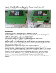
potentiometer accessible through a hole on the back of the unit (See Photo, page .1), should the factory
setting ever need changing. The display screens have a user adjustable presentation time (the time an
information or alert page stays on display, before moving on to the next one or back to the usual screen
for the mode the charger is in.) The presentation time (S_ViewTime*) is set slow enough (3-seconds
default) for most new users, who can speed it up later as they get used to seeing what is displayed.
With program Version 2.0, a key press is now seen during the ViewTime delay. Depending on the
position in the program or the message displayed, this key press may only immediately end the view
delay. In that case, another press will be required for the key to be interpreted and acted upon, when the
next LCD page is displayed and the user can see what the next key pressed will do. As with the previous
program version, typically a "beep" is sounded each time a key press is seen and another beep when the
ViewTime has finished. You can either wait for the ready beep or press a key to speed up the transition
to the next step. Watch the display to see whether your key press was acted on or whether it only ended
the ViewTime and you need to press it again.
The delay time is now entered as whole seconds, not milliSeconds (for example: “3” instead of
“3000”).
The following information applies to the Standby (Not Charging) state:
Initially, the top line of the LCD is active for scrolling the possible items for display. This means that
pressing the Left or Right Arrow key will change the item displayed on the top line, and the bottom line
is unaffected. The top line can display from a smaller list of the "favourite" items that are not editable,
for faster access to the one you want to see.. In other words, these items are values and times that the
charger has measured, rather than parameters that set limits, i.e parameters that can be changed to
8
modify charger behaviour.
Pressing the Down Arrow key will make the bottom line of the LCD active for scrolling and editing,
instead. There will be a brief indication of "Line 2 Active", to confirm that the charger has reacted
to the key press.
The bottom line is for editing parameters as well as viewing measured values and times. It can be
scrolled to display all the items available to the User or Factory/Technician, editable and not, according
to the current User or Tech level (Tech Extended Level Off or On).
Press the Up Arrow key to again make the top line of the LCD the one which is active for scrolling.
"Line
1 Active" will be displayed for the ViewTime on the top line.
Suggestion: Select items for display that are the most useful to see before charging. For example:
"Battery Volts" for the top line and the PTC value or a temperature for the bottom line. Scroll to check
that the battery temperature readings are suitable for charging.
Inlet Temp 87.0
OutletTemp 91.1
Inlet Temp 87.0
TempDiff 4.1
For one second in five, the LCD will flash a status message like the following:
Not Charging. R0
Profil 1 RunMd 1
or R 1 or R 2 ....R14, to indicate the reason it is not charging now.
The Reason codes are listed in the Stopping Charging section below. This provides an indication to the
user of what last happened to the charger to stop the charging (useful to know at a glance if you check
the charger and it has stopped). If the unit has not stopped a charging session since it was powered-up,
the reason will show as "R 0".
Typical Operation, Starting Charging (RunMode 1 or 2):
- Plug the car/battery harness to the charger.
- Plug the power cord to a 120V or 240VAC 50/60 Hz. outlet or extension cord in good condition. A
GFI 3 wire circuit is recommended for powering the charger.
- Turn on the power switch on the back of the unit
- Check that the battery Voltage and temperatures displayed are in the range expected for this battery
pack.
- If the charger operation or battery pack is to be different from the last use, edit the Run Mode and Car
Profile settings as required. (See instructions on how to do this below.)
- Press the START key and observe the displayed indications of Chargermode, Battery Voltage, Charge
Current, Charge Time so far in minutes and seconds, and milliAmp-Hours charge accumulated.
M6 159.2V 1056mA
9
CH 0:13 0mAH
Press the Down Arrow key to see another page of information: PTC value, Inlet Temperature (Ti),
Outlet Temperature (To), and the Difference between outlet and inlet Temperatures (Td).
PTC 82 Ti 64.1
To 68.3 Td 4.3
Press the Down Arrow key again to go back to the first display page and to toggle between pages.
Charger models and Specifications:
All chargers will operate on 90~264 VAC 47~63 HZ
GCIM1 (no longer available)
198V max @ 350MA Constant Current
1) 12V @1.2A (RS-15-12)
3) 48V @ .57A (RS-25-48)
1) 5-48V@ 350ma Constant Current (LPC-20-350)
GCM1 (no longer available)
250V max @ 350MA Constant Current
1) 12V @2.1A (RS-25-12)
4) 48V @ .57A (RS-25-48)
1) 5-48V@ 350ma Constant Current (LPC-20-350)
GCO1
250V max @ 350MA and 1050 ma Constant Current
1) 12V @3A (RS-35-12)
4) 48V @ 1.1A (RS-50-48)
1) 5-48V@ 350ma Constant Current (LPC-20-350)
1) 5-48V@ 700ma Constant Current (LPC-35-700)
How the Grid Charger Works:
It contains a 350mA Constant Current power supply (and a 700 mA CC power supply to make 1050 mA
total in "High Current" operation**) and 4 nominal 48V adjustable Constant Voltage power supplies
identified as P48A, P48B, P48C, and P48D. (P48D is not present in the GCIM1 charger.) P48A is
adjusted near its minimum at 41V. The other 3 are adjusted to near their maximum Voltage, around 54V.
These power supplies are switched in and out of operation so as to be able to provide any charging
Voltage from 7V up to about 245V. One or both of the Constant Current power supplies are always used
so that the charging is done in a Constant Current manner. For batteries/conditions requiring a Voltage
between 7 and about 42V, only the Constant Current power supply(s) are required as they can output
their full current over this range. For a Voltage range of about 42 to 69V, P48A will be switched on as
10
well by the microcontroller detecting the SwitchV1 threshold of 42V and operating a solid state relay to
add P48A's Voltage in series. The Constant Current power supply(s) will initially reduce their output
Voltage as required to maintain their set Constant Current output of 350 or 1050 mA. The CC power
supplies will gradually raise their output Voltage as the battery charges to maintain their target current.
When a little higher Voltage is required (over 69V, given by SwitchV2) the microcontroller will switch
off P48A and switch on P48B which can provide 54V instead of 41V. For the next Voltage range of 69V
to 96V, P48A will be switched back on and add its 41V to the equation. This continues if higher Voltage
is required (depending on CarProfile settings) up to the point that all of the 48V nominal Power
Supplies, P48A to P48D are on.
Stopping Charging:
There are many ways or Reasons for the charger to stop charging, in order to automate and optimize the
process of charging, and protect the battery. The reason the charger stops charging is displayed briefly
as it happens on the LCD, sent out on the serial port with the regular status reports, and kept and
displayed as the "R" indication on the "Not Charging" flash message. This message is shown one
second out of 5 seconds. (Reason indicated as R 1, or R 2, .... etc.) There are fourteen of these reason
codes at present, which advise the reason why the Grid Charger last stopped charging:
R1: Manual Stop, STOP key was pressed.
R2: The maximum allowed Voltage has been reached. (ChgStopVP1*, ChgStopVP2*, .......
ChgStopVP6*, depending on the CarProfile selected)
R3: The maximum allowed total charging time has occurred. (MaxChgTime*)
R4: The timed end of topping mode occurred. (TopTimeMN*)
R5: Battery now too hot to continue. (MaxPTCVal*)
R6: The TEST button was pressed.
R7: The maximum allowed milliAmp-Hours charge was supplied to the battery (MaxChg_mAH*)
R8: End of Topping charge due to Voltage plateau detected.
R9: Temperature Differential (Outlet - Inlet Temperature) target reached, meaning the charging energy
received by the battery is now going into heat rather than raising the state of charge.
R10: Higher current than expected through power supplies
R11: Too HOT Outlet Temperature
R12: Too COLD Inlet Temperature
R13: Too HOT Inlet Temperature
R14: Too Cold Outlet Temperature
Pausing Charging:
Press [PAUSE] to suspend charging. (This works while actively charging, not while in a Delay Wait
(Run Modes 3 or 4) or Delay Interval (Run Mode 5) period or discharging (Run Mode 6).) The LCD
indicates:
PAUSE Charging.
Keeps Chg. data.
This Pause Mode will allow a parameter to be changed without losing track of information on the
charging process up to that time, such as the charge time and milliAmp-hours delivered to the battery.
The LCD will flash the status message on the top line:
Pause Charge R 0
11
every 5 seconds so long as the charger remains paused. Press [START] to resume charging. The
charger may back down by a "chargermode" (for example from M6 to M5) if the battery Voltage has
decayed below a boundary switch-point while charging was paused.
Car Profiles ( Matching Battery Pack Charging Requirements):
Six programmable Car Profiles are available for selection in Setup. These allow the charger to be
quickly switched between 6 different car models or battery pack types. They can also be used set to the
same battery/car type for people with 2 or 3 Insights or Civics (but with a different year edited for each
description), for the best match between each car harness and the charger. (In other words, associate
each car and its harness and temperature sensors, with a different CarProfile, even though the cars are
the same model.) Which CarProfile the charger is now using is selected in Setup. How each CarProfile
will control the charging and the description displayed for it, are determined by editing 3 parameters for
each CarProfile, explained below.
Following are examples of typical CarProfile descriptions, seen when the charger is turned on and in
Setup:
InsightGen1 2000
144V Profile = 1
Civic HCH2 2006
158V Profile = 2
ToyotaPrius 2006
202V Profile = 3
CarProfiles have their descriptions automatically generated, from the "Model_Yrn* " parameters
(where n is 1, 2, 3, ..... or 6 to match the CarProfile number) and from the corresponding programmed
Cut-back Voltages. This gives the user an approximate indication of the nominal battery pack Voltage
each CarProfile can be used to charge. CarProfile 4 is usually factory set for for a 158V pack, for Honda
Civic 2nd generation and Accord cars, while CarProfile 5 is usually factory set for Toyota Prius 2004+
and CarProfile 6 is usually factory set for Honda Insight II.
The following parameters are programmable for each CarProfile, using EDIT:
Cut-Back Voltage:
This is the Voltage level at which the charger switches to low-current topping charging - User Editable
Cut-backVP1*, Cut-backVP2*, Cut-backVP3* .......... Cut-backVP6*
Cut-backVP1* 166
Note: In addition to creating the nominal pack Voltage value for display (calculated as = 0.862 X CutbackVPn) as mentioned above, the Cut-backVPn is also used to determine the Low Voltage Start Point
in Long-Term Maintenance charging. (calculated as = 0.88 X Cut-backVPn)
Maximum Voltage:
This is the highest Battery Voltage allowed and when reached, charging will be stopped - User Editable
ChgStopVP1*, ChgStopVP2*, ChgStopVP3* ............... ChgStopVP6*
ChgStopVP1* 180
12
Car model and year:
This parameter is interpreted to display the Car model and year, as explained below- User Editable
Model_Yr1, Model_Yr2, Model_Yr3
Model_Yr1* 100
Model_Yr4* 306
This will display as "InsightGen1 2001"
and this as Civic HCH2 2006
and ToyotaPrius 2006 for CarProfile5 in this example:
Model_Yr5* 506
Here are the choices and what number to enter (by editing) for each Model_Yrn parameter:
Car Model Coding: (where the 2-digit year is entered in place of "xx")
0xx = " Custom Car " This allows for a car or Battery Pack not on the list of models.
1xx = "InsightGen1 " Typical/Default Cut-backVPx* = 166, ChgStopVPx* = 180
2xx = " Civic HCH1 " Typical/Default Cut-backVPx* = 166, ChgStopVPx* = 180
3xx = " Civic HCH2 " Typical/Default Cut-backVPx* = 183, ChgStopVPx* = 200
4xx = "
Accord " Typical/Default Cut-backVPx* = 166, ChgStopVPx* = 180
5xx = "ToyotaPrius " Typical/Default Cut-backVPx* = 233, ChgStopVPx* = 245
6xx = "InsightGen2 " Typical/Default Cut-backVPx* = 116, ChgStopVPx* = 126
In addition, sets of temperature offsets are associated with CarProfiles 2, 3, 4, 5, and 6, so the the Grid
Charger can be calibrated at the factory to best match the temperature sensors of each different car
harness:
Calibration offset for the Inlet temperature sensor on each car/harness - Factory/Tech Editable
InTemp2Cal*, InTemp3Cal*,InTemp4Cal*, InTemp5Cal*, InTemp6Cal*
Calibration offset for the Outlet temperature sensor on each car/harness - Factory/Tech Editable
OutTemp2Cal*, OutTemp3Cal*,OutTemp4Cal*, OutTemp5Cal*, OutTemp6Cal*
Run Modes:
The Run Mode is selectable by the User to match the need for charging immediately, only after a delay,
or for continuously scheduled charging with long intervals between topping up. These choices provide
flexible operation to suit varying circumstances, like returning home with a hot pack and charging later
when it has had some time to cool down. In addition, there are two run Modes for discharging the
battery pack. The Run Modes available are:
Run Modes 1** and 2:
Manual Charge with No Delay, High** and Low current, respectively. Works one time once START
has been pressed. Only use Run Mode 2 for the Low Current Maintenance Charger. (If you edit the
Run Mode to 1 by mistake with a Current Maintenance Charger, it will be corrected to 2 right after by
the charger.) Starts charging immediately and stops automatically or by pressing the [STOP]. The
13
operation and LCD information are as described in the earlier section on Typical Operation, Starting
Charging.
Run Modes 3** and 4:
Delayed Start of Charge, High** and Low current, respectively. Works one time once START has
been pressed. Only use Run Mode 4 for the Low Current Maintenance charger. (If you edit the Run
Mode to 3 by mistake with a Current Maintenance Charger, it will be corrected to 4 right after by the
charger.) Starts charging after the programmable Start Delay (minutes to hours) has expired and stops
automatically or by pressing [STOP]. The Start Delay is programmable in Minutes, from 1 to 9999
(166+ hours) , by editing the "StartDelay*" parameter.
Not Charging R 0
StartDelay* 60
After pressing START with Run Mode 3 or 4 selected, the display shows the Run Mode description on
the top line: Start Delay Hi C or Start Delay Lo C
and then the display shows:
Charging starts
in 60 minutes The actual delay time will be shown.
Once started and waiting for the delay to count down, the display will indicate every 5-seconds on the
top line, the time remaining, in minutes, before charging will be started.
Start 2 min.
Profil 1 RunMd 4
Run Mode 5, Long Term (Storage) Maintenance Charging, Low current:
In this mode, the charger cycles continuously between a waiting, off, interval and a charging time, to
keep the battery pack charged. It works this way once START has been pressed, until STOP is pressed.
It starts up in the Wait Interval, not charging, and indicates the time remaining before starting to charge,
on the LCD.
Charging begins after the Wait Interval (IntervalHrs*) counts down to zero, or if low battery Voltage is
detected. ("Low Voltage" is calculated based on 88% of the edited Cut-backVPn, about 147V for a First
Gen Insight or Civic and 161V for a Second Gen Civic or an Accord.) The Grid Charger then charges
for a programmable Maintenance Charging Time (MaintRunTme*) or until charging is suspended
automatically due to a full or hot battery. The charger then returns to the Wait Interval to start over. It
will continue cycling off and on indefinitely until [STOP] is pressed.
The Wait interval is programmable in hours, from 1 to 9999 (416 days) , by editing the "IntervalHrs*"
parameter. This is the interval between the end of the previous charge and the start of the next.) The
maximum Maintenance mode charging time is programmable in minutes, from 1 to 9999 (166+ hours),
by editing the "MaintRunTme*" parameter. It is usually set to a shorter time than the other single
operation Run Modes.
14
Not Charging R 1
IntervalHrs* 168
Not Charging R 1
MaintRunTme* 360
StopAlarm reminder beeps are not activated for Long-term Maintenance RunMode 5, as the user is
likely not nearby to hear them, while the continuing beeping could annoy other people.
After pressing START with RunMode 5 selected, the display shows the RunMode description on the top
line: Storage Maintain
and then the display shows:
Starting long
Term Maintain.
Then the LCD will indicate the time remaining in hours and minutes on the top line of the Alternate
Display every 5 seconds:
Start in 168H00
Profil 1 RunMd 4
Once the IntervalHrs* waiting, off time between charges has expired, charging will start and the LCD
will indicate:
WaitTime expired
Starting charge.
If the charging is started because of low Voltage, before the Maintenance wait time interval expired, the
LCD will indicate:
Voltage too low,
Starting charge.
(Usually, no-one is present and looking at the LCD when these starting messages pop up!) After the
"WaitTime Expired" or "Voltage too low", reason for starting charge message, the usual charging display
will be shown, with the option available to press the down arrow for the alternate charge display.
Run Mode 6, Discharge/Charge Cycling:
Mode 6 is intended for use in discharging a battery pack to optimize the battery capacity and
performance. It is also a good diagnostic aid in determining the battery condition and in finding specific
sticks/modules that require refurbishing, i.e. cell replacement.
The charger is designed to be used in Mode 6 (and mode 7 described later) with an accessory discharge
load, so that the pack is being discharged during the period between charges. When started in Mode 6,
the Auxiliary Output (available from a connector behind a hole plug on the side of the charger case, once
installed) is turned on to enable the solid state relay to connect the discharge load.
The "Serial Always" option is automatically set for this mode so that key data will also be sent out the
15
serial port during the discharge half of the cycle. This will enable monitoring and graphing the
discharge curve, when connected to a data logger computer/program. The Option bit for 1-minute/ 5seconds serial reporting should be set on, to 5-seconds, for the best detail when monitoring the discharge
using the Labview program.
A separate discharge time variable "DisChgT "is used by the program to count up and indicate the
minutes of time spent discharging. From 1 to 3 discharge/charge cycles can be selected by editing the
User parameter C_DcyclesMax*. At the end of this programmed number of discharge/charge cycles,
the Grid Charger will stop once it has completed the final re-charge. The data from all of the cycles was
stored in non-volatile memory (Bank 0 or Bank1, depending on the Options choice) and is available to
view on the top line of the LCD. An Option in SetUp is provided to choose between doing a pre-charge
before starting the first cycle, or skipping the pre-charge and going straight into the start of discharge.
After pressing START with RunMode 6 selected, the display shows the RunMode description on the top
line:
Discharge Cycles
Starting Dischrg
/Charge Cycling.
and then the display shows:
Then the LCD will indicate information like:
Batt Volts 155.3
Discharge 0:05
indicating the time counting up in minutes and seconds on the bottom line.
Besides C_DcyclesMax*, there are two other User editable variables that affect Discharge:
"MinDischrgV*" and SlopeDifMax*.
"MinDischrgV*" is provided to set the minimum allowed Voltage threshold at which discharge will be
stopped (if not stopped sooner by one of the other methods). The factory default value is 130V, intended
for the Honda Insight 1. There is only one "MinDischrgV*" (not one per Car Profile, as with the Cutback and ChgStopV). While there are several other detection methods that will almost always stop the
discharge before reaching this safety limit minimum Voltage, it is strongly recommended that this value
be changed for discharging a battery pack other than the 144V nominal default. Suggested values are:
143V for a 158V pack, 182V for a Prius 201V pack
A second, higher, threshold or switch-point is calculated from the Cutback Voltage of the chosen Car
Profile. The formula is 0.9 X Cut-backVPx, which is about 153V for 144V Insight packs. This
determines a "lower limit for starting testing" by the two methods for detecting a good point in the
discharge curve to stop. This "lower limit for starting testing" backs up the usual start point determined
by finding a minimum in the difference between the Long-term and short-term Voltage Averages (the
flattest portion of the discharge curve) Which ever start point (Voltage value) is higher (reached first) is
stored as "SmpStartV ", displayed in the discharge serial output and used to start the sampling/testing for
determining the end of discharge. More about this later....
The grid charger will begin the 5-seconds Voltage sampling when the battery Voltage has dropped to
this "SmpStartV " value. In other words, as the battery is getting more discharged, this SmpStartV"
Voltage is reached and the Grid Charger will watch it more closely, and check whether the rate of
discharge indicates the discharge should be stopped. At the instant of each 5-seconds sample, there is a
beep (unless disabled by the ALARM key) and the indication "Smpl" at the top left of the LCD, so the
user can be aware of the progress and faster sampling. At the end of the first 5-bits drop from the start
16
of rapid sampling (about 1.2 Volts further drop), a determination of the rate or slope of discharge is
stored. This reference value is used to later stop the discharge (before the minimum "TestDischgV*") if
a relatively too fast rate of Voltage drop indicates a weak cell reversal may be about to occur.
In addition, there is a further "sanity" check : if the Voltage is seen to be dropping abnormally fast (in the
slope determining region around the D_SmpStartV* Voltage), the discharge will be quickly stopped.
(Usually this indicates a battery in very poor health that will need to have some cells replaced before a
satisfactory capacity can be achieved).
Once the pack discharge has been stopped by any of the 4 methods, (fast dropping Voltage, the discharge
slope has started accelerating down to the calculated cut-off rate, the minimum Voltage has been
reached), or the Averages Difference method has its rapid change threshold met, or the time-out (not
likely), then discharging ends. The discharge load is disconnected (Aux Output switched off). If
enabled, the stop alarm beeps will alert the user to the end of the discharge period. The reason for (i.e.
the method for deciding) the end of discharge is stored and indicated as "DisR". At this time, the
charger will start the charge part of the Discharge/Charge cycle. The recharge will start at the high (1
Amp.) rate if the charger is the Overnight type.
Temperature out of limits (either the Inlet or Outlet temperature sensor reads too high or too low) during
RunMode 6 charging will cancel operation, turning the charger off.
After the battery has been recharged, the grid charger will check whether the maximum number of
cycles has been done up to now and if so: stop operation and change to standby "Not Charging"
condition, requiring user action before doing anything else;
or, if one or 2 cycles remain to be done: automatically start the next discharge cycle.
This number of Discharge/Charge cycles is entered by editing the C_DcyclesMax* User parameter to a
value of 1, 2 or 3 cycles. The data for each of the Discharge/Charge cycles is displayed on 3 pages in a
special LCD top line scrolling region, next (to the left of) the Battery Voltage position. This set of data
is stored for later recall and viewing in one of 2 memory banks, selected in SetUp/Options, as either
Bank 0 or Bank 1. This means that a previous or first set of data can be saved in one memory bank
while recording the latest data in the other bank. (This Options choice , of to which active Bank to next
save data, is remembered after the unit has been powered off, so there is less chance of over-writing the
set of data you want to keep.) In addition, this data is available to be read out the Serial Port from the
EEPROM storage Data Bank.
Stop Discharging list of reasons:
DischR = 1: Manual Stop, STOP key was pressed.
DischR = 2: End of discharge slope drop-off detected. (Battery Voltage graph dropping rapidly signals a
cell drop-out or overall pack nearing end of safe Discharge)
DischR = 3: Low Voltage, reached the MinDischrgV* level
DischR = 4: Discharging too fast, Voltage dropped too quickly through the slope sampling region at
D_SmpStartV*. (This could indicate a low capacity or otherwise damaged pack.)
DischR = 5: Time-out, discharging reached the IntervalHrs* Time. (This is not likely to ever occur
unless IntervalHrs* is changed to a low value like 2 hours.)
DischR = 6: End of discharge determined by the difference between the Long-term and Short-term
Voltage Averages exceeding the SlopeDifMax* set value. (Battery Voltage graph dropping rapidly
signals a cell drop-out or overall pack nearing end of safe Discharge)
17
Discharge/Charge Cycles Display:
There are six special 4-page display items: (2 Banks of 3 Cycles per Bank), for viewing of the
Discharge/charge Cycles information. These are accessed on the LCD Top Line to the left of the Batt
Volts item. Scrolling with the left and right arrows over this area selects the first "Title Page" of each.
Bank0 Cycle1, P1 Bank0 Cycle2, P1 Bank0 Cycle3, P1 Bank1 Cycle1, P1 Bank1 Cycle2, P1 Bank1 Cycle3, P1
Select Pg: v & ^ Select Pg: v & ^ Select Pg: v & ^ Select Pg: v & ^ Select Pg: v & ^ Select Pg: v & ^
When the display is on one of these 6 Bank and Cycle display items, pressing the Up or Down arrow
will select another page of data to view. There are 3 data pages with 4 data items on each, plus the "Title
Page", for a total of 4 pages for each of the 6 Bank and Cycle display items. Pressing the Down or Up
Arrow navigates from page to page and wraps around at each end of the list of pages
Bank1 Cycle3, P1 Indicates which cycle and Bank are being displayed.
Select Pg: v & ^ Reminds about the Down and Up Arrows used to select pages.
DCT 125 SDV160.4 Discharge Time, Start Discharge Voltage
DisR 2, EDV139.6 Discharge Stop Reason, End Discharge Voltage
PAH 35 SCV139.3
ChSR 8, ECV171.2
Percent Amp-Hours capacity charged, Start Charge Voltage
Charge Stop Reason, End Charge Voltage
mAH 2275 WtH 342 milli-Amp-Hours charged, Watt-Hours charged
ChT 360, TpT 35 Charge Time, Topping Time
Disabling Automatic Stop of Discharge mode: "Slope Stop Disable"
This is a special testing mode that requires the Password and Tech Edit selected in SetUp, before it
will work.
The two principle methods used to detect the end point for stopping discharge can be disabled if the
discharge operator is watching the discharge (using the Labview program) and wants to take it further,
with manual intervention. This feature is recommended only for experienced operators, after the battery
pack has been characterized using the normal automatic discharge. The automatic safety stop methods:
"Minimum Voltage reached" and "Falling too rapidly through the test Voltage Zone" are not disabled and
remain in effect. These would not be triggered for almost all normal ranges of battery pack conditions,
but would stop discharge if the operator failed to do so, before conditions became too extreme.
To activate Slope Stop Disable, Press TEST when discharging. The display will show:
18
SlopeStopDisable
now turned ON.
The Discharge time message on the second line will now change from Discharge
23:13
to
DischTEST 23:13
Then, later if the Slope method determines that the condition has been satisfied that normally would
automatically stop the discharge, the Discharge time message on the second line will now change to:
DischT*** 23:13
and a long beep will sound at every 6-seconds sample interval.
If the Voltage Averages Difference method determines that the condition has been satisfied that normally
would automatically stop the discharge, the Discharge time message on the second line will change to:
DischTAVG 23:13
and a long beep will sound at every 6-seconds sample interval.
Press TEST again while discharging to turn off this Slope Stop Disable feature. Then it will no longer
inhibit automatic detection of when to stop discharge. The display will show:
SlopeStopDisable
now turned OFF.
Variables and defined factors that affect this mode:
User Variables/Parameters that affect the operation of this mode: C_DcyclesMax*, SlopeDifMax*,
MinDischrgV*, Cut-backVP1/2/3/...6* depending on the Car Profile selected, A-HrCapac*, IntervalHrs*
Derived variables using the above user variables and pre-defined multiplier factors:
D_SmpStartV = 0.90 (#define FactorD_SmpStartV) multiplied by the CutbackV. If the sampling start
point was not already found by the minimum of Voltage Averages difference method, then sampling for
determining the end of discharge, will start anyway at this Voltage.
Defined constants (pre-determined, fixed):
#define AvgDifMinCnt 48 The number of 5-second samples that DifAvgVminRaw must not change to
have found the minimum value for the difference of the Long-term & Short-Term Averages
#define MaxDifForMin 40 If VbitsSmpDifX10 is still higher than this when minimum AvgDif is
found, don't accept it as the minimum to start Averages difference and Slope/point methods for
Discharge Stop. This will eliminate the false early minimum found with some Prius 2004+ packs under
certain charge states and pack condition.
#define InitFastDischT 101 //Less than this short time counting 5-bits V drop slope samples will
trigger the end of discharge for reason 4.
Protected (Tech Edit) Variables/Parameters that affect the operation of this mode: DischSmpFac*
Options to select before starting:
1-minute or 5-seconds serial reporting,
Do pre-charge first or start in discharge
19
Run Mode 7, Pulsed Discharge, no charge current:
User Variables/Parameters that affect the operation of this mode: None.
Protected (Tech Edit) Variables/Parameters that affect the operation of this mode: None.
This is a special testing mode that requires the Password and Tech Edit selected in SetUp, before it will
work. There is a warning long beep and LCD message if there is an attempt to start operation in this
Run Mode without being in Tech Extended Edit user level:
Can't PulseDisch
Needs TECH Level
When started in this RunMode, the Grid Charger pulses the discharge load (Aux. Output) on and off at a
very fast rate of about 22 Hz. (22 on and off cycles per second). It is intended for use with an AC
Voltmeter to provide an idea of relative internal resistance of the battery pack (not for doing a discharge
cycle of a charged battery pack). This mode provides a means to indicate how the internal resistance
compares with a good or bad battery pack, whether it is improving as the pack is charge/discharge
cycled, and which sub-packs are likely sub-par.
There is a time limit on operation, to avoid overheating the solid state relay in the discharge load: 90
seconds for battery packs below 170V and 45 seconds above 170V (Toyota Prius).
After pressing START with RunMode 7 selected, the display shows the RunMode description on the top
line: Pulsed Discharge
Starting Dischrg
Pulsed Aux. load
and then the display shows:
Press STOP when your test is complete, to end this Pulsed Discharge operation.
Using the EDIT Function:
First, make the Bottom display line on the LCD active by pressing the Down Arrow key if the charger is
not operating. If charging, press EDIT to change the bottom line from the charging display to the single
parameter display. (Be careful what you Edit/change while charging!)
Scroll to select the item to edit, using the Left and Right Arrow keys.
Note: More items are available to edit in Tech Access than in User Access. These additional parameters
are mostly calibrations that should not be changed by the user. Altering these, except as directed by
Genesis One, can cause the charger to overcharge, undercharge or otherwise malfunction and risk
damage to the battery pack.
Press EDIT to make the value field editable.
Using the Left and Right Arrow keys, move the cursor to the digit position to be changed.
Press the Up and Down Arrow keys to Increment (increase) and decrement (decrease) the value of the
digit to arrive at the desired number.
For most parameters, there is a safeguard limit of 9999 as the maximum value that will be retained.
20
(Exceptions are the calibration Tech Edit parameters) This is done so that the user will not inadvertently
enter a higher number by incrementing the thousands digit past nine to raise the not-displayed 10thousands digit above zero. When another press of the UP arrow would have raised the parameter past
9999, it will be held at this maximum. When another press of the DOWN arrow would have wrapped
around the parameter value past 0000 to 65535 (the maximum value of a 16-bit number) it will be
constrained to 0000.
Move the cursor to another digit to be changed, if required, (using the Left and Right Arrow keys) and
then change its value (again, using the Up and Down Arrow keys).
When the correct value for the parameter is displayed, press the EDIT key a second time to save the new
value and exit Edit, returning to Display mode. If you want instead to abandon the changes made and
not save them, then press STOP instead of pressing EDIT the second time.
For the Tech calibration parameters with negative values allowed, such as CurrentCal, a down arrow
press below 0000 will show "5535". Press EDIT to end and save the change and it will be displayed as
"-1". Pressing edit again to go back and re-edit this value will display "0255" now for editing. Press the
down arrow a number of times and the 0255 value will decrement by that number. Press EDIT to
complete the session and the value will be displayed as a negative number.
Be careful about changing parameters if you are not sure about what you intend to accomplish, the effect
of changing a each parameter and the correct value to use for your battery pack and environment. For
example, reducing the SampleTime* too much, from its default 30 minutes to below about 10 minutes
for an Overnight charger, could result in a false detection of the Voltage Plateau (Voltage no longer
increasing) and a premature end of charging.
Changing the Run Mode:
Press the RUN MODE key. The RunMode* variable will automatically be selected for display and
editing on the second line of the LCD: RunMode* 1
Press the EDIT key to place a cursor in the RunMode value field for editing.
RunMode* 0001
Follow the EDIT instructions above to change the value/choice of RunMode, and save it.
RunMode* 0003
If an invalid RunMode, such as 8 or 0, is entered, the warning "Invalid RunMode" will be displayed.
The Run Mode will be forced to 1 to prevent an invalid Run Mode being saved. When EDIT is pressed
to end and save the change, the value will be checked for suitability with the charger model. If a "1" or
"3" was chosen for a 350 mA charger model (the charger is not an Overnight 1.05 Amp. model), the a
"1" will be changed to "2" and a "3" changed to "4" and the corrected values over-written.
Using the SETUP Function:
Pressing the SETUP key places the charger in Setup Mode, starting with the first item: Car Profile.
The display briefly shows the information describing the Car Profile, including car model and model
year, for example:
InsightGen1 2000
21
144V Profile = 1
Then the LCD will prompt:
[EDIT] to change
CarProfile* 1
Each press of [SETUP] will move to display the next Set Up item and at the bottom of the list will
return to the first item.
SetUp Navigation Diagram:
CarProfile.
Options
Restore User Defaults
Car Profile:
Car Profile is a 6-choice item, with the current choice shown on the bottom line of the LCD.
When the LCD prompts:
[EDIT] to change
CarProfile* 1
Press EDIT and the LCD shows, for example:
InsightGen1 2000
CarProfile* 0001
Use the Up or Down Arrow Keys to select the desired Car Profile from 1 to 6. As soon as the Car
Profile number has been selected, the corresponding description will be shown. Once EDIT has been
pressed the second time, the Car Profile will again be displayed, including the calculated nominal
battery pack Voltage, for example:
ToyotaPrius 2005
202V Profile = 5
Always press STOP when finished with Setup (Except for the Tech Extended level option, which has an
automatic exit once completed). If you want to cancel editing (before the second press of EDIT), press
STOP. Then, to exit Setup, press STOP again.
22
If you want to change a SetUp item other than CarProfile, press SETUP again to point next to "Options".
Options:
The Options which the user can change are:
Soak Time On/Off; Store Discharge Cycles Data in Memory Bank 0/1; Cold Charge, Yes/No;
Serial output only when charging or Always; User/Tech edit; Change Temperature Degrees F/C;
1-minute or 5-seconds Serial reporting interval; Charge before Discharge, Yes/No?
Only 2 of these options are remembered after a power-off: Memory Bank 0/1 & Temperature Deg F/C
When the "Options" function has been selected in SetUp, the LCD will display:
Options Display:
Chg: press Down.
The LCD 2nd line message reminds the user to press the Down Arrow Key to toggle the Option Bit
between the "0" and "1" choices.
After the ViewDelay, the Options Display page is then shown on the LCD. The current state of all 8
Options choices (8 Options Bits) is displayed as a series of "0" or "1" indications on the bottom line of
the LCD. Initially, the cursor will be on the first one to the left, and the LCD top line will show the
description and current state of the first option. The default state is all options at the "0" choice.
Xtra Tm Soak Off The extra time for soak charging is turned off
Options 00000000
Press the Down Arrow if you want to toggle the choice. (The up arrow is not active for this function
and will prompt a reminder to use the Down arrow.) As the bit is toggled between "0" and "1", the top
line of the LCD will update to display the current choice.
Xtra Tme Soak On
Options 10000000
Use the Left and Right Arrow keys to scroll through the 8 Options on the bottom line, to select the one
to view and change. As each one is selected, the corresponding description and state of the Option will
be shown on the LCD top line. When you get to the end, the cursor will wrap around and go from the
last to the first item or from the first to the last.
Brief Description and Displays for Each Option:
Soak Period After "Voltage Plateau Detected" End of Charge, Off/On:
Provides extra charging time in the Topping Phase, up to the value of the TopTimeMN* parameter. The
default value is 540 minutes. Detection of the usual "Voltage Topping Plateau" ending will be ignored
and charging will be continued until either the maximum Topping Time or the Maximum Total Charging
23
time have been achieved. See the section above for the LCD screens.
See the explanation of "Soak" in the section: "Further Explanation of Charger Operation...."
Bank 0/1:
Selects in which of the 2 Memory Banks to store the data such as Start Voltage, Stop Voltage, Stop
Reason, etc., for the next Discharge/Charge cycle(s), when using the Grid Charger in Run Mode 6.
Bank 0 Selected.
Options 00000000
Bank 1 Selected.
Options 01000000
Allow Charging at 10 degrees F colder than Normal Limits:
For the choice of allowing charging at temperatures 10 degrees F (about 5.5 degrees C) colder than the
standard low temperature limits, the LCD prompts:
Cold Charge > No
Options 00000000
Cold Charge >Yes
Options 00100000
Use this option only if you really need to charge now and cannot warm up the car & battery
pack sufficiently to work with the standard low temperature limits. This selection is not
remembered after the unit is powered Off . It reverts to the standard low temperature limits the
next time the charger is powered up/ turned On.
Serial Output Only During Charging or Always:
For the choice of when to send serial reports (at the 1-minute or 5-seconds interval selected by the last
option):
0) Only when charging or while operating in Run Mode 6 (Discharge Cycles); or
1) All the time the charger is powered On,.
Serial >Chg Only
Options 00000000
Serial > Always.
Options 00010000
Pressing the Down Arrow key at the above screen will toggle the "Serial Always" operation on/off and
show the current setting on the top line.
This selection is not remembered after the unit is powered Off and then reverts to the standard behaviour
of sending serial output only when charging.
Parameters Viewing & Changing Access Level:
For the choice of Access Level, Regular User Level or Technician Level, the LCD prompts:
24
Tech Edit Off.
Options 00000000
Tech Extend Edit
Options 00001000
If the correct password has been entered, Technician Level Extended Editing Capability can be selected.
Only select Tech Access when the charger is disconnected from the car battery (or any battery) .
Without the valid password, the Access Level can only be User Level (Tech Extended Edit Off).
The "Tech Extend Edit" message indicates that Technician level access has been set, after the Down
arrow key was pressed. Press it again to return to the previous choice.
Password Not Entered or Incorrect:
Note: The password is reset to "0" each time the charger is powered off and will need to be re-entered, if
access to the Tech parameters is required. For all other charger operation and use, except TEST and
Pulsed Discharge, (Run Mode 7), the password is not needed. If the correct password has not been
edited in to the Password parameter, this will be indicated on the LCD bottom line after the Down Arrow
is pressed in Setup, Tech Edit:
Invalid Password
Wait for the Password variable to next be displayed on the bottom line.
Password
0
The Grid Charger will automatically set up EDIT, ready to enter the correct Password using the arrow
keys. Once the password has been entered correctly, press EDIT, to save it.
If the password was entered correctly, the charger will automatically select the Tech Edit choice
and Stop (Exit) SetUp. The display confirms this by showing:
Tech Extend Edit
Exiting Setup.
Change Temperature Degrees (F or C):
For changing the degrees C or F used for display, the LCD prompts:
Temp > degrees F
Options 00000000
Temp > degrees C
Options 00000100
Pressing the Down Arrow key at the above screen will change the degrees C or F used for display and
show the current setting on the top line. This selection is remembered after the unit is powered Off .
1-minute or 5-seconds Serial reporting interval:
1min Serial data
5sec Serial data
25
Options 00000000
Options 00000010
Change to the 5-seconds interval for serial data output only if fine detail and lots of data is desired and
can be accomodated by the receiving data logger program. This selection is not remembered after the
unit is powered Off .
Charge before Discharge, Yes/No?
Charge B4 Dischg
Options 00000000
No Precharge.
Options 00000001
If the charger should automatically recharge the pack before starting the first discharge/charge cycle,
leave this option at "0". For no pre-charge, press the arrow key down to select "Yes" instead of the
default "No". This selection is not remembered after the unit is powered Off .
Reload Defaults:
The third and last SetUp function is Reload Defaults, accessed by pressing the SETUP key when at
Options.
Reload Defaults
press [<] now.
To restore the User parameters to the factory defaults, press the left arrow key. The User parameters are
the items with an "*" at the end of the name that are editable on the bottom line of the display in User
Mode. (This function will not over-write the Tech parameters section of memory, to avoid losing the
factory calibrations.) A brief message will indicate that the restore has been prepared:
Restore Defaults
has been setup.
Then the next LCD page will be displayed, giving the instruction to switch the AC power off & on:
Switch power off
& on to activate
If a key other than [<] was pressed, the charger will not proceed with restoring the factory defaults and
will indicate on the LCD that this action has been cancelled due to the wrong key pressed.
Restore-Defaults
26
cancelled Wr Key
(cancelled, Wrong Key)
If you pressed STOP to cancel and see the above message, and now want to end SetUp, then press STOP
again to exit.
Press STOP to end SetUp:
At this point, either press STOP to end SetUp or press SETUP again to rotate around to Car Profile.
Always press STOP when finished with Setup, (except not required for Options/Tech Edit) so the
charger will end Setup function and not make an unexpected change the next time that the Down Arrow
key is pressed.
TEST:
This function is normally only used at the factory, to test and adjust the power supplies. It can also be
used to check that each power supply is working and is still close to its original factory Voltage
adjustment. Test Function works only in Tech Access level (Tech Extended Editing), not in User Access
level. If TEST is pressed when not in Tech Extended level, the LCD will warn:
Can't do TEST Md (Can't do TEST Mode)
Needs TECH Level
Only select TEST when the charger is disconnected from the car battery (or any battery) . Note:
The Test Mode will not start if the charger sees battery Voltage. In that case, the charger will warn
on the LCD:
Can't do TEST Md (Can't do TEST Mode)
Battery detected
Insulate any battery wire connection leads or plug so no short circuit can occur.
Press TEST to select Test Function and point to the first/next Test step in the sequence. The first step
switches all the power supplies on. Briefly, after TEST has been pressed, the LCD shows "Test Mode
Now 1" on the top line and a message like "Saved PS V 198.8" on the bottom. The display then looks
like:
Batt Volts 198.5
1 198.8VS 0mA
The Batt Volts 198.5 shows what is being measured now in this step . The bottom line indicates "1" for
step 1, 198.8VS for the Voltage measured and saved to non-volatile memory during a previous test or the
factory calibration, and 0mA as the current now (When done as a factory test with a resistor load
drawing current, the actual current will be shown instead of 0.) Press EDIT (once only) to replace the
previously stored test value with the present value. Be sure that you want to over-write the original
stored value and also to wait for the Voltage reading to stabilize before pressing [EDIT] to take the
Voltage sample. Unless a power supply output has been re-adjusted, or a power supply replaced, stay
with the initial sample to keep as a reference for comparison.
Press the Down Arrow key in this step 1, to turn off the PCCHI power supply**, to test at 350 mA, if a
27
test load is being used. Press the Up Arrow key in this step 1, to turn the PCCHI power supply** back
on. (** indicates "Overnight charger model only")
Each subsequent press of TEST will move to the next Test step, selecting only one of the power
supplies to be on for testing and adjustment. There are 7 steps in total. If PAUSE is pressed during Test,
the power supply(s) will be turned off and the position in the sequence remembered. Press START to
resume testing at the same step as before, when PAUSE was pressed. Press STOP to end Testing and
reset the step counter to step 1, for the next time this function is used. Or, if TEST is pressed enough
times to cycle though all the steps, the following screen will be displayed:
End of TEST Mode
TEST to restart.
Press TEST only if you need to get back into the Test mode. Otherwise, just wait a couple of seconds
for the display to indicate that the charger has returned to the Off, not charging, condition.
Serial Output:
Setup Parameters and hardware:
The configuration required for the receiving computer or data-logger is:
9600 Baud, 8 bits, No Parity, 1 Stop bit (9600 8-N-1) The RS-232 interface is isolated from the highVoltage connections and the vehicle Voltages by opto-couplers.
Input as well as output on the Serial Port:
From program version 2.0, the Grid Charger is able to receive commands from a serial connected PC or
lap top. These are described in the "Serial Input" section a few pages below.
What is sent out from the Serial Port:
The Grid charger outputs data:
1) Regularly at set intervals according to charger operation and its Option settings
2) On demand, in response to commands received on the serial port.
The Grid charger outputs data providing the status and values of key variables every minute during
charging and discharging, and at significant changes in operation, like an automatic stop. The RS-232
interface is provided on a DB9 Female connector that can be hooked to a computer serial port or USB to
Serial adapter, using a standard DB9 Male to DB9 Female, straight through, serial cable. A terminal
program in the computer, such as Hyper-Term, can be used to receive and display the data. Alternately,
the serial port can be coupled to a data logging device for later viewing and analysis. A custom program
is available from Genesis One to do data logging, graphing and control of charger operation, plus
reading and editing of the parameters from a PC instead of using the unit's keypad and LCD.
28
Power-on Serial Output:
At program start-up, the Grid Charger outputs a message like:
"Prod Gridcharger, V2.0 Code 03/22" This is the ID and Program Version message.
“Start Charging” Serial Output:
A new “Start Charging” Headings line and then a line of corresponding data is sent:
- When START is pressed
- When charging is about to start at the end of the delay-start of charging in Delayed Charge
(RunModes 3 & 4)
- When charging is about to start at the end of the Wait Interval in Long Term Maintenance Charging
(RunMode 5)
- At low Voltage start in Long Term Maintenance Charging (RunMode 5)
- When charging is about to start at each Charge of a Discharge/charge cycle (Run Mode 6)
This “Start Charging” Headings line is:
SSET, Profile, RunMd, CutBakV, VMax, TopTime, Max CGTm, MaxAH, SampleTm, TDMax, Soak,
ColdChrg, VSmpDif, CDcycles, DcSmplF, MinDcV*\n
Refer to the next page and the Variables and Parameters List a few pages ahead, for a description of each
of the variables.
Next, the line of data corresponding to these headings is sent. This output starts with "SDAT" and then
provides the values for Car Profile, Run Mode, the Cut-back Voltage of this Car Profile, the Maximum
Charging Voltage of this Car Profile, the Maximum Topping Time, the Maximum Total Charging Time,
the Maximum milliamp-Hours of charge allowed, the Sample Time (# of minute counts) for the Topping
test, the Maximum Temperature Differential allowed to continue charging, whether Soak is enabled,
and whether Cold Charging is enabled. Soak and ColdChrg are flags (Options) that have either the
value of “0” for “Off” or “1” for “On”.
Following these Options come the values of the variables added for Discharge: the raw data number of
bits difference required between the Long-term and Short-term Voltage averages to stop discharge; the
number of Discharge/charge cycles to perform; the factor to divide the test slope samples count by, to
determine the no. of samples to use in testing for the end of discharge slope; and the minimum Voltage
to stop the discharge (if not stopped sooner by one of the other methods).
Charge Data:
First the charge data headings line is sent:
"HCHG,BattV,ChgCur,SysSt,StopR,ChgMode,ChgT,mAHrs,InT,OutT,TempDiff,PTC,TScntr,
DifAVx10\n"
This output starts with "HCHG" and then provides the abbreviations for: Battery Volts, Charge Current,
SysStatus, Charge Stop Reason, ChargerMode, Charge Time Minutes, milliAmpHrs, Inlet Temp, Outlet
Temp, Temperature Differential, PTC Temperature Sensor, Topping Sample Counter, and an indicator of
the current difference between the Long-term and Short-term Voltage averages.
The charge data headings line, described above, is sent before the first line of charge data. Then comma
separated (CSV) charge data, in the same order as the charge data headings, is output every minute or
29
5-seconds, while actively charging (or always when the charger is On, if "Serial Always" was selected in
SetUp). This output starts with "DATA". This charge data line is also sent for some changes in status
such as switching to Topping Mode 9. In other words, an additional line of serial data is output at the
time the Topping condition has been satisfied, (with the actual Battery Snapshot value tested for this
decision), just before charging is about to be ended for that reason.
Discharge Data:
First the discharge data headings line is sent:
"HDIS,BattV,SysSt,DischR,DisChgT,InT,OutT,TempDiff,PTC,TScntr,DischgST,DifAVx10,SmpStartV,
AvgMinFound,MinCnt,DifVmin,DifVmin2,AvgMinFd2\n"
These are abbreviations for: "Battery Volts, SysStatus, Discharge Stop Reason, Discharge Time Minutes,
Inlet Temp, Outlet Temp, Temperature Differential, PTC Temperature Sensor, Topping Sample Counter,
Discharge Samples Target, an indicator of the current difference between the Long-term and Short-term
Voltage averages, a flag to indicate that a Voltage averages minimum has been found; the current value
of a counter requiring 48 consecutive samples without going below the minimum found up to now to
declare that a minimum has been found; the minimum value found and, if a second minimum is found
later in the discharge, the second minimum value and the flag indicating that the second minimum was
declared found".
The discharge data headings line, described above, is sent before the first line of discharge data. Then
comma separated (CSV) discharge data, in the same order as the discharge data headings, is output
every minute or 5-seconds, while actively discharging. This output starts with "DDAT".
Serial Output in response to serial input commands: This will be described and explained in the
section on Serial Input, below.
Explanation and listing of the SysStatus Variable flag bits:
This 1-Byte (8-bits) variable is the third item transmitted in the charge data and the second item of the
discharge data. It provides 8 status or On/Off conditions of the charger's operation.
Bit# Description/Function
Value if True (On)
0
InitSlopeStarted in Discharge, RunMode 6, indicates that discharge has 1
advanced to the fast sampling portion of the curve where the bulk
discharge slope is determined (was HighCurrent**, True for RunModes 1 and 3 in program
Ver 1.2)
1
DischargeSampleTarget has been calculated, meaning that the Voltage 2
has dropped a further 1.2V from the start of the fast sampling. (was Pause,
2
3
4
5
6
7
Test, indicates if in Test mode
DelayedCharge, True if Delayed Charging is active
MaintCharging, in charging period of Maintenance cycle (RunMode 5)
MaintWaiting, indicates waiting to start the next Maintenance charging
Toppingflag, in Topping, the last phase of charging at low current
ChargeFlag, charging in progress
Total of all values:
indicates charging or Test has been paused, in program Ver 1.2)
30
4
8
16
32
64
128
255
From an interpretation of the SysStatus value reported, from 0 to 255, the state of the charger can be
almost completely determined.
Example:
If SysStatus = 128, this must be from bit 7 being On, and all others off. This means it is
charging now (Bit 7), but not Delayed Charge or MaintCharging or in chargermode 9, Topping, as those
bits are zero. Conclusion: the charger is in RunMode 1 or 2 (Immediate) charging, before the Topping
phase.
Converting decimal to binary:
To convert decimal to binary is very easy, you simply divide the decimal value by 2 and then
write down the remainder, repeat this process until you cannot divide by 2 anymore. For
example, let's take the decimal value 157:
157 ÷ 2 = 78 with
78 ÷ 2 = 39 with
39 ÷ 2 = 19 with
19 ÷ 2 = 9 with
9 ÷ 2 = 4 with
4 ÷ 2 = 2 with
2 ÷ 2 = 1 with
1 ÷ 2 = 0 with
a
a
a
a
a
a
a
a
remainder
remainder
remainder
remainder
remainder
remainder
remainder
remainder
of
of
of
of
of
of
of
of
1
0
1
1
1
0
0
1
<--- to convert write this
remainder first.
Next write down the value of the remainders from bottom to top (in other words write down the
bottom remainder first and work your way up the list) which gives:
10011101 = 157
Serial Input:
The charger accepts a number of 4-character commands over the serial link to a PC, lap top or other
computing device with an RS-232 port or a USB port and USB to Serial converter. These commands
will usually only be sent from a computer program, such as the data logging, graphing and control
program from Genesis One. However, most can be sent by typing them in manually with a terminal
program like HyperTerminal, provided the command is entered within the 5-seconds time-out window.
The Serial Charger Control Commands are:
(The commas between the characters in single quotes are for clarity only and are not sent over the serial
connection. The characters are case sensitive, i.e. lower case only, as shown)
's', 't', 'a', 'r' for START (to do the equivalent of pressing the START key on the charger)
's', 't', 'o', 'p' for STOP (to do the equivalent of pressing the STOP key on the charger)
The EEPROM Memory Write Commands are used to write a new value for a variable directly into
the EEPROM non-volatile memory, instead of Editing the value on the Grid Charger keypad.
The two EEPROM write commands are:
'w', 'h', Address, Value -> Writes the high Byte of a 2-Byte variable.
This command is not used when sending a single-Byte variable, such as a Tech calibration value.
31
'w', 'l', Address, Value -> Writes the low Byte of a 2-Byte variable, or writes a single-Byte variable, like
the Tech calibration values.
After this "low Byte" command has written the Byte to the EEPROM, it will then cause a read
back/update to the corresponding variable SRAM memory, the same as if the change was done on the
keypad using EDIT. The new value can be seen on the display and will be used from now on in the
charger operation.
Send first the high Byte of a 2-Byte variable, and then the low Byte, so the read-back will be done only
after both Bytes have been written to the EEPROM. If sent electronically, put a delay greater than .5
seconds between the two commands, so that the program will have time to process the first one and
write the Byte to the EEPROM (before the data in the buffer gets over-written by the next command).
To use these EEPROM write commands, you need to have:
1) a listing of the addresses corresponding to the EEPROM locations for each variable (available on
request).
2) an ASCII chart showing the decimal value associated with each character, if the commands are sent
from a computer keyboard. For example, pressing the Space Bar will send "32".
The "GET" commands request several variables or values at once.
The first 3 characters of the "GET" commands are always: 'g', 'e', 't'
The 4th character is:
'u' for the USER variables. The serial output, in response to this command, starts with "USER" and
then sends the value stored for each variable in the sequence: CarProfile*, Cut-backVP1*,
ChgStopVP1*, Model_Yr1*, Cut-backVP2*, ChgStopVP2*, Model_Yr2*, Cut-backVP3*,
ChgStopVP3*, Model_Yr3*, Cut-backVP4*, ChgStopVP4*, Model_Yr4*, Cut-backVP5*,
ChgStopVP5*, Model_Yr5*, Cut-backVP6*, ChgStopVP6*, Model_Yr6*, MinDischrgV*, RunMode*,
StartDelay*, IntervalHrs*, MaintRunTme*, TopTimeMN*, Max CGTime*, Maxchg_mAH*,
MaxPTCVal*, SampleTime*, TDifMaxRaw*, S_ViewTime*, A-HrCapac*, C_DcyclesMax*,
SlopeDifMax*, Password*.
't' for the TECH variables. The output starts with "TECH" and then sends the value stored for each
variable in the sequence: Smoothing*, DischSmpFac*, InTemp2Cal*, OutTemp2Cal*, InTemp3Cal*,
OutTemp3Cal*, InTemp4Cal*, OutTemp4Cal*, InTemp5Cal*, OutTemp5Cal*, InTemp6Cal*,
OutTemp6Cal*, MinInTmpRaw*, MaxInTmpRaw*, MinOutTpRaw*, MaxOutTpRaw*, CurrentCal*,
SysStatus.
'p' for the EEPROM program Version and Revision Bytes. The output starts with "PROG" and then
sends the two Bytes values.
'l' for the "get last" command, retrieves stored values from the last charger operation. The output
starts with "LAST" and then sends the value stored for each variable in the sequence: Chg_Time,
Topping_Time, EndChargeV, StartChrgV.
'1', '2', '3', '4', '5', or '6' for the Stored Cycles Discharge and Charge Data. Enter '1', '2', or '3' for
Cycles 1, 2, or 3 of Bank 0 data. Enter '4', '5', or '6' for Cycles 1, 2, or 3 of Bank 1 data.
The output starts with "CY0 and the Cycle No. requested", then sends mAH, WtH, ChT, TpT, ECV,
ChSR, SCV, DCT, EDV, DisR, SDV. (values as shown on the LCD)
32
EEPROM Memory Read Commands ('g', 'e', '_', '_'):
(GET) 1 or 2 Bytes of data at a specific EEPROM address:
The first 2 characters of the "Memory Read" commands are always: 'g', 'e',
The four characters of this command are: " 'g', 'e', '1' or '2', address"
(In other words, the 3rd character of this command can be only either a 1 or a 2)
This Serial Input Command gets/reads 1 or 2 Bytes from the specified EEPROM address or address pair.
After receiving 'g' followed by 'e', the program checks to see if '1' or '2' is the third character received.
If so, it will do a 1 or 2-Bytes internal EEPROM read starting at the EEPROM address given by the 4th
character received.
For the 1-Byte command, the response back will be: "EEP1,'Address', 'Value stored at Address'.
For the 2-Bytes command, the response back will be: "EEP2,'Address', 'Value stored at Address', 'Value
stored at (Address + 1)'.
Note that with this protocol, the Grid charger echoes back the address requested and then the value(s)
accessed at this address.
Power Failure:
AC mains (grid) Power Failure or AC power disconnect or switch-off while in operation: What happens
when power fails during operation?
In RunModes 1 to 4, Immediate and Delayed Start charging: Once power is re-applied, the
charger powers up OFF, waiting for manual intervention. (Push START to restart.)
In RunMode 5, Long-Term Maintenance Charging:
If the charger was in-between charging periods, in the waiting interval, it will power up at
the beginning of the waiting time, while watching, as usual, for a low battery Voltage to prompt an
earlier start of active charging.
If the charger was charging at the time of the power failure, it will start up with 1 minute
of waiting interval to allow it to get a good reading of the battery Voltage and the appropriate
chargermode to use, then start charging. As it charges, it watches the battery Voltage and looks for the
usual conditions to determine when to end the charging period and go to the waiting interval.
In RunModes 6 or 7, Discharge or Pulsed Discharge: Once power is re-applied, the charger
powers up OFF, waiting for manual intervention. (Push START to restart.)
Abnormal Conditions:
Over-Current:
If more current is measured than expected for the present charger operation ( Run Mode, Charger Mode,
etc.) this could indicate a mis-adjustment or failure of a power supply. If this condition is detected, the
charger will stop charging and display this message, plus alarm beeps to alert the user:
Stop-Overcurrent
Charge mA 395
33
Under-Current:
If less current is measured than expected for the present charger operation, this will cause an audible and
visual warning, as shown below, but not a stop of charging:
Warn-Lowcurrent.
Charge mA 325
Detection of this condition only works if Alarm is ON. (The power-up default is On, but it can be
switched Off and back On, using the ALARM On/Off key.)
In either case, contact Genesis One, describing the circumstances, for advise on how to correct it.
Fan and Temperature Control, and Shut-down:
At the start of charging, the fan is turned on and the Grid Charger's microprocessor waits for a set time
(2 minutes) before using the information from the Inlet and Outlet Temperature sensors. After the delay,
the air flow through the battery pack and over the sensors will now enable the sensors to post useable
values for the Inlet (ambient Temperature) and the Outlet (battery warmed air) Temperature. The Grid
Charger's microprocessor uses the raw corrected data, before conversion to deg. F or deg C, so that it
will work the same regardless of the User's preference for degrees F or C. The raw data is about 5 points
per degree F, giving a resolution for temperature testing, of about 0.2 degree F. These temperature
readings are used when charging, after the initial 2-minutes delay, to test for both over and undertemperature conditions, which are reasons to cause a shut-down of charging. If this happens, a message
will show on the LCD that lasts for the ViewTime, and a Reason Code is generated.
Here is a listing of the 4 "temperature out of safe range" conditions that will cause a shut-down, along
with the Reason Code and LCD message indicated for each one:
R11: Too HOT Outlet Temperature: This is an indication that the battery may be too hot for safe
charging. It is tested against a Tech editable parameter "MaxOutTpRaw*" with a default of 850 =
about 107 degrees F. The LCD message is:
HOT OutTemp Stop
Try Delayed Chg.
R12: Too COLD Inlet Temperature: This triggers below about 40 deg. F, (if the Cold Charge Option is
not On), where there is concern that very cold air entering the battery pack could over-chill the cells
nearest the inlet. . It is tested against a Tech editable parameter "MinInTpRaw*" with a default of 500.
The LCD message is:
COLD InTemp Stop
Heat car inside.
R13: Too HOT Inlet Temperature: This triggers above about 97 deg. F, where there is concern that very
warm air entering the battery pack would prevent adequate cooling of the battery pack. It is tested
against a Tech editable parameter "MaxInTmpRaw*" with a default of 800 = about 97 degrees F.
34
The LCD message is:
HOT InTemp Stop.
Cool car inside.
R14: Too Cold Outlet Temperature: This triggers below about 42 deg. F, (if the Cold Charge Option is
not On), indicating that the battery is probably a little colder than that, too cold for safe & efficient
charging. It is tested against a Tech editable parameter "MinOutTpRaw*" with a default of 510.
The LCD message is:
Cold OutTmp Stop
Try Delayed Chg.
When the unit is not charging, the Grid charger temperature sensors and the battery pack PTC sensor, if
applicable, are still monitored and may cause the fan to run for a while or cycle on and off.
Notes on Cold Temperature Charging:
From Mike's post on Insight Central November 18
Got this from a NIMH battery manual:
Low temperatures (e.g. -15C (5F)) will obviously reduce Ni-Cd and Ni-MH battery discharge rate.
At -20C electrolyte is at its freezing point, charge speed will greatly slow down. At low temperature
(under -15C (5F)) charge will raise the internal gas pressure and probably unseal the safety vent.
Ambient temperature of 5C (41F) to 30C(86F) is the best range to get effective charge. Generally
with temperature rising charge efficiency will become higher. But when the temperature rises to
45C (113F)or higher, the materials performance in the battery will be degenerated and battery
service life will be shorten greatly.
If we want to charge in the cold, take the car for a ride to get both the car and the pack heated up.
If the ambient is very cold, one could put a small electric heater in the car, since we have an AC
cord for the charger going in anyways.
The pack heat and the electric heater will keep the car and the pack in the 41-86F range
We also need to consider the situation where the pack is frozen, but the car has warmed up in the
sun. I still advise taking a ride to warm up the pack, before charging, as the warm air will take
some time to thoroughly thaw the pack.
We do not allow charging when the ambient inlet air temp is < 40F, or >97F or when the outlet
temp (battery temp) is < 48 F or >107F . these conservative values will minimize the chances of
the pack being charged when in a temperature zone that could damage or otherwise reduce the
effectiveness. The Max inlet and max outlet temps are adjustable via the tech edit, but the
minimums are fixed constants at this point.
Corrections and changes since then:
The minimum Outlet Temperature allowed for charging (when the ColdChrg option is not selected) is
about 42 degrees F.
The ColdChg option in Setup allows the charger to be operated at inlet and outlet temperatures about 10
degrees F colder than the standard limits.
Variables and Parameters List:
On the next 2 pages are the Informational Variables, User level editable parameters and Tech Extended
level editable parameters ....
35
Informational Parameters
Batt Volts
Charge mA
Inlet Temp
Outlet Temp
DegTempDiff
PTC value
Charge Time
Topping Time
DisChrg_Time
StartChrgV
EndChargeV
StDisChrgV
EndDisChgV
Last Chg mAh
Last Chg WHr
Smoothed real time battery Voltage
Smoothed real time current mA
Temperature in F or C of the inlet air
Temperature in F or C of the outlet air
Temperature rise of the air passing through the pack
Number from 80 to 2048 representing 20-1500 ohms
Real time total charge time
Real time spent in the topping zone
Real time total discharge time
Top
Voltage at start of charge
Line
Voltage at end of charge
Of
Voltage at start of discharge
Voltage at end of discharge
Display
mAh of the last charge
WHr of the last charge
Setup parameters
CarProfile*
Cut-backVP1*
ChrgStopVP1*
Model_Year1*
Cut-backVP2*
ChrgStopVP2*
Model_Year2*
Cut-backVP3*
ChrgStopVP3*
Model_Year3*
Cut-backVP4*
ChrgStopVP4*
Model_Year4*
Cut-backVP5*
ChrgStopVP5*
Model_Year5*
Cut-backVP6*
ChrgStopVP6*
Model_Year6*
A-HrCapac*
RunMode*
Select the Profile that best matches your car(s), 1 to 6
Cutback to 350mA when crossing this Voltage
Stop charging if Voltage is > this Voltage
Model year and car name
Cutback to 350mA when crossing this Voltage
Stop charging if Voltage is > this Voltage
Model year and car name
Cutback to 350mA when crossing this Voltage
Stop charging if Voltage is > this Voltage
Model year and car name
Cutback to 350mA when crossing this Voltage
Stop charging if Voltage is > this Voltage
Model year and car name
Cutback to 350mA when crossing this Voltage
Stop charging if Voltage is > this Voltage
Model year and car name
Cutback to 350mA when crossing this Voltage
Stop charging if Voltage is > this Voltage
Model year and car name
Amp-Hour capacity of the battery being charged
1-7 selects charge or discharge mode
Operating Parameters and Limits
StartDelay*
IntervalHrs*
MaintRunTme*
TopTimeMN*
MaxChgTime*
MaxChg_mAH*
MaxPTCVal*
TDifMaxRaw*
SampleTime*
Bottom
line of
Display in
User
Level
Replaced
With
Restore
Sets minutes to wait after START is pressed, before charging
Delay in hours between charge cycles in Maint for long-term storage
Maximum time to run charger in regular long-term maintenance charging
Maximum time to remain in the toping zone before shutoff
Maximum time to run charger in Run Modes 1 to 4
Total allowed mA-Hrs of charge
PTC value where the charging is stopped because of excessive PTC temp
Maximum inlet to outlet temp difference after charging enters topping zone
Interval in minutes - sample delay when determining the end of charge
36
Bottom
line of
display
with
Tech
Edit
C_DcyclesMax* The number of Discharge/charge cycles to do in Run Mode 6
SlopeDifMax*
Adjusted Difference between Long & Short Term Avg. V to stop Discharge
MinDischrgV*
Minimum Voltage allowed for discharging
S_ViewTime*
Time in seconds that splash messages stay in view
Password*
4-digit password required for Tech edit and Test mode (cleared on power-off)
Bottom
line of
display
Protected Parameters (Tech Edit)
with
Smoothing*
# of samples being averaged to give current display; like a low pass filter Tech
DischSmpFac*
No. to divide the initial slope count by to get the period for a 1-bit drop
Edit
Password required to enter the Tech variables section
InTemp 2Cal*
OutTemp2Cal*
InTemp 3Cal*
OutTemp3Cal*
InTemp 4Cal*
OutTemp4Cal*
InTemp 5Cal*
OutTemp5Cal*
InTemp 6Cal*
OutTemp6Cal*
MinInTmpRaw*
MaxInTmpRaw*
MinOutTpRaw*
MaxOutTpRaw*
CurrentCal*
to end the discharge in Run Mode 6.
Inlet temperature calibration offset for Car Profile 2
Outlet temperature calibration offset for Car Profile 2
Inlet temperature calibration offset for Car Profile 3
Outlet temperature calibration offset for Car Profile 3
Inlet temperature calibration offset for Car Profile 4
Outlet temperature calibration offset for Car Profile 4
Inlet temperature calibration offset for Car Profile 5
Outlet temperature calibration offset for Car Profile 5
Inlet temperature calibration offset for Car Profile 6
Outlet temperature calibration offset for Car Profile 6
Inlet temperature minimum value that allows charging
Inlet temperature maximum value that allows charging
Outlet temperature minimum value that allows charging
Outlet temperature maximum value that allows charging
Calibration constant for low current in Overnight charger
37
Further Explanation of Operation and "chargermodes" (M1, M2..... M9):
Parameters:
On the page above is the listing of the charger variables and the parameters that can be edited in User
and in Tech Level Access. They are shown in the order they will be presented when scrolling using the
Left and Right Arrow Keys.
Note: The Tech level items include calibrations done when the charger was first built and tested. These
are not likely to require field adjustment. (If one of these parameters requires changing, access the Tech
Level using Setup and edit the Password to the correct number as directed by Mike at Genesis One.)
General:
Knowing the meaning and function of the parameters that control charger operation will be helpful to
your understanding of how it works and what it can do. Consequently, some time spent to read through
this listing will be time well spent. As indicated in the introduction section "How the Grid Charger
Works:" this charger consists of several power supplies that can be switched on and off individually
under microprocessor control to build a rising Voltage at one of two available** constant current values.
As a result, it is able to charge almost any battery from below 12V up to a little over 200V nominal
(Prius, 2004 to present).
Topping Mode:
After doing the bulk of the charging, as determined by the Voltage of the battery, some of the cells will
have reached full charge before the others. It will now be necessary to cut back the charge current (if it
is an Overnight charger) to a value these full or nearly full cells can tolerate without damage, while the
lower charge cells continue to charge at the lower current rate (350 mA). Also, from this time onward,
additional methods are started to determine a good time to end charging. The Cut-back point, that starts
Topping Mode 9, is determined by the Cut-back Voltage for Profiles 1 to 6 (whichever is in use): Cutback VP1, Cut-back VP2, ..... Cut-back VP6. Even if the charger is a Maintenance model, or an
Overnight model set for Run Mode 2 or 4, with the current always at only 350mA, this Cut-back change
point signals the time for a switching to the final Topping mode M 9. This charger mode has different
behavior from the previous bulk charging modes in that it is looking for other conditions (besides
Maximum allowed Voltage reached, Maximum Amp-Hours delivered to the battery, Maximum Total
Time spent charging, or temperature), to end charging. In Charger Mode 9, Topping Mode, it can
determine if the battery Voltage has "plateaued" and either stop charging or allow it to continue for a
"soak" period. To detect this leveling off of Battery Voltage at full charge the charger first looks for a
minimum Voltage to have occurred and the Voltage to be rising or at least stable for five minutes
(reduced from the 10 minutes setting in Ver. 1.2). Then it takes a snap shot of the Battery Voltage, waits
for the SampleTime* to elapse and compares the battery Voltage now with the snap shot. (Sometimes
decimal digit "dithering" at the instant of sampling, could cause this sample to be rejected.) During the
wait for the sample time, if the Voltage is seen to still be increasing, the Sample Timer will be reset and
start over. At the end of the SampleTime, if the beginning and end Voltage samples are seen as identical,
the Topping Plateau has been detected and charging will be stopped. (if Extra Soak Time has not been
set up). If not, the charger repeats this test after it waits again for another SampleTime* period. Note
that some battery packs in poor health, with some high internal resistance cells for example, may not
exhibit the normal plateau. In that case, the charge will get stopped by one of the other methods such as
38
exceeding the maximum set Topping Time (TopTimeMN*) or Temperature Differential.
It is in this Topping Mode 9 that the cell balancing and the most improvement to battery pack health is
likely to occur.
Soak:
The Soak period will last for the remainder of the maximum allowed Topping Time and (used
sparingly), provides overcharging to bring up out-of-balance cells that are well below the average Stateof-charge. (If selected by the Soak" choice in Set Up)
Accessories and enhancements:
Discharge Load for RunMode 6 Operation:
An auxiliary output is available to operate a Discharge Load for discharge/recharge cycling, which can
help "condition" an ailing battery pack. This auxiliary output is accessed on a socket behind the holeplug on the charger's left side. More details will be provided with the instructions of the Discharge
Load. Check the 99mpg website for information on availability and price.
39
OBD-II State of Charge (SOC) Reset and Diagnostic Flash Code Trigger Device:
A small module that plugs-in to the OBD-II diagnostic port should be used to set the battery SOC to a
high level after a grid charge has been completed. Then the car will know to expect the battery to be at
its high SOC instead of where it last thought it was. A second push-button will be provided to trigger
the diagnostic code indication. A prototype of this module has been tested and the production version is
now being produced. Check the 99mpg website for information on availability and price.
Programming Adapter:
If you have a compatible programmer for the PIC series microcontrollers, you will be able to update the
program version and features of the Grid Charger and other PIC-based devices.
Pic programmers can have different programming connectors. The Microchip units have a 6
pin RJ/12 connector, which directly matches the programming socket on the Grid Charger,
using the RJ/12 jumper cable usually supplied with these programmers (e.g. ICD-3). Other
programmers use a 5-pin single row inline connector (SIP) and will need an adapter to plug to
the Grid Charger Programming socket. Conversely, you may have a programmer with RJ/12
format output and devices to program, such as the OBD-II C&C that need a 5-pin SIP
programming connector. This set of components lets the RJ/12 type program the SIP, and the
SIP program the RJ/12.
See photos on the following page.....
40
41
Comments and Feedback Welcomed:
We encourage and look forward to your comments and feedback concerning this Instruction Manual and
your experience using your Grid Charger. We would like to learn from shared experience and data and
make this information available to the user community and incorporate it in any future enhancements if
applicable.
What is New & Improved in Version 2.2 Firmware:
A more compact method of storing LCD text-only messages and sending them to the display made
program space available for more features. A larger memory version of the microcontroller now doubles
the program space and made possible all the improvements listed below:
- The changed display view delay method allows the user to press a key to end the display time for a
message and quickly move on. In many cases (where the next LCD information page is not required for
the user to see what a key-press will do), the Grid Charger will act on a key entry as well as cutting short
the present LCD message. As a consequence of these changes, the View delay is now entered as
seconds, not milliSeconds (for example: “3” instead of “3000”).
- Improvements have been made to the Topping detection routines, including resetting the Topping
Counter as soon as the battery Voltage rises about .5V from the previous reference snapshot.
- A "Battery Voltage Snapshot" variable has been added and used for the serial output. The benefit is
that the Voltage indicated can now be the actual value used for Topping tests and not the value read a
second or so later as the serial data is being transmitted.
- Automatic selection of Tech user level is completed once an incorrect or zero password has been edited
to the correct value. Also, an automatic end of SetUp is done at this time.
- New Discharge/Charge Run Mode 6
Discharge/charge cycles, with 1 to 3 cycles programmable before stopping
Data stored in two EEPROM memory Banks for later viewing and comparison
New "Drop-down" top line LCD viewing range shows 12 data items for each Discharge/charge
cycle. New arrow keys navigation for Discharge/Charge data display.
Option for charge first or go directly to do the programmed Discharge/charge cycles.
Test for safe MinDischrgV at START of Mode 6, Discharge
Allow Discharge with a low MinDischrgV by an over-riding 2nd press of START
Added Discharge Reasons and other variables to store Discharge data.
- Pulse Discharge RunMode 7, for Tech level users
fast pulsing allows AC Voltmeter method of estimating and comparing pack and module internal
resistance
For the Serial Output:
- New "Start Charging" headings and data lines provide information about charger settings at the
start of charging. The headings line is: "DATA, StartCharging:, Profile, RunMd, CutBakV, VMax,
TopTime, Max CGTm, MaxAH, SampleTm, TDMax, Soak, ColdChrg, SmplStrtV, CDcycles, DcSmplF,
MinDcV*" followed by a line of the corresponding data.
42
- Added a new Serial Output report type and corresponding headings line, for during Discharge.
- Added SerialAlways Option in SetUp to cause serial output also when not charging
- Added Options bit for 1-min or 5-seconds interval for serial output reports
- Added TempDiff , PTC & DischgST to the Serial data output
- Added "TIME,TIME," to the beginning of serial headings and "DATA,TIME," to the
beginning of data output , for compatibility with Parallax DAQ data acquisition program
- Pressing Pause will now output a line of serial data, providing a trace of this event.
- An additional line of serial data is output at the time the Topping condition has been satisfied,
(with the Battery Voltage Snapshot value tested for this decision) just before charging is about to be
ended for that reason.
- New Serial Control Input:
Accepts commands for START, STOP, dumping of Parameters/Variables values and setting of
Parameters/Variables values (Write to EEPROM)
- get1 to get6 serial input commands for Bank 0 & 1 and Cycles 1, 2 & 3 info
- Added Serial input commands g,e,1,address & g,e,2,address, to get 1 or 2 Bytes from EEPROM,
starting at "address".
- Improved flexibility for working at cold temperatures :
- Added "ColdChrg" SetUp option that shifts the permissible minimum input and output
temperatures down by10 degrees F
- Added MinIn_tempRaw and MinOut_tempRaw to the Tech variables that can be edited (with the
password in Tech Edit Mode)
- Revamped SetUp to 3 items and replaced 5 SetUp options with 1 Options variable providing 8
Options choices changeable on one line.
- Descriptions now provided for Run Mode and Car Profile at each step in editing, and which update as
they are being edited
- Added Profile & RunMode to second line of Alt Display every 5 seconds, when not charging, when in
Delayed Start waiting and for Maint Waiting, Run Mode 5
- Edit allowed during charging. The first Editable item, CarProfile, is automatically selected.
If Edit then pressed again on a non-edit item, charger warns & exits Edit to normal charge display.
- Auto entry to EDIT password for wrong PW change to Tech level
Adjusted SETUP to work while charging & discharging.
- 2nd PAUSE press sets kp = 9 to reSTART */
- Revised the order of variables display to a more logical grouping and to include the new variables
Minor Fixes & Changes:
- fix for blank LCD after PAUSE was pressed in Edit and the warning message was displayed. Now a
43
long "Bad Beep" is used as a warning that the PAUSE key does not apply here.
- removed some duplicate beeps
- Revised Car Profile SetUp message
- Faster complete Run Mode display on both lines
- removed ClockAdjust as editable variable
- Removed the less useful HighCurrent and Pause status info from the bits 0 and 1 of the SysStatus
output in the serial data, and used these freed-up bits to provide status information for the new Discharge
RunMode 6: "InitSlopeDone" (SysStatus, 0) and "DischargeSampleTarget has been calculated"
(SysStatus, 1).
- Automatic setting to 1 of invalid Run Mode or Car Profile entered while editing them
- Added handling of wrong changed password in SetUp/Options/Tech.
- Revised Car Profile defaults taking advantage of the increase in Car Profiles from 3 to 6.
- Aligned TempCal messages for easier fast scrolling in the Tech Edit sectio
- Automatic Testing and storing of Power Supplies output Voltages when upgrading firmware from 1.2
to 2.0
- Added hold-down repeat for L-R arrow keys through Cycles display
-Added hold-down repeat for Up & Down arrow keys in Edit display
- Revised STOP to end SetUp without STOP actions
- If EDIT pressed with Setup>1, no action & redirected back to Setup
Added SlopeStopDisable for testing discharge beyond normal stop
- Fan always on in Discharge.
- Added variables & code for 2 Battery Voltage averages Disch stop.
- Added (SamplStartV +1) condition for doing V averages.
- Increased size of Short Term Samples buffer to 5 for future use
- Revised display of CarProfile in start of SetUp
- Changed to DisplayProfile(0) when Setup first pressed.
- Invalid Key long beep response for SETUP pressed when in the middle of Edit (mode = 1)
- Added blocking & recovery for wrong keys pressed in SetUp or Edit: TEST, PAUSE, RUN MODE
- If in Setup & editing Profile, STOP press ends Edit & returns to SetUp
- Revised Serial headings IDs :SSET, HCHG, HDIS
- Added, LTAVx10,STAVx10 to Discharge serial data output. Corrected position of "&& Batt_Volt <=
(SamplStartV +1)" condition in averages calculation
- Changed Discharge Serial output to only the averages difference.
- Moved averages & difference discharge stop detection to 5-sec AltDisplay
- Added averages & Diff calculation to Charging AltDisplay code section also
- Added averages difference to charge serial output headings & data
- SlopeStopDisable will now also prevent stop due to averages difference detection
- Added "ASD" (AvgStopDetect) flag to give distinct "DischTAVG" LCD message
- Starting minimum averages difference point determination
- Did code to detect the minimum averages difference point.
- Changed Long-term average initial calculation.
- Testing for Option,7 & low Voltage separately at start of Disch, "Pre-charge Optn." new LCD message
- Added SmpStartV to end of Discharge data serial output
- Added Md7Run timer for Run Mode 7 Pulse Discharge.
- Revised AvgDifMinV code to update DifAvgVminRaw on rising DifAvg if low by 10 or more.
44
- BattV <= FactorD_SmpStartV * CutBakV will start tests for AvgDiff & Slope/point
- Removed Options from LoadUserVariables(), to avoid clearing Options
when EEPROM is reloaded after a serial write.
- If (BattV > 170), M7RunTime will be divided by 2. Added 20mS delay in Pulse Discharge loop to
slow pulse frequency to about half the original.
- Revised AvgDifMin detection code for case where too high, i.e. false minium
- Added SmpStartV,AvgMinFound,CountStableTopVmin,DifAvgVminRaw to Labview discharge serial
output.
*/
- Auto change to corresponding MinDischrgV* default (FactorMinDischrgV * CutBakV) when Car
Profile is changed.
- At the start of each Discharge cycle, set SmpStartV = FactorD_SmpStartV * CutBakV */
- Added second averages minimum detect & variables to Serial Output */
45
Glossary:
A-HrCapac*
Amp-Hour capacity of the battery being charged
Batt Volts
Smoothed real time battery Voltage
C_DcyclesMax* The number of Discharge/charge cycles to do in Run Mode 6
Charge mA
Smoothed real time current mA
CarProfile*
Select the Profile that best matches your car(s), 1 to 6
Cell (of battery)
Smallest element of a battery. Usually, cells are combined in series to make a
battery (battery pack) of higher Voltage than a single cell. For the NiMH batteries used in most hybrid
car batteries, the nominal Voltage is 1.2 Volts per cell. 120 Cells are needed to make a 144V nominal
Voltage battery pack (144/1.2)
Charge Time
Real time total charge time
Chargermode
The charger operates in various modes or stages according to the Charging
Voltage required to push the set constant current into the battery, kind of like shifting gears on a car.
This allows the charger Chargermode 0 is off, Chargermode 1 is the lowest Voltage range with only the
constant current power supply(ies) on, 8 allows the highest Voltage range and 9 is the Cut-back stage
where end of charge conditions are detected.
ChrgStopVP1*
Stop charging if Voltage is > this Voltage
ChrgStopVP2*
Stop charging if Voltage is > this Voltage
ChrgStopVP3*
Stop charging if Voltage is > this Voltage
ChrgStopVP4*
Stop charging if Voltage is > this Voltage
ChrgStopVP6*
Stop charging if Voltage is > this Voltage
Comma Separated Values (CSV)
A format for exporting spreadsheet files, where each data item is
separated by a comma.
Constant Current
A method of charging that maintains a constant current into the battery until the
Voltage level or other condition is detected to stop charging.
CurrentCal*
Calibration constant for low current in Overnight charger
Cut-backVP1*
Cutback to 350mA when crossing this Voltage
Cut-backVP2*
Cutback to 350mA when crossing this Voltage
Cut-backVP3*
Cutback to 350mA when crossing this Voltage
Cut-backVP4*
Cutback to 350mA when crossing this Voltage
Cut-backVP5*
Cutback to 350mA when crossing this Voltage
ChrgStopVP5*
Stop charging if Voltage is > this Voltage
Cut-backVP6*
Cutback to 350mA when crossing this Voltage
Discharge/Charge cycles
In Run Mode 6, the battery is discharged completely and then recharged
completely. Each set of discharge followed be recharge is one cycle.
DisChrg_Time
Real time total discharge time
DegTempDiff
Temperature rise of the air passing through the pack
DischSmpFac*
No. to divide the initial slope count by to get the period for a 1-bit drop
to end the discharge in Run Mode 6.
EndChargeV
Voltage at end of charge
EndDisChgV
Voltage at end of discharge
GFCI
Ground Fault Current Interrupter, a safety device to detect leakage current to
ground which could be hazardous if it causes a metal part to be "Hot" or is passing through a person's
body.
Inlet Temp
Temperature in F or C of the inlet air
46
IntervalHrs*
Delay in hours between charge cycles in Maint for long-term storage
InTemp 2Cal*
Inlet temperature calibration offset for Car Profile 2
InTemp 3Cal*
Inlet temperature calibration offset for Car Profile 3
InTemp 4Cal*
Inlet temperature calibration offset for Car Profile 4
InTemp 5Cal*
Inlet temperature calibration offset for Car Profile 5
InTemp 6Cal*
Inlet temperature calibration offset for Car Profile 6
Last Chg mAh
mAh of the last charge
Last Chg WHr
WHr of the last charge
LCD
Liquid Crystal Display. The Grid charger uses an LCD that shows 2 lines of 16
alphanumeric characters (letters and numbers).
MaintRunTme*
Maximum time to run charger in regular long-term maintenance charging
MaxChgTime*
Maximum time to run charger in Run Modes 1 to 4
MaxChg_mAH*
Total allowed mA-Hrs of charge
MaxPTCVal*
PTC value where the charging is stopped because of excessive PTC temp
MaxInTmpRaw*
Inlet temperature maximum value that allows charging
MaxOutTpRaw*
Outlet temperature maximum value that allows charging
MilliAmp-Hours
MinInTmpRaw*
Inlet temperature minimum value that allows charging
MinOutTpRaw*
Outlet temperature minimum value that allows charging
MinDischrgV*
Minimum Voltage allowed for discharging
Model_Year1*
Model year and car name
Model_Year2*
Model year and car name
Model_Year3*
Model year and car name
Model_Year4*
Model year and car name
Model_Year5*
Model year and car name
Model_Year6*
Model year and car name
Outlet Temp
Temperature in F or C of the outlet air
OutTemp2Cal*
Outlet temperature calibration offset for Car Profile 2
OutTemp3Cal*
Outlet temperature calibration offset for Car Profile 3
OutTemp4Cal*
Outlet temperature calibration offset for Car Profile 4
OutTemp5Cal*
Outlet temperature calibration offset for Car Profile 5
OutTemp6Cal*
Outlet temperature calibration offset for Car Profile 6
Password*
4-digit password required for Tech edit and Test mode (cleared on power-off)
Pre-Charge
Doing a charge before the first Discharge/Charge cycle of Run mMde 6 begins
Profiles
A group of settings or values that match the requirements of the battery being
charged
PTC value
Number from 80 to 2048 representing 20-1500 ohms
RunMode*
1-7 selects charge or discharge mode
SampleTime*
Interval in minutes - sample delay when determining the end of charge
S_ViewTime*
Time in seconds that splash messages stay in view
SlopeDifMax*
Adjusted Difference between Long & Short Term Avg. V to stop Discharge
Smoothing*
# of samples being averaged to give current display; like a low pass filter
StartChrgV
Voltage at start of charge
StDisChrgV
Voltage at start of discharge
StartDelay*
Sets minutes to wait after START is pressed, before charging
TDifMaxRaw*
Maximum inlet to outlet temp difference after charging enters topping
47
zone
Tech mode
Allows access to viewing and changing certain variables (settings) and to using 2
special discharging Run Modes, that are not available in the standard User Mode. Requires the
password to access Tech Mode..
Topping Time
Real time spent in the topping zone
TopTimeMN*
Maximum time to remain in the toping zone before shutoff
ViewTime
The time that a message stays on the LCD screen before moving to the next
message to be displayed. See S_ViewTime* above.
48