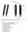
1
EtherStax™ Stackable Industrial I/O Family
Modbus TCP/UDP/IP 10/100MB Ethernet I/O
Model ES2117 Isolated 32 DC IN + 16 AC/DC OUT
USER’S MANUAL
ACROMAG INCORPORATED
30765 South Wixom Road
P.O. BOX 437
Wixom, MI 48393-7037 U.S.A.
Copyright 2007, Acromag, Inc., Printed in the USA.
Data and specifications are subject to change without notice.
Tel: (248) 295-0880
Fax: (248) 624-9234
8500-778-D09A009
2
EtherStax™ ES2117 User’s Manual
Modbus TCP/UDP/IP Isolated I/O
__________________________________________________________________
TABLE OF
CONTENTS
Symbols on equipment:
!
Means “Refer to User’s
Manual (this manual) for
additional information”.
The information of this manual
may change without notice.
Acromag makes no warranty
of any kind with regard to this
material, including, but not
limited to, the implied
warranties of merchantability
and fitness for a particular
purpose. Further, Acromag
assumes no responsibility for
any errors that may appear in
this manual and makes no
commitment to update, or
keep current, the information
contained in this manual. No
part of this manual may be
copied or reproduced in any
form without the prior written
consent of Acromag, Inc.
For additional information,
please visit our web site at
www.acromag.com and
download our whitepaper
8500-765, Introduction To
Modbus TCP/IP, or 8500-648,
Introduction to Modbus.
Windows® is a registered
trademark of Microsoft
Corporation.
IMPORTANT SAFETY CONSIDERATIONS
You must consider the possible negative effects of power, component,
wiring, sensor, or software failure in the design of any type of monitoring or
control system. This is very important where property loss or human life is
involved. It is important that you perform satisfactory overall system design
and it is agreed between you and Acromag, that this is your responsibility.
GETTING STARTED
MOUNTING AND DIMENSIONS………………………
CONTROLS & INDICATORS..…………………………
ISOLATION BARRIERS..……………………………….
CONNECTIONS………………………………………….
Network……………………………………………..
Network Background – Hubs & Switches…….
Redundant Media Connections………………..
Power………………………………………………..
Earth Ground..………………………………….….
Inputs……………………………………………..…
Outputs..……………………………………………
Local Alarm Relay.………………………………..
WEB BROWSER………………………………………...
Home Page…………………………………………
Password Configuration Page.………………...
Network Configuration Page……………………
I/O Configuration Page…………………………..
I/O Mapping Page (i2o Function)………..……..
Test Page…………………………………………..
Utility Page…………………………………………
TROUBLESHOOTING…………………………………..
Diagnostics Table……………………………..….
Getting Out Of Trouble…………………………..
3
10
11
12
12
14
20
22
22
23
23
26
27
27
28
29
32
33
36
37
38
38
41
TECHNICAL REFERENCE
KEY FEATURES…………………………………………
HOW IT WORKS………….……………………………..
ABOUT MODBUS TCP/IP & UDP/IP......……………..
IP Addressing…………..………………………….
MODBUS REGISTERS…………………………………
Register Functions……………………………….
Register Mirroring………………………………..
Data Types…………………………………………
Register Map………………………………………
SPECIFICATIONS……………………………………….
Model Numbers….………………………………..
Mounting Options………………………………...
Inputs - Optocouplers………....…………………
Outputs - Mechanical Relays…..…….…………
Outputs - Alarm Relay……………………………
Enclosure and Physical………………………….
Agency Approvals…..…………………………….
Environmental……………………………………..
Ethernet Interface…………………………………
Controls & Indicators…………………………….
CABLES & CONNECTORS..…….…………………….
42
43
45
48
50
50
51
52
53
58
58
58
59
60
60
61
62
62
64
65
67
_______________________________________________________________________________________
Acromag, Inc. Tel:248-295-0880 Fax:248-624-9234 Email:[email protected] http://www.acromag.com
EtherStax™ ES2117 User’s Manual
Modbus TCP/UDP/IP Isolated I/O
___________________________________________________________________
Units are designed to interlock and stack together up to three units high. A
stack of two or three units can be bolted to a wall or flat surface, or mounted
on deep-channel, “T” type, 35mm x15mm DIN rails (per DIN EN60715
TH35), depending on the optional mounting kit selected. Available mounting
kits are shown below.
8.226
ETHERSTAX DIMENSIONS
DIMENSIONS ARE IN INCHES
A SINGLE UNIT STANDS 2.444 INCHES TALL.
EACH ADDITIONAL UNIT ADDS 2.229 INCHES.
A TWO UNIT STACK IS 4.673 TALL.
A THREE UNIT STACK IS 6.902 TALL.
THE OPTIONAL SURFACE-MOUNT BASE-PLATE
ESA-SMK ADDS 0.25" TO HEIGHT.
THE OPTIONAL DIN RAIL CLIP ESA-DIN-VMK
ADDS 1.0" TO HEIGHT WHEN MOUNTED ON
35mm x15mm DIN RAIL.
THE OPTIONAL BASEPLATE AND HEAVY DUTY
DIN RAIL MOUNT ESA-DIN-HMK ADDS 0.84" TO
HEIGHT WHEN MOUNTED ON 35mm x15mm DIN RAIL.
7.25
6.125
3
MOUNTING AND
DIMENSIONS
These Models are open-type
devices and are intended for
installation into a suitable
enclosure by the end-user.
It is recommended that
enclosed units be panelmounted with the vented
endplates positioned at top
and bottom for improved
cooling. Review the Operating
Ambient Temperature
specification for more
information.
A single unit stands 2.444
inches tall. Each additional
unit adds 2.229 inches.
2.444
A two-unit stack would be
4.673 inches tall. A three-unit
stack is 6.902 inches tall. Add
any additional height as
necessary to account for the
mounting plate, DIN clip, and
DIN rail, if required.
GROUND
SCREW
DIN Rail Vertical Mount Kit ESA-DIN-VMK (One or Two Units): This kit
includes two plastic DIN clips (Rose Bopla #77003500) that slide into the
dove-tail channel of the bottom of the housing. You can use one clip to
mount a single unit, or both for added stability when stacking two units. If
stacking more than two units on a DIN rail, see ESA-DIN-HMK.
TS1
Acromag
TS2
ESA-DIN-VMK TOP VIEW
TS3
COM
ETHERNET 10/100M STATUS
DFT
1
PORT 2
PORT 1
2
RST
I B
NA
0
1
2
3
4
5
6
7
B
8
9
10 11 12 13 14 15
0
1
2
3
4
5
6
7
A
8
9
10 11 12 13 14 15
OB 0
U
T A 0
1
2
3
4
5
6
7
1
2
3
4
5
6
7
ESA-DIN-VMK SIDE VIEW
Position clip such that TOP is aligned
with end of unit you want upright.
TOP should coincide with
the upper lip of the DIN rail
DIN MTG CLIP
OF ESA-DIN-VMK
TOP
This side of clip should
align with top of rail
UPWARD
TO HANG: Tilt unit and place TOP of clip over upper lip
of DIN rail. Press bottom towards rail to snap in place.
TO REMOVE: Push unit upward and tilt TOP of
unit back towards you to disengage it from rail.
NOTE: ESA-DIN-VMK CONTAINS
TWO OF THESE PIECES.
_______________________________________________________________________________________
Acromag, Inc. Tel:248-295-0880 Fax:248-624-9234 Email:[email protected] http://www.acromag.com
4
EtherStax™ ES2117 User’s Manual
Modbus TCP/UDP/IP Isolated I/O
__________________________________________________________________
MOUNTING AND
DIMENSIONS
Simply slide the clips of this kit into the dovetail channel at the bottom of the
enclosure. You can use one clip, or both (recommended), DIN clips of this
kit to mount a single unit. For a stack of two units, both clips must be used.
To remove a unit from the DIN rail, you have to lift the assembly upward and
tilt the top of the unit back to disengage it from the rail. If you choose to
install both DIN clips for added security (recommended), then more pressure
will be required to disengage the unit from the rail. You can also the heavyduty DIN kit model ESA-DIN-HMK to mount a stack of 2 units to a DIN rail.
ETHERSTAX MOUNTING WITH ESA-DIN-VMK
The drawing at right shows
how to mount a unit with the
ESA-DIN-VMK kit.
This kit includes two DIN clips
for added stability, or for
mounting a stack of two units.
Note the orientation of the DIN
clips relative to the rail.
TOP
35mm x15mm
DIN RAIL
To remove a unit from the rail,
grip unit on each side and
pull/push upward while tilting
the top back to release the unit
from the upper lip of the DIN
rail.
IMPORTANT: Stack no more than 2 units with ESA-DIN-VMK.
Use both clips of this kit with two units stacked together.
You can use the ESA-DINVMK to mount a unit such that
its vented endplates are
optimally positioned on top and
bottom as shown at right. Be
sure to use a DIN rail stop to
prevent the unit from moving
along the rail with vertically
mounted DIN rail.
VERTICAL DIN-RAIL MOUNT
USING ESA-DIN-VMK
35mm x15mm DIN RAIL
(Example: IBOCO OMEGA 3AF)
Note that enclosed units
oriented as shown at right will
have improved cooling ability
(see Operating Ambient
Temperature).
USE A DIN RAIL STOP TO
PREVENT MOVEMENT
(Example: IDEC BNL-5)
NOT INCLUDED
UNIT IS SHOWN
MOUNTED USING
BOTH CLIPS OF
ESA-DIN-VMK KIT.
_______________________________________________________________________________________
Acromag, Inc. Tel:248-295-0880 Fax:248-624-9234 Email:[email protected] http://www.acromag.com
EtherStax™ ES2117 User’s Manual
Modbus TCP/UDP/IP Isolated I/O
___________________________________________________________________
Surface-Mount Kit ESA-SMK (One to Three units): This kit includes a
shock-mounted aluminum base-plate and bolts that attach to the bottom of
the housing. Mounting holes with rubber grommets at each corner support
¼-inch bolts for mounting to flat surfaces. Up to three units may be stacked
on this plate.
8.000
0.400"
TYP
ESA-SMK TOP VIEW
5
MOUNTING AND
DIMENSIONS
Insert the four rubber
grommets into the holes at
each corner of the base-plate.
0.400"
TYP
DIN MOUNT
0.089 DIA FOR 4-40
TAP (7 PLACES)
0.266 I.D. x 0.625 O.D. GROMMET
IN 0.406 HOLE (4 PLACES)
OPEN BOARD
MTG HOLES
0.160 DIA
(4 PLACES)
Then use the four ¼-20x0.375,
flat head, counter-sink bolts
provided to bolt this plate to
the bottom of the enclosure.
Be sure to insert the bolts from
the counter-sink side of the
plate.
ENCL MOUNT
0.250 DIA HOLE w/
0.500 DIA x 100 DEG
COUNTER-SINK ON
BOTTOM SIDE
(4 PLACES)
4.00
8.000
4.250
6.675
5.368
0.25
TYP
2.986
1.980
1.923
NOTE VERTICAL OFFSET
OF THIS HOLE COMPARED
TO HOLE AT RIGHT SIDE
1.875
2.000
1.000
0.625
NOTCH FOR
DIN LATCH
Add any additional units to
your stack–you can safely
stack up to three units on this
plate.
Use ¼-inch bolts (not
provided) to bolt this assembly
to a wall or flat surface. It is
recommended that flat
washers (not provided) be
used to protect the rubber
grommet.
2.250
3.291
3.500
4.709
5.750
RUBBER
GROMMET
0.125
ESA-SMK SIDE VIEW
RUBBER
GROMMET
0.375
COUNTER-SINK THIS
SIDE (4 PLACES)
This plate also includes the four holes necessary for mounting an openframe circuit board to it (i.e. no enclosure with hardware of ESA-OMK).
ESA-SMK Kit Contents:
1
4
4
Pre-Drilled Aluminum Base-Plate, 8 x 8 x 0.125.
¼-20 x 0.375 Flat-Head, 100° Counter-Sink, Phillips
Rubber Grommet, 0.625 O.D. x 0.266 I.D
The ¼-inch bolts and washers (recommended) to attach this assembly
to a flat surface or panel are not provided.
For DIN rail mounting of this plate, see ESA-DIN-HMK
_______________________________________________________________________________________
Acromag, Inc. Tel:248-295-0880 Fax:248-624-9234 Email:[email protected] http://www.acromag.com
6
EtherStax™ ES2117 User’s Manual
Modbus TCP/UDP/IP Isolated I/O
__________________________________________________________________
MOUNTING AND
DIMENSIONS
CAUTION: This unit
dissipates notable input power
with high input voltages,
raising the internal ambient
temperature. Mounting
enclosed units such that its
vented endplates are arranged
on top and bottom will allow
this heat to vent more freely.
Review the guidelines
provided in the Operating
Temperature specification
section of this manual.
ETHERSTAX SURFACE MOUNTING WITH ESA-SMK
1
Insert rubber grommet
provided into holes at
each corner of baseplate.
FLAT WASHER REQUIRED, 4 PLACES (NOT INCLUDED)
2
Attach baseplate to
enclosure using four
1/4-20 flat-head bolts
provided. Insert bolts
through counter-sink
side of baseplate.
3
Bolt to wall or flat surface using
1/4 bolts (not provided) at each
corner. Use a flat washer at the
grommet interface as shown.
You will have to temporarily
unplug terminal blocks to
insert bolts through grommet.
DIN Rail Horizontal Mount Kit ESA-DIN-HMK (one to three units): This
kit has the same base-plate as ESA-SMK above, but adds a heavy-duty DIN
adapter (Phoenix UTA-159) and screws for mounting to 35x15mm T-type
DIN rails. Up to three units may be stacked on this plate and mounted to a
DIN rail.
This is the recommended
mounting orientation for
reducing internal heat
generation (see Ambient
Operating Temperature at the
back of this manual).
ETHERSTAX MOUNTING WITH ESA-DIN-HMK
0.10"
35mm x15mm
DIN RAIL
NOTCH FOR ACCESS TO
DIN CLIP RELEASE TAB
(Insert screwdriver here to
pry back spring clamp and
release unit from rail)
ESA-DIN-HMK Kit Contents:
1
Pre-Drilled Aluminum Base-Plate, 8 x 8 x 0.125.
4
¼-20 x 0.375 Flat-Head, 100° Counter-Sink
4
Rubber Grommet, 0.625 O.D. x 0.266 I.D.
1
Heavy-Duty DIN Adaptor (Phoenix UTA-159)
7
4-40 x 0.25 screw with lock-washer
_______________________________________________________________________________________
Acromag, Inc. Tel:248-295-0880 Fax:248-624-9234 Email:[email protected] http://www.acromag.com
EtherStax™ ES2117 User’s Manual
Modbus TCP/UDP/IP Isolated I/O
___________________________________________________________________
To attach or remove the ESA-DIN-HMK to/from the DIN Rail, use a
screwdriver tip inserted into the slot at the end of the DIN clip, in the area of
the notch of the base-plate as shown below. Pry back to compress the DIN
clip spring and release it from the rail. You may have to temporarily unplug
the terminal blocks in the area of this notch to gain access to the DIN clip.
ETHERSTAX ESA-DIN-HMK
REMOVAL FROM DIN RAIL
TS1
TS2
MOUNTING AND
DIMENSIONS
IMPORTANT: Be sure to
remove power before
attempting to disengage unit
from the DIN rail.
Be sure to grip unit firmly
before disengaging unit from
rail and avoid dropping it.
USE A SCREWDRIVER AS SHOWN TO PRY BACK
ON DIN RAIL LATCH AND RELEASE UNIT FROM RAIL.
IT MAY BE NECESSARY TO TEMPORARILY UNPLUG
TERMINAL BLOCKS TO GAIN ACCESS TO DIN LATCH.
Acromag
7
TS3
COM
ETHERNET 10/100M STATUS
DFT
1
PORT 2
PORT 1
2
RST
I B
NA
0
1
2
3
4
5
6
7
B
8
9
10 11 12 13 14 15
0
1
2
3
4
5
6
7
A
8
9
10 11 12 13 14 15
OB 0
U
T A 0
1
2
3
4
5
6
7
1
2
3
4
5
6
7
35mm x15mm
DIN RAIL
LOCATE DIN LATCH IN AREA OF NOTCH IN BASE-PLATE
Note that you can stack up to
3 units on the ESA-DIN-HMK
or ESA-SMK as shown at left.
ETHERSTAX ESA-DIN-HMK STACKING
UP TO 3 UNITS MAY BE STACKED ON A DIN RAIL USING ESA-DIN-HMK AS SHOWN.
7.74"
5.51"
3.28"
0.84"
2.44"
2.29"
2.29"
Subtract 0.59 inches from
dimensions shown if using
ESA-SMK (i.e. no DIN rail
mount).
35mm x15mm
DIN RAIL
0.25"
SUBTRACT 0.59" FROM DIMENSIONS SHOWN IF USING
ESA-SMK BASE-PLATE (NO DIN RAIL MOUNT).
_______________________________________________________________________________________
Acromag, Inc. Tel:248-295-0880 Fax:248-624-9234 Email:[email protected] http://www.acromag.com
8
EtherStax™ ES2117 User’s Manual
Modbus TCP/UDP/IP Isolated I/O
__________________________________________________________________
BUILDING A STACK
MOUNTING AND
DIMENSIONS
The drawing at right shows
how to stack units together.
You can stack up to three units
together in this manner.
SLIDE UPPER UNIT INTO
DOVETAIL CHANNEL OF
LOWER UNIT UNTIL IT
RESTS UPON FRONT
ENDPLATE.
SECURE UNITS
TOGETHER VIA TWO
6-32 SCREWS AT
FRONT, AND ONE
6-32 SCREW AT
CENTER OF REAR
ENDPLATE.
WARNING: Be sure to grip
the edges of unit firmly when
stacking units and avoid
dropping it.
SLIDE UNITS
TOGETHER
1
UPPER UNIT
RESTS ON FRONT
PLATE OF LOWER
UNIT
TS1
Acromag
TS2
TS3
COM
ETHERNET 10/100M STATUS
DFT
1
PORT 2
2
PORT 1
RST
I B
NA
0
1
2
3
4
5
6
7
B
8
9
10 11 12 13 14 15
0
1
2
3
4
5
6
7
A
8
9
10 11 12 13 14 15
TS1
Acromag
ETHERNET 10/100M
OB 0
U
T A 0
1
2
3
4
5
6
7
1
2
3
4
5
6
7
TS2
TS3
COM
STATUS
2
DFT
1
2
PORT 1
2
RST
I B
NA
0
1
2
3
4
5
6
7
B
8
9
10 11 12 13 14 15
0
1
2
3
4
5
6
7
A
8
9
10 11 12 13 14 15
OB 0
U
T A 0
1
2
3
4
5
1
2
3
4
5
6
7
FASTEN UNITS
TOGETHER w/
3 SCREWS AS
SHOWN
SECURE UNITS
TOGETHER VIA TWO
6-32 SCREWS AT
FRONT AS SHOWN,
AND ONE 6-32 SCREW
AT CENTER OF REAR
ENDPLATE.
REAR VIEW
RELAY
STATUS
RUN
8
9
8
9
10 11 12 13 14 15 B O I B 16 17 18 19 20 21 22 23
U
10 11 12 13 14 15 A T N A 16 17 18 19 20 21 22 23
TS4
B
24 25 26 27 28 29 30 31
A
24 25 26 27 28 29 30 31
A
+
-
B
+
-
G
G
PWR
GND
A
+
-
G
B
+
-
RLY
TS6
TS5
RELAY
STATUS
RUN
8
9
10 11 12 13 14 15 B O I B 16 17 18 19 20 21 22 23
U
10 11 12 13 14 15 A T N A 16 17 18 19 20 21 22 23
TS4
TS5
B
24 25 26 27 28 29 30 31
A
24 25 26 27 28 29 30 31
TS6
RLY
_______________________________________________________________________________________
Acromag, Inc. Tel:248-295-0880 Fax:248-624-9234 Email:[email protected] http://www.acromag.com
EtherStax™ ES2117 User’s Manual
Modbus TCP/UDP/IP Isolated I/O
___________________________________________________________________
Open-Board Mounting Kit ESA-OMK: EtherStax units can be ordered and
mounted without their enclosure. This kit includes the jack-screws, and
fasteners necessary to stack two open circuit boards together, plus the
standoffs and screws for mounting this assembly to a flat surface. Note that
this is a replacement kit, as open-frame units already include these items.
Use additional kits as required for stacking more than two boards in this
manner.
ESA-OMK KIT CONTENTS
TOP BOARD
SCREW
#4
6-32x0.25 PAN HEAD SCREWS
#4
1/4-HEX MALE-FEMALE STANDOFF
1-9/16 LONG WITH
6-32 x0.375 FEMALE THREAD &
6-32 x0.250 MALE THREAD
BOTTOM
STANDOFF
#4
1/4-HEX FEMALE STANDOFF
3/8 LONG w/6-32 THREADS
MTG PLATE
SCREW
#4
6-32 x0.25 SEMS SCREW
WITH INTEGRATED WASHER
BD-TO-BD
STANDOFF
IMPORTANT: Models
ordered without their enclosure
are open-type devices and are
intended for installation in a
suitable enclosure by the enduser.
You should take adequate
measures to protect openframe mounted units from
dust, debris, and ESD.
7.500
ETHERSTAX OPEN
FRAME DIMENSIONS
It is highly recommended that
open units be mounted in a
protective enclosure or
cabinet.
DIMENSIONS ARE IN INCHES
STANDOFF MOUNTING - 4 PLACES
4.145
MOUNTING AND
DIMENSIONS
Units ordered without their
enclosure do not retain full
agency approvals, in particular
with respect to ESD protection.
While the open unit retains all
of its built-in transient
suppression and filtering, the
sensitive electronic circuits are
left exposed to ESD damage
without the protection of an
enclosure.
ESA-OMK kit items are also included with every open board assembly.
4.250
(FOUR 0.150 DIA MOUNTING HOLES
WITH 0.280 DIAMETER SHOULDER
AND 0.108 ISOLATION CLEARANCE)
6.000
9
0.25
TYP
0.980
0.875
Note: Open-frame units may
also mount to the optional
surface-mounted base plate
ESA-SMK to facilitate surface
or DIN-rail mounting. This
plate has mounting holes
located as shown to mate with
those of the circuit board.
7.920
Be very careful when handling
open-frame circuits to avoid
ESD damage to the sensitive
circuit components.
OPEN STACK ASSEMBLY (TWO UNITS)
1.875
1.563
0.440
0.375
MTG PLATE
(ESA-SMK)
0.125
_______________________________________________________________________________________
Acromag, Inc. Tel:248-295-0880 Fax:248-624-9234 Email:[email protected] http://www.acromag.com
10
EtherStax™ ES2117 User’s Manual
Modbus TCP/UDP/IP Isolated I/O
__________________________________________________________________
MOUNTING AND
DIMENSIONS
CAT5 CABLE
(NOT INCLUDED)
IP20 SLEEVE
HOUSING
CLAMPS TO FRAME
OF ETHERSTAX
HOUSING
Cable Termination Kit ESA-CTK: The EtherStax enclosure includes a
panel mounted frame around the RJ45 network port that accommodates
special IP20 clip-type plug connectors that help to secure network
connections from shock and vibration. You can still utilize standard RJ45
modular plug connectors, but if you want the added security of this clip
frame, then you have to use the compatible cable plug connectors provided
by this kit. This kit provides the male plug and sleeve housing for one end of
Category 5 Ethernet cable that will mate to this frame. Category 5 cable is
not included. You will also require a modular crimping tool for attaching the
plug to your cable (most standard RJ45 crimping tools will work).
Units ordered without their enclosure cannot utilize this clip.
RJ45 PLUG
ESA-CTK IP20 CAT5
CABLE TERMINATION KIT
CONTROLS &
INDICATORS
Front Panel
Two columns of status
indicators for the network ports
are used to indicate different
things according to whether
the unit is in switch mode, or
hub/repeater mode. Refer to
Specifications – Controls &
Indicators for these definitions.
INPUT PORT 1
(CH00-CH15)
ES2116-0XXX FRONT-PANEL
TS1
Acromag
OUTPUT PORT 1
(CH00-CH07)
TS2
TS3
COM
ETHERNET 10/100M STATUS
DFT
1
PORT 2
PORT 1
2
RST
I B
NA
0
1
2
3
4
5
6
7
B
8
9
10 11 12 13 14 15
0
1
2
3
4
5
6
7
A
8
9
10 11 12 13 14 15
NETWORK PORTS
(10/100M Ethernet)
OB 0
U
T A 0
1
2
3
4
5
6
7
1
2
3
4
5
6
7
DEFAULT/RESET TOGGLE SWITCH
COMMUNICATION STATUS INDICATORS
The toggle switch is used to
toggle the unit into or out of
Default Mode (toggle up & hold
4 seconds), or to reset the unit
(toggle down).
In Default Communication
Mode, the yellow STATUS
LED on the back of the unit will
flash slowly and the unit will
assume a fixed static IP
address of “128.1.1.100”, a
default subnet mask of
“255.255.255.0”, a default
username of “User”, and a
default password of
“password”.
INPUT PORT 1
(CH00-CH15)
ES2116-1XXX FRONT-PANEL
(w/ SC-TYPE FIBER PORT 1)
Acromag
ETHERNET
TS1
OUTPUT PORT 1
(CH00-CH07)
TS2
TS3
100 FX
10/100 T/TX
DFT
Rx
Tx
PORT 2
PORT 1
1 2 RST
I B
STATUS
NA
NETWORK PORTS
100 FX
10/100 T/TX
0
1
2
3
4
5
6
7
B
8
9
10 11 12 13 14 15
0
1
2
3
4
5
6
7
A
8
9
10 11 12 13 14 15
OB 0
U
T A 0
1
2
3
4
5
6
7
1
2
3
4
5
6
7
DEFAULT/RESET TOGGLE SWITCH
COMMUNICATION STATUS INDICATORS
_______________________________________________________________________________________
Acromag, Inc. Tel:248-295-0880 Fax:248-624-9234 Email:[email protected] http://www.acromag.com
EtherStax™ ES2117 User’s Manual
Modbus TCP/UDP/IP Isolated I/O
___________________________________________________________________
ES2116-0XXX BACK-PANEL
POWER/
EARTH GROUND/
RELAY CONNECTIONS
INPUT PORT 2
(CH16-CH31)
OUTPUT PORT 1
(CH08-CH15)
11
CONTROLS &
INDICATORS
Back Panel
The Green RUN LED (bottom)
is ON if power is on and will
blink in “wink” ID mode.
RELAY
STATUS
RUN
8
9
8
9
10 11 12 13 14 15 B O I B 16 17 18 19 20 21 22 23
U
10 11 12 13 14 15 A T N A 16 17 18 19 20 21 22 23
TS4
B
24 25 26 27 28 29 30 31
A
+
-
G
A
24 25 26 27 28 29 30 31
B
+
-
G
TS5
TS6
ALL INPUTS AND OUTPUTS ARE INDIVIDUALLY ISOLATED
The Earth Ground (G) terminals are common
to the enclosure and isolated from I/O, power,
and relay connections.
RLY PWR
GND
UNIT INDICATORS Alarm (Red), Status
(Yellow), and Run
(Green).
The Yellow STATUS LED
(middle) blinks ON/OFF slowly
in default communication
mode and blinks rapidly if a
watchdog timeout has
occurred.
The Red RELAY LED (top) is
ON if relay is energized (relay
terminals A & B are closed).
ISOLATION BARRIERS
RELAY
POWER
GROUND
MODEL ES2117 ISOLATION DIAGRAM
(Dashed Lines Denote Isolation Barriers)
OPTO-COUPLER
INPUTS 16-31
MECH RELAY
OUTPUTS 8-15
Dashed Lines denote isolation
barriers. Additionally, the
enclosure is also isolated.
Channels are additionally
isolated channel-to-channel
(not shown).
GROUND
SCREW
CPU/LOGIC
The inputs, outputs, network
ports (each), power circuit,
relay, and enclosure (earth
ground) are isolated from each
other for safety and noise
immunity.
NOTE: The Ground (G) terminals are
common to the enclosure and isolated
from the power, relay, I/O, and network
circuits for safety and noise immunity.
INPUT CHANNELS ARE
SAFETY ISOLATED TO
250VAC, AND 150V
AC/DC BETWEEN
INPUT CHANNELS.
OUTPUT CHANNELS
ARE INDIVIDUALLY
SAFETY ISOLATED
TO 250VAC.
GROUND
SCREW
Port 2 Port 1
OPTO-COUPLER
INPUTS 0-15
NETWORK
MECH RELAY
OUTPUTS 0-7
Note that the network ports are
individually isolated from the
rest of the circuit and from
each other.
IMPORTANT: Transient
suppression devices are
internally shunted to earth
ground, please connect the
ground terminal to a suitable
earth ground to complete this
path and protect the unit.
Ground may alternately
connect to the ground screw
on either side of the unit
instead of the ground terminal.
_______________________________________________________________________________________
Acromag, Inc. Tel:248-295-0880 Fax:248-624-9234 Email:[email protected] http://www.acromag.com
12
EtherStax™ ES2117 User’s Manual
Modbus TCP/UDP/IP Isolated I/O
__________________________________________________________________
CONNECTIONS
Network
For 100Base-TX systems, at a
minimum, use data grade
Unshielded Twisted-Pair
(UTP) wiring that has a 100Ω
characteristic impedance and
meets the EIA/TIA Category 5
wire specifications.
It is recommended that you
use a CAT-5 cable to connect
this device to your PC.
For 10Base-T systems, you
may use Category 3, Category
4, or Category 5/5E UTP/STP
cable.
In either case, you are limited
to 100 meters between any
two devices.
RJ45 MDI AND MDI-X CONNECTIONS
MDI-X WIRING
PIN MDI WIRING
Receive +
Transmit +
1
Receive Transmit 2
Transmit +
Receive +
3
Not Used
Not Used
4
Not Used
Not Used
5
Transmit Receive 6
Not Used
Not Used
7
Not Used
Not Used
8
ETHERNET PORT
8
1
1
8
CLIP
RJ-45 CONNECTOR
Note Crossover Connections
RECOMMENDED CABLE
SPEED
DISTANCE CABLE
10Base-T
100M
CAT 3, CAT 4, or CAT 5 UTP
CAT 5/5e UTP/STP
100Base-TX
100M
The Ethernet port of this unit is wired MDI-X by default, but includes
automatic crossover (the Ethernet port of your PC is typically wired MDI).
Thus, you can use either a straight-through or crossover cable to connect
this device directly to a PC, Ethernet switch, or another unit.
FRONT OF UNIT
For compatible male plug
connectors, order the Cable
Termination Kit, Acromag
ESA-CTK.
RJ45 Clip Frame
for secure media
connections.
Acromag
COM
ETHERNET 10/100M STATUS
DFT
1
PORT 2
For Compatible
Connectors, see
ESA-CTK Cable
Termination Kit
2
RST
PORT 1
The RJ45 clip frame mates with the compatible
connectors of the ESA-CTK for increased
immunity to shock & vibration.
For increased immunity to shock and vibration, the RJ45 network
connections include special clip frames that can be used with compatible
plug connectors to help secure your network connection from breaking free
under shock or vibration. You can still utilize industry standard RJ45
modular plugs, but if you want the extra security provided by this clip frame,
then you can order compatible connectors via the Acromag ESA-CTK Cable
Termination Kit. This kit includes the male plug and sleeve housing that
mate to the RJ45 frame of the enclosure for one end of CAT5 cable (cable
not included). You will also need a modular plug crimping tool for attaching
the plug provided to your cable.
_______________________________________________________________________________________
Acromag, Inc. Tel:248-295-0880 Fax:248-624-9234 Email:[email protected] http://www.acromag.com
EtherStax™ ES2117 User’s Manual
Modbus TCP/UDP/IP Isolated I/O
___________________________________________________________________
From the factory, EtherStax units have a default IP address setting of
128.1.1.100, and a class C subnet mask of 255.255.255.0. This defines a
restricted default address domain that your current network cannot address
directly, unless you first create an exclusive subnet targeted to the
EtherStax. This typically involves a process by which you either change the
address of your current Network Interface Card (which will temporarily
disable it from your own network), install a second Network Interface Card,
or obtain a free PC or laptop with a NIC installed. In any case, you must set
the address of your network interface card to an address within the default
address domain. That is, an address in the range of 128.1.1.0 to
128.1.1.255, except for 128.1.1.100, which is the default address of the
EtherStax itself. Once you are able to address the unit at its default address,
you can then reconfigure its IP address setting to an address more
meaningful to your existing network. Application Note 8500-734 is
downloadable from the Acromag web site and covers this process in detail.
HOST PC CONNECTED DIRECTLY TO UNIT
Note: This MDI to MDI-X connection does not require a crossover cable.
CAT-5 UTP CABLE
UP TO 100 METERS
(Use Regular or
Crossover Cable)
Host PC w/ Network Interface Card (NIC)
TS1
Acromag
TS2
TS3
COM
ETHERNET 10/100M STATUS
DFT
1
PORT 2
PORT 1
2
RST
I B
NA
0
1
2
3
4
5
6
7
B
8
9
10 11 12 13 14 15
0
1
2
3
4
5
6
7
A
8
9
10 11 12 13 14 15
OB 0
U
T A 0
CONNECTIONS
Before You Connect
Your host PC will require that
a 10/100M network interface
card (NIC) for Ethernet be
installed to connect to the
EtherStax unit. Refer to
Application Note 8500-734, or
document 8500-815, for
information on creating a subnetwork to address the
EtherStax in its default state.
Network – Basic
Connections
You may connect to port 1 or
port 2 of the EtherStax. The
unit is auto-crossing, allowing
you to use a regular or
crossover cable to make
connections.
HOST PC
Connect to
Network
Port 1 or 2
13
1
2
3
4
5
6
7
1
2
3
4
5
6
7
If your unit is a Model ES2117-1xxx, it includes both a 100FX fiber port and a
10BT/100BTX copper port. To connect directly to the fiber port from your
PC, you will need a compatible NIC card installed in your PC, or a media
converter. Note that the auto-crossing feature does not apply to fiber
connections and the Tx and Rx fiber channels must be mechanically
crossed.
IMPORTANT (Fiber Models):
Some models will substitute an
SC-type fiber port connector
for port 1. The auto-crossing
feature of these units does not
apply to the fiber connection
and transmit must be manually
crossed over to receive, and
visa-versa. Facing the front
end-plate of the unit, the
Transmit (Tx) channel is the
bottom half of the SC style
connector, while the top half is
Receive (Rx).
100 FX
Rx
Tx
Optionally, you may use an external Ethernet switch to connect to your
EtherStax unit (recommended). The recommended approach for switched
Ethernet is to connect one unit or Ethernet device per switch port. This is
the most efficient and deterministic method of communication as it increases
network throughput and eliminates data collisions.
_______________________________________________________________________________________
Acromag, Inc. Tel:248-295-0880 Fax:248-624-9234 Email:[email protected] http://www.acromag.com
14
EtherStax™ ES2117 User’s Manual
Modbus TCP/UDP/IP Isolated I/O
__________________________________________________________________
Review the operation of the Com Status LED’s below, which provide useful
information regarding your network connection.
CONNECTIONS
Network LED’s
SWITCH MODE
1
2
HUB/REPEATER MODE
LED Column 1 - Port 1
LED Column 2 - Port 2
1=LED of Column 1
2=LED of Column 2
GREEN
No Function in Switch Mode.
1=Hub Activity, 2=Hub Collision.
COM
STATUS
YELLOW
Link/Activity - ON if Linked/Blinks if Activity.
1=MII/CPU Link/Activity, 2=MII/CPU Error.
YELLOW
Full-Duplex/Collision - ON for Full-Duplex, Blinks for HalfDuplex Collisions, OFF for Half-Duplex and No Collisions.
1=Port 2 Link/Activity, 2=Error at Port 2.
YELLOW
Speed - ON for 100Mbps, OFF for 10Mbps.
1=Port 1 Link/Activity, 2=Error at Port 1.
Refer to Specifications - Controls & Indicators Section for more detail.
The next section reviews the operation of Ethernet hubs and switches as it
relates to the built-in Ethernet switch of this device, which may optionally
operate as an Ethernet hub/repeater. You can skip the next two pages if you
are already familiar with these terms.
Network – Background
Hubs & Switches
To properly network connect
this device, you need to know
a little bit about network hubs
and switches. Please take a
moment to review this material
before installing your unit.
Switched Ethernet involves
connecting one Ethernet
device per switch port. This
suppresses CSMA/CD and
allows the segment to operate
full speed in full duplex. A
throughput of 100M at halfduplex effectively doubles with
full-duplex. This provides a
more reliable and deterministic
communication link, as no data
collisions are possible.
This device has a built-in Ethernet switch that can alternately operate as an
Ethernet hub. To understand which mode to use and how to network
connect Ethernet devices, you need to review switch operation and the
differences between a switch and a hub. If you are already familiar with
these terms, skip over this information and review the various network
connections outlined in the following pages.
An Ethernet hub (or repeater) is a device that simply connects Ethernet
nodes. Any message at one hub port is repeated on all ports. That is, hubs
forward data packets they receive from a single station to all hub ports. As a
result, all port devices connected to a single hub will share the same
bandwidth. Then as nodes are added to the network hub, they compete for
this finite amount of bandwidth (at 10Mbps or 100Mbps). This can cause
data collisions to occur and makes network determinism impossible,
particularly on busy networks. Determinism is a term that is used to
describe the ability to guarantee that a packet is sent or received in a finite
and predictable amount of time. In the past, lack of determinism is the main
reason that Ethernet has had problems being accepted for use in critical
control applications, as most control systems have a defined time
requirement for packet transmission, typically less than 100ms.
An Ethernet switch (or switching hub) is an intelligent device that is used to
more efficiently connect distributed Ethernet nodes than a hub. Unlike a
simple hub, a switch provides targeted data transfer, as it will forward a data
packet to a specific port or network segment, rather than all ports, thus
freeing up bandwidth. The ability to target a packet to a specific port
increases network throughput and helps to eliminate the collisions that
historically make Ethernet non-deterministic.
•
•
•
•
•
Switches act as intelligent repeaters to increase network distance.
Switches split networks into separate collision domains at each port.
Switches provides determinism by reducing collisions.
Switches increase network bandwidth/throughput.
Switches can provide supplemental error checking.
_______________________________________________________________________________________
Acromag, Inc. Tel:248-295-0880 Fax:248-624-9234 Email:[email protected] http://www.acromag.com
EtherStax™ ES2117 User’s Manual
Modbus TCP/UDP/IP Isolated I/O
___________________________________________________________________
With Ethernet, any device can try to send a data frame at any time. The
arbitration protocol for carrier transmission access of the Ether network is
called Carrier Sense Multiple Access with Collision Detection (CSMA/CD). If
two devices happen to send a data frame at the same time, a collision may
occur. With CSMA/CD, each device will first sense whether the line is idle
and available for use. If it is, the device will begin to transmit its first frame.
If another device also tries to send a frame at the same time, then a collision
occurs and both frames are discarded. Each device then waits a random
amount of time and retries its transmission until it is successfully sent.
Unlike other Ethernet devices, such as an Ethernet host adapter or Network
Interface Card (NIC), the port of a switch does not require its own MAC
address. During retransmission of a received packet, the switch port will
instead look like the originating device by having assumed its source
address. This is why the Ethernet collision domain is said to terminate at the
switch port. That is, a two-port switch will effectively break a network into
two distinct data links or segments (also called collision domains). Since all
Ethernet nodes are able to recognize the occurrence of a collision, and since
the detection of a collision is principal to the way Ethernet arbitrates media
access, large domains containing many nodes can become cumbersome.
Thus, using an Ethernet switch to subdivide a large network into separate
collision domains will certainly help to increase throughput. Each port of a
switch forwards data to another port based on the MAC address contained in
the received data packet/frame. In order to know which port to forward a
data packet to, the switch will learn and store the MAC addresses of every
device it is connected to, along with the associated port number (up to 1024
MAC addresses are stored in high speed SRAM). However, until the switch
actually learns the port a particular address resides at (the first packet), it
forwards this traffic to all ports. The switch will use this internal look-up table
to quickly determine the location (port) of a node, establish a temporary
connection between itself and the node, then terminate the connection once
a packet is transferred. In this way, it increases network bandwidth and
provides the network determinism required for critical control applications.
15
CONNECTIONS
Network – Background
Hubs & Switches
The current tendency in critical
industrial control applications
is to connect one Ethernet
device per switch port. This
will produce the most
deterministic mode of
operation as the switch can
operate full-duplex, with no
chance of collisions. This
ensures determinism, helping
critical control applications to
remain predictable and ontime.
Most switches use a store and forward algorithm to process Ethernet
frames. That is, they first store the Ethernet frame and examine it for errors
before forwarding it to its destination. Although in some case this method
may seem to increase the forwarding time (latency) and possibly cause
fragmentation, it can also effectively reduce the occurrence of error frames
and improve overall throughput for most applications. This is particularly
useful where there is heavy network traffic and or greater potential for noise
and interference.
The operative nature of networks causes the rate of data transmission to
vary widely and this variation is referred to as jitter. The optional
hub/repeater mode of this switch provides low-latency network packet
transmission that effectively reduces jitter on the network. Ethernet switches
have higher inherent latency that varies with packet size due to their storeand-forward behavior. Thus, operation in switch mode adds latency and
results in possible latency deviations up to 167us (jitter). In hub-mode, there
is a maximum port-to-port latency of only 310ns with a total deviation of only
40ns. This is because hubs immediately repeat the bits arriving on one port
at their other ports, rather than storing the entire message first before
forwarding it as switches do.
_______________________________________________________________________________________
Acromag, Inc. Tel:248-295-0880 Fax:248-624-9234 Email:[email protected] http://www.acromag.com
16
EtherStax™ ES2117 User’s Manual
Modbus TCP/UDP/IP Isolated I/O
__________________________________________________________________
CONNECTIONS
Network – Background
Hubs & Switches
The current tendency in critical
industrial control applications
is to connect one Ethernet
device per switch port. This
will produce the most
deterministic mode of
operation as the switch can
operate full-duplex, with no
chance of collisions. This
ensures determinism, helping
critical control applications to
remain predictable and ontime.
This sometimes makes hubs more useful for transmission of time-critical
data, or for reducing latency where there is concentrated link traffic (like the
main trunk of cascaded units).
We can also use the hub mode of this switch to implement media
redundancy to this device. That is, if you connect the EtherStax to an
external switch that happens to support media redundancy via a proprietary
ring method, or the Spanning Tree Protocol (STP), or Rapid Spanning Tree
Protocol (RSTP), then the EtherStax unit can be placed in “hub mode” and
you can connect a cable to both ports. The external redundant switch will
sense the redundant path and disable it temporarily. If the primary path
should later fail, then the external switch can reactivate the other path,
effectively providing media failover protection right to the unit.
Note that Acromag offers several industrial managed and unmanaged
Ethernet switch models that can be used to interface to this product (please
consult the factory or visit www.acromag.com).
Some examples of various types of network connections using Ethernet
switches are included in the following pages.
_______________________________________________________________________________________
Acromag, Inc. Tel:248-295-0880 Fax:248-624-9234 Email:[email protected] http://www.acromag.com
EtherStax™ ES2117 User’s Manual
Modbus TCP/UDP/IP Isolated I/O
___________________________________________________________________
The unit includes two Ethernet ports for convenient cascaded network
connections as shown here. This is also useful for extending the network as
each segment may extend up to 100 meters.
17
CONNECTIONS
Network
Note that data collisions are still possible in the first two network segments
shown below as these connections carry the data of more than one unit.
You can isolate each segment and prevent collisions using an external
Ethernet switch connected as shown in the diagram of the following page
(our recommended approach).
HOST PC
Connection may be made to Port 1 or 2
TS1
Acromag
TS2
TS3
COM
ETHERNET 10/100M STATUS
DFT
1
PORT 2
2
PORT 1
RST
I B
NA
0
1
2
3
4
5
6
7
B
8
9
10 11 12 13 14 15
0
1
2
3
4
5
6
7
A
8
9
10 11 12 13 14 15
OB 0
U
T A 0
1
2
3
4
5
6
7
1
2
3
4
5
6
7
You can connect directly to a Host PC with
a NIC installed, or via an Ethernet switch.
CASCADING UNITS
CAT-5 UTP Cable, up to
100 meters per segment
Connections may use Port 1 or Port 2.
Limit cascaded connections to 4 segments.
Limit cable segments to 100M in length.
TS1
Acromag
TS2
TS3
You may use straight-through or
crossover cables.
COM
ETHERNET 10/100M STATUS
DFT
1
PORT 2
2
PORT 1
RST
I B
NA
0
1
2
3
4
5
6
7
B
8
9
10 11 12 13 14 15
0
1
2
3
4
5
6
7
A
8
9
10 11 12 13 14 15
OB 0
U
T A 0
1
2
3
4
5
6
7
1
2
3
4
5
6
7
Units have automatic crossover
and may utilize straight-through
or crossover cables when making
connections.
TS1
Acromag
TS2
TS3
COM
ETHERNET 10/100M STATUS
DFT
1
PORT 2
PORT 1
2
RST
I B
NA
0
1
2
3
4
5
6
7
B
8
9
10 11 12 13 14 15
0
1
2
3
4
5
6
7
A
8
9
10 11 12 13 14 15
OB 0
U
T A 0
1
2
3
4
5
6
7
1
2
3
4
5
6
7
TIP: You can significantly enhance the EMI/RFI performance of your
network connections by using Category 5E STP cable (Shielded Twisted
Pair) cable. The use of shielded cable is strongly recommended for
installations in harsh industrial environments and/or in the presence of
strong electrical fields. For more information on cable, refer to the Cables &
Connectors section at the back of this manual.
_______________________________________________________________________________________
Acromag, Inc. Tel:248-295-0880 Fax:248-624-9234 Email:[email protected] http://www.acromag.com
18
EtherStax™ ES2117 User’s Manual
Modbus TCP/UDP/IP Isolated I/O
__________________________________________________________________
CONNECTIONS
Network
The drawing at right gives our
recommended approach to
making network connections to
the EtherStax via switched
Ethernet.
Here we show one EtherStax
unit connected per switch port.
Thus, each segment is limited
to the traffic of only one device
and no collisions are possible.
This provides the most
deterministic method of
network communication. Only
the segment between the host
and the switch carries the
traffic of multiple units and
collisions are still possible in
this segment.
You can use an Ethernet switch or switching hub to build a network of
Etherstax units, similar to that shown below. The drawing depicts our
recommended approach to distributing I/O via switched Ethernet—that is,
one EtherStax unit is connected per switch port.
(OR PLC/DCS CONTROLLER)
RECOMMENDED CONNECTIONS
(SWITCHED ETHERNET)
SC
FIBER TO REMOTE HOST (UP TO 2KM)
HOST PC
REMOTE HOST
(NIC W/FIBER INSTALLED)
I/O 5
I/O 6
OR
NIC TO SC-TYPE FIBER
MEDIA CONVERTER
I/O 3
CROSSOVER
I/O 4
SC
Acromag
ETHERNET
SWITCH
TX
PWR
R.M.
P8
ACROMAG
EIS-408FX-M
PWR1
RX
PWR2
FAULT
FDX/
COL
LNK/
ACT
TX
P7
RX
P5
R.M.
P8
P7
P6
P5
P4
P3
P2
P1
RESET
P6
P3
P4
P1
P2
EIS-408FX-M
Note that fiber connections
must be crossed over, as the
auto-crossing feature only
applies to copper connections.
OBSERVATION: The extra
copper port of any of these
units can optionally connect to
other network devices, but the
resulting concentrated traffic in
the upstream network segment
would violate the goal of
switched Ethernet which is to
limit the traffic on each
segment to the traffic of one
device, suppressing
CSMA/CD. This is generally
not a problem for a small
number of cascaded units.
For many cascaded nodes, it
is good practice for the
upstream network segment to
use a data rate that is 10x the
data rate of the downstream
nodes, otherwise careful
attention must be paid to
limiting the number of Ethernet
devices that traffic on this
segment.
I/O 1
LOCAL AREA NETWORK
NODES WIRED FOR SWITCHED
ETHERNET (ONE UNIT PER
SWITCH PORT) VIA COPPER
RJ45 CONNECTIONS.
I/O 2
UP TO 100M PER SEGMENT.
The drawing above shows how to network-connect EtherStax units to an 8port Ethernet switch (such as Acromag Model EIS-408FX-M). Note that the
I/O LAN is distributed locally using copper/RJ45 cable connections (up to
100M per segment), and then connected to a remote (distant) host using
fiber cable. The copper connections may use standard or crossover cables,
as both the EtherStax unit and the Ethernet switch include automatic
crossover, but it is generally not considered good practice to use crossover
cables when connecting to an auto-crossing switch.
The switch shown above could be eliminated, if you were connecting to an
EtherStax Model ES2117-1000, which includes one fiber port and one
standard RJ45 port. For example, you could use the fiber port built into the
EtherStax to connect to the distant host using fiber, then add an additional
EtherStax locally via its RJ45 port, similar to that shown on the next page.
However, the traffic of both units would still be concentrated in the main
trunk from the host, and this does not follow the key principle of switched
Ethernet, which seeks to suppress CSMA/CD and prevent data collisions by
connecting only one device per switch port.
_______________________________________________________________________________________
Acromag, Inc. Tel:248-295-0880 Fax:248-624-9234 Email:[email protected] http://www.acromag.com
EtherStax™ ES2117 User’s Manual
Modbus TCP/UDP/IP Isolated I/O
___________________________________________________________________
Unfortunately, you cannot avoid concentrated traffic in the main host
segment, even with a switch. As such, this aggregate path is sometimes
chosen to operate at a higher data rate than the downstream segments.
With the traffic of many Ethernet devices, this would mean that if the main
trunk runs at 100MB, then the downstream nodes should operate at 10MB
(or 100MB if the main trunk was 1Gbps, which the switch of the EtherStax
units does not support). If you cannot easily increase the bandwidth of this
segment, then you should be careful to limit the traffic in this shared
segment by limiting the total number of Ethernet devices connected
downstream.
FIBER TO REMOTE HOST (UP TO 2KM)
ALTERNATE CONNECTIONS
(SWITCHED ETHERNET WITH
TWO NODES)
SC
OR
NIC TO SC-TYPE FIBER
MEDIA CONVERTER
NOTE:
I/O 1 IS THE ES2113-1000,
WHICH HAS ONE PORT OF
FIBER, AND ONE PORT OF
COPPER.
ALL ETHERSTAX UNITS HAVE
A BUILT-IN ETHERNET SWITCH.
THUS, THIS CONNECTION RETAINS
THE BENEFITS OF SWITCHED
ETHERNET FOR TWO UNITS.
I/O 1
SC
ETHERSTAX HAS
AN ETHERNET
SWITCH BUILT-IN
CROSSOVER
I/O 2
CONNECTIONS
Network
The drawing at left gives an
alternate method for
connecting to a remote host,
while still retaining the benefit
of switched Ethernet between
two nodes.
HOST PC
REMOTE HOST
(NIC W/FIBER INSTALLED)
MODEL ES2113-1000
(One Copper Port and one Fiber Port)
19
LOCAL AREA NETWORK
NODES WIRED FOR SWITCHED
ETHERNET (ONE UNIT PER
SWITCH PORT) VIA COPPER
RJ45 CONNECTIONS.
UP TO 100M PER SEGMENT.
CAUTION: YOU SHOULD LIMIT THE NUMBER
OF CASCADED CONNECTIONS, AS THIS WILL
INCREASE THE CONCENTRATION OF TRAFFIC
IN THE CUT-THROUGH PATH WITH THIS
CONNECTION.
CASCADED
COPPER
CONNECTION
For optimum performance, the ideal recommended approach is to utilize an
external Ethernet switch and connect no more than one Ethernet device per
switch port—this is what is referred to as switched Ethernet. Connection in
this manner avoids the negative effects of concentrated traffic and
suppresses the need for collision detection. This effectively allows a
segment to operate in full-duplex at the fastest possible speed. Thus, the
throughput of 100M at half-duplex, can effectively approach 200MB when
operating at full-duplex for switched Ethernet.
Although the connection shown above still retains the benefit of switched
Ethernet without utilizing an external switch, it really only applies to the first
two nodes. If you wanted to connect more than two nodes, but still retain the
benefits of switched Ethernet, you would have to utilize an external Ethernet
switch and connect one EtherStax unit per switch port.
This still adheres to the
principles of switched Ethernet
because the network ports of
the EtherStax are provided by
an internal 3-port Ethernet
switch.
However, note that the fiber
connection carries the traffic of
both units and this segment is
subject to data collisions.
Likewise, if you add a third
unit, I/O3, cascaded from I/O
2, then the first copper
segment carries the burden of
the traffic of I/O 2 and I/O 3.
This would not promote the
benefit of switched Ethernet in
this segment where we
attempt to limit the traffic on a
switched segment to a single
device and suppress the need
for CSMA/CD.
WARNING: Never use the
EtherStax as a bridge device
connected in series within your
enterprise LAN, as the effect
of concentrated traffic in the
shared segment could inhibit
communication to/from your
EtherStax unit.
Ideally, the shared segment
link that carries the
concentrated 100Mbps traffic
should operate at a higher
data rate, like 1Gbps, which
this switch does not support
_______________________________________________________________________________________
Acromag, Inc. Tel:248-295-0880 Fax:248-624-9234 Email:[email protected] http://www.acromag.com
20
EtherStax™ ES2117 User’s Manual
Modbus TCP/UDP/IP Isolated I/O
__________________________________________________________________
CONNECTIONS
Network
Although it may be possible to cascade more than two additional EtherStax
units (3 units), it is recommended that the number of units connected in this
fashion be limited to 3 total (the recommended physical height of a single
stack of EtherStax units), as shown in the following drawing.
TO NIC
TO NIC
HOST PC
HOST PC
REMOTE HOST
(w/ NIC INSTALLED)
REMOTE HOST
(w/ NIC INSTALLED)
OPTIONAL CONNECTIONS
(TWO CASCADED NODES)
RECOMMENDED CONNECTIONS
(SWITCHED ETHERNET)
UNITS ARE AUTO-CROSSING
AND DO NOT REQUIRE A
CROSSOVER CABLE WHEN
MAKING COPPER NETWORK
CONNECTIONS
CONNECT TO
PORT 1
Acromag
A
TS1
ag
TS2
TS3
TX
PORT 2
2
RST
PORT 1
E1 8
9
10 11 12 13 14 15 E2 24 25 26 27 28 29 30 31
E3 40 41 42 43 44 45 46 47
R
1
2
R 16 17 18 19 20 21 22 23
R 32 33 34 35 36 37 38 39
TS2
TS3
0
3
4
5
6
7
TS1
Acromag
LNK/
ACT
P7
1
PORT 2
2
1
CASCADE
PORT 2 TO
PORT 1
2
RST
P6
P3
P4
PORT 1
E1 8
9
10 11 12 13 14 15 E2 24 25 26 27 28 29 30 31
E3 40 41 42 43 44 45 46 47
R
0
1
2
R 32 33 34 35 36 37 38 39
E1 8
9
10 11 12 13 14 15 E2 24 25 26 27 28 29 30 31
E3 40 41 42 43 44 45 46 47
R
1
2
R 32 33 34 35 36 37 38 39
3
4
5
6
7
TS1
R 16 17 18 19 20 21 22 23
P1
P2
TS2
1
TS3
PORT 2
2
PORT 1
RST
PORT 1
E3 40 41 42 43 44 45 46 47
R
1
2
R 16 17 18 19 20 21 22 23
R 32 33 34 35 36 37 38 39
0
3
4
5
6
7
TS1
TS2
TS3
E1 8
9
10 11 12 13 14 15
E2 24 25 26 27 28 29 30 31
E3 40 41 42 43 44 45 46 47
R
0
1
2
7
R 16 17 18 19 20 21 22 23
R 32 33 34 35 36 37 38 39
TS2
TS3
E1 8
9
10 11 12 13 14 15
E2 24 25 26 27 28 29 30 31
E3 40 41 42 43 44 45 46 47
R
1
2
R 16 17 18 19 20 21 22 23
R 32 33 34 35 36 37 38 39
3
4
5
6
TS1
Acromag
EIS-408FX-M
COM
ETHERNET 10/100M STATUS
DFT
PORT 2
E2 24 25 26 27 28 29 30 31
DFT
Acromag
2
TS1
COM
ETHERNET 10/100M STATUS
COM
ETHERNET 10/100M STATUS
1
10 11 12 13 14 15
RESET
P5
DFT
PORT 1
RST
Acromag
COM
ETHERNET 10/100M STATUS
PORT 2
TS3
9
DFT
R.M.
P8
P7
P6
P5
P4
P3
P2
P1
TX
RX
TS2
E1 8
Acromag
COM
ETHERNET 10/100M STATUS
PWR2
FAULT
FDX/
COL
1
CONNECT ONE UNIT
PER SWITCH PORT
PWR1
RX
DFT
CASCADE
PORT 2 TO
PORT 1
PWR
R.M.
P8
COM
STATUS
ETHERNET
RST
DFT
0
3
4
5
6
7
R 16 17 18 19 20 21 22 23
USE AN ETHERNET
SWITCH TO DISTRIBUTE
NODES
1
PORT 2
PORT 1
2
RST
0
3
4
5
6
7
PERMISSIBLE
OPTIMUM
LIMIT THIS CONNECTION TO
TWO CASCADED UNITS AS SHOWN
(MOST DETERMINISTIC)
Again, for the most deterministic approach, utilize an Ethernet switch and
distribute connections as one Ethernet device per switch port as shown in
the above right drawing.
Network –
Redundant Media
Connections (Optional)
Recommended for
High-Reliability
Applications
When the EtherStax network
port is placed in hub/repeater
mode, it can support media
redundancy right to the node if
connected to a redundant
switch as shown at left.
TO NIC
HOST PC
REMOTE HOST
(w/ NIC INSTALLED)
OPTIONAL
NODE REDUNDANCY
CONNECTIONS
IN HUB MODE, THE ETHERSTAX
REPEATS ANY MESSAGE ON A PORT
AT THE OPPOSITE PORT, TRIGGERING
THE EXTERNAL SWITCH TO SENSE
THE REDUNDANT PATH, DISABLE IT,
AND HOLD IT AS A BACKUP PATH
SHOULD THE PRIMARY PATH FAIL.
I/O 1
REDUNDANT
SWITCH
REQUIRED
Acromag
TX
PWR
R.M.
P8
PWR1
RX
PWR2
FAULT
FDX/
COL
LNK/
ACT
TX
P7
RX
R.M.
P8
P7
P6
P5
P4
P3
P2
P1
RESET
P5
P6
P3
P4
P1
P2
EIS-408FX-M
USE AN ETHERNET
SWITCH TO DISTRIBUTE
NODES
CONNECT TWO
PATHS TO UNIT
IMPORTANT: THE UNIT MUST
BE IN HUB-MODE PRIOR TO
CONNECTING THE SECOND
NETWORK PATH TO PREVENT
MESSAGE LOOPS FROM
DEVELOPING.
Note: The EtherStax fiber port does not operate in hub mode and cannot be
used in redundant path applications.
_______________________________________________________________________________________
Acromag, Inc. Tel:248-295-0880 Fax:248-624-9234 Email:[email protected] http://www.acromag.com
EtherStax™ ES2117 User’s Manual
Modbus TCP/UDP/IP Isolated I/O
___________________________________________________________________
This device has dual Ethernet ports provided by a built-in Ethernet switch.
Normally the second port connection provides a convenient cascaded
network connection, or is used for extending the network, or to provide
media conversion. But this integrated switch also has an alternate operating
mode as a hub/repeater. As a hub, anything sent in one port is immediately
transmitted out at the other port. This adds much lower latency. Additionally
in this mode, if you connect both ports of this device to a redundant switch,
or redundant switch network, the external switch will sense the redundant
path and automatically disable the second path to this device, holding it as a
backup in case of primary path failure. This behavior is completely managed
by the redundant switch, making the EtherStax compatible with current
proprietary media redundant ring methods, Spanning Tree (STP), or Rapid
Spanning Tree (RSTP), but limited to half-duplex operation (hubs are halfduplex devices).
21
CONNECTIONS
Network –
Redundant Media
Connections (Optional)
Recommended for
High-Reliabilty
Applications
The figure below depicts the EtherStax unit connected to a redundant switch
media ring. Here we use an Acromag EIS408FX-M switch to build the ring
which supports redundant ring. The EtherStax unit must be placed in
hub/repeater mode prior to making these connections. Connected this way,
the EtherStax looks just like an Ethernet hub to the ring and operates
transparent to the media ring. The redundant path fail-over and recovery are
managed entirely by the external switch.
Acromag
TX
SWITCH
PWR
R.M.
P8
PWR1
RX
PWR2
FAULT
FDX/
COL
LNK/
ACT
TX
P7
RX
P5
R.M.
P8
P7
P6
P5
P4
P3
P2
P1
RESET
P6
P3
P4
P1
P2
EIS-408FX-M
ACROMAG
EIS-408FX-M
REDUNDANT MEDIA
RING CONNECTIONS
ACROMAG
EIS-408FX-M
ACROMAG
EIS-408FX-M
IF PRIMARY PATH LATER FAILS,
THEN RING WILL FAIL-OVER TO
THE ALTERNATE PATH.
Acromag
Acromag
TX
TX
PWR
RX
PWR2
LNK/
ACT
TX
P7
RX
R.M.
P8
P7
P6
P5
P4
P3
P2
P1
RESET
P5
P6
P3
P4
FDX/
COL
LNK/
ACT
TX
SWITCH
SWITCH
P7
RX
P5
P2
EIS-408FX-M
EIS-408FX-M
DISABLED PATH
(SWITCH BLOCKS
COMMUNICATION
VIA REDUNDANT
PATH)
P4
P1
P2
R.M.
P8
P7
P6
P5
P4
P3
P2
P1
RESET
P6
P3
P1
PWR2
FAULT
FAULT
FDX/
COL
PWR
PWR1
PWR1
RX
R.M.
P8
R.M.
P8
ETHERSTAX UNIT
I/O 1
THE ETHERSTAX IS
TRANSPARENT TO
THE RING IN HUB
MODE
UNIT MUST BE IN
HUB/REPEATER
MODE
_______________________________________________________________________________________
Acromag, Inc. Tel:248-295-0880 Fax:248-624-9234 Email:[email protected] http://www.acromag.com
22
EtherStax™ ES2117 User’s Manual
Modbus TCP/UDP/IP Isolated I/O
__________________________________________________________________
Power
9
CAUTION: Do not Exceed
36VDC peak.
Use a Class 2 power source from 18-36V DC and connect to the power
terminals PWR + and PWR – while observing proper polarity. Optionally
connect redundant backup power to the second set of terminals. For
supply connections, use No. 14 AWG wires rated for at least 75°C.
DC POWER CONNECTIONS
REDUNDANT POWER (18-36V DC)
Input Power ES2117-0
Voltage
Current
18VDC
260mA
24VDC
191mA
36VDC
130mA
18-36VDC
+
RELAY
STATUS
Input Power ES2117-1
Voltage
Current
18VDC
334mA
24VDC
250mA
36VDC
167mA
Above is maximum power with
all relays energized.
As a rule, your supply should
be capable of providing at
least twice the maximum
current draw of the unit (for
inrush). Your series fuse
should also be minimum rated
for greater than twice this
current also.
Earth Ground
Warning: To comply with
safety and performance
standards, use shielded cable
and connect earth ground as
noted. Failure to use good
wiring and grounding practices
may be unsafe and hurt
performance.
18-36VDC
+
RUN
A
+
-
G
B
+
-
G
RLY PWR
GREEN RUN LED
(Indicates Power ON)
OBSERVE PROPER POLARITY
GND
INPUT POWER IS ISOLATED
AND REVERSE POLARITY
PROTECTED
EARTH GROUND
Each of the power inputs is series diode-coupled, providing reverse polarity
protection and allowing external redundant drive. You cannot use the
second set of power terminals to cascade power to other units because of
this diode. With redundant power connections, the higher connected voltage
will carry the load, and if that supply later fails, the lower voltage supply will
carry the load.
CAUTION: Risk of Electric Shock – More than one disconnect switch may
be required to de-energize equipment before servicing.
IMPORTANT – External Fuse: If this unit is powered from a supply capable
of delivering more than 3A to the unit, it is recommended that current to the
unit be limited via a high surge tolerant fuse rated for a maximum current of
4A or less (for example, see Bel Fuse MJS series). Failure to limit peak
input current can damage the transient protection (shunt) of the input power
terminals for sustained surge or continuous over-voltage conditions.
9
Connect Earth Ground as shown in the connection drawings for best
results. Additionally, connect the unit’s GND terminal (G) to earth
ground as shown above. Alternately, you may utilize the earth ground
screw at each side of the enclosure to complete the earth ground path.
In some cases, additional earth grounding is recommended at your I/O.
If sensors are already grounded, use caution and avoid adding ground
connections which could create ground loops. If your loads happen to
be conducting higher currents, or are displaced more than a few feet
from the unit, it may be necessary to make these ground connections
local to the I/O return terminals for improved transient response.
The enclosure is common to the ground terminals and isolated
from the other circuits. Transient energy is shunted to this ground
via isolation capacitors and transient voltage suppressors. You
must connect earth ground to complete this path and ensure
protection. Additional earth grounds may be recommended at
some I/O return leads (see connection drawings).
_______________________________________________________________________________________
Acromag, Inc. Tel:248-295-0880 Fax:248-624-9234 Email:[email protected] http://www.acromag.com
EtherStax™ ES2117 User’s Manual
Modbus TCP/UDP/IP Isolated I/O
___________________________________________________________________
9
Connect input signals to the input terminals as shown below. Inputs are
DC voltages equal or below 32V.
ES2117 DC input ON range is
20-32VDC. Do not exceed
32VDC.
+3.3V
INPUT PORT 1A
B
-
+
DC Inputs are polarized with A
input treated positive and B
input treated as negative.
A
+
B
0
1
2
3
4
5
6
7
A
0
1
2
3
4
5
6
7
CONNECTIONS
Inputs
DC-VOLTAGE LEVEL DETECTION
+
23
16 INPUT CHANNELS/PORT
250VAC ISOLATED
150VAC ISOLATED CHANNEL-TO-CHANNEL
DC INPUT ON RANGE IS 20-32VDC.
DC INPUT CONNECTIONS ARE POLARIZED WITH A POSITIVE, B NEGATIVE.
INPUT CHANNELS ARE ISOLATED FROM EACH OTHER TO 150V AC/DC AND 0.063 INCHES MINIMUM.
INPUTS (AS A GROUP) ARE ISOLATED TO 250VAC AND 0.108 INCHES MIN.
9
Outputs – DC Loads
Connect your load to the output A & B terminals as shown below.
RELAY OUTPUT CONNECTIONS - DC LOADS
Outputs are not polarized.
OUTPUT ISOLATION
LOCATE SHUNT DIODE D
NEAR INDUCTIVE LOAD L
SIMPLIFIED OUTPUT
(ONE PORT CHANNEL)
OUTPUT PORT 1A
SPST-NO
D
L
LOAD
V
S
30VDC/2A
CPU
B
0
1
2
3
4
5
6
7
A
0
1
2
3
4
5
6
7
16 OUTPUT CHANNELS/PORT
250VAC ISOLATED
OUTPUT CONTACTS ARE 1 FORM A (SPST).
OUTPUTS ARE EACH ISOLATED TO 250VAC AND 0.108 INCHES MINIMUM.
OUTPUT IS RATED TO 2A AT 30VDC FOR GENERAL USE.
NOTE REVERSE SHUNT DIODE ADDED WITH INDUCTIVE LOADS.
Ratings: 2ADC maximum in
this application. Output relays
are rated for 3A at 30VDC/
250VAC general use.
Different ratings apply to the
Alarm Relay (see Local Alarm
Relay).
Add reverse connected diodes
across inductive loads to shunt
potentially high reverse
voltages that develop when
the output is switched OFF.
DC LOADS: 2A maximum, in this application. Output contacts themselves
are rated for 3A at 30VDC/250VAC, general use, but limited to 2A in this
application. Optionally, you can use an interposing relay to raise your
voltage & current drive capability (see below).
IMPORTANT – Add Shunt Diode With Inductive Loads: Output wiring
should include reverse-bias shunt diodes located near inductive loads. This
diode will shunt the potentially high reverse-bias voltage generated when
switching the inductive load and prevent this transient energy from being
sent along the connection wires. It also minimizes radiated emissions.
Place a diode across the inductive load (1N4006 or similar) with the cathode
to (+) and the anode to (-).
_______________________________________________________________________________________
Acromag, Inc. Tel:248-295-0880 Fax:248-624-9234 Email:[email protected] http://www.acromag.com
24
EtherStax™ ES2117 User’s Manual
Modbus TCP/UDP/IP Isolated I/O
__________________________________________________________________
CONNECTIONS
Outputs – DC Loads
LOAD GROUNDING: If your load is connected at some distance from the
unit, or your load currents are high, earth grounding the return lead should
be done local to the I/O terminals of the unit to allow the built-in transient
protection to effectively shunt to earth via a low impedance path not affected
by IR losses.
USE OF AN INTERPOSING RELAY: You can optionally drive an
interposing relay in order to raise the output voltage and current drive
capability further by connecting the unit similar to that shown below.
INTERPOSING RELAY CONNECTIONS - DC
YOU CAN CONTROL AN INTERPOSING RELAY IN ORDER TO DRIVE HIGHER
CURRENT AND HIGHER VOLTAGE LOADS SIMILAR TO THAT SHOWN HERE.
TYPICAL DIN-RAIL MOUNTED RELAY
OUTPUT PORT 1A
3
2
SIMPLIFIED OUTPUT
(ONE PORT CHANNEL)
OUTPUT ISOLATION
CONTACT
PROTECTION
1
4
SPST-NO
DC RELAY
POWER
8
5
DIODE
CPU
7
6
+
LOCATE RELAY NEAR LOAD
USE REVERSE-BIAS SHUNT DIODES ACROSS INDUCTIVE LOADS TO EXTEND CONTACT LIFE.
B
0
1
2
3
4
5
6
7
A
0
1
2
3
4
5
6
7
16 OUTPUT CHANNELS/PORT
250VAC ISOLATED
YOUR DC APPLICATION VOLTAGE AND CURRENT PRODUCT MUST NEVER
EXCEED THE MAX POWER RATING.
Output – AC Loads
When switching inductive
loads it is good practice to
have a contact rating that is 23x the steady-state
requirements of the load.
Utilize Metal-Oxide Varistors or
AC-rated capacitors to shunt
potentially high reverse
voltages that develop across
inductive loads when the
output is switched OFF.
RELAY OUTPUT CONNECTIONS - AC LOADS
OPTIONAL PROTECTION
(INDUCTIVE LOADS)
C
OUTPUT ISOLATION
SIMPLIFIED OUTPUT
(ONE PORT CHANNEL)
OUTPUT PORT 1A
(HI SIDE)
AC
LOAD
SPST-NO
(LO SIDE)
V
S
CPU
B
0
1
2
3
4
5
6
7
A
0
1
2
3
4
5
6
7
16 OUTPUT CHANNELS/PORT
OUTPUT CONTACTS ARE 1 FORM A (SPST).
OUTPUTS ARE EACH ISOLATED TO 250VAC AND 0.108 INCHES MINIMUM.
250VAC ISOLATED
OUTPUT IS RATED 2A AT 250VAC, GENERAL USE. YOUR APPLICATION
VOLTAGE MUST NOT EXCEED THE 250VAC SAFETY ISOLATION RATING OF THIS UNIT.
THE CONTACT RATING SHOULD BE 2-3X THE STEADY-STATE REQUIREMENTS OF THE INDUCTIVE LOAD.
USE CAPACITORS (AC) AND SHUNT DIODES (DC) ACROSS INDUCTIVE LOADS TO EXTEND CONTACT LIFE.
AC LOADS: 2A maximum, in this application. Output contacts themselves
are rated for 3A at 30VDC/ 250VAC general use, but limited to 2A in this
application. Optionally, you can use an interposing relay to raise your
voltage & current drive capability further (see below).
_______________________________________________________________________________________
Acromag, Inc. Tel:248-295-0880 Fax:248-624-9234 Email:[email protected] http://www.acromag.com
EtherStax™ ES2117 User’s Manual
Modbus TCP/UDP/IP Isolated I/O
___________________________________________________________________
Inductive loads can be very hard on relay contacts and generally have violent
startup voltage and ampere requirements that exceed the steady-state
requirements. For example, an electric motor or transformer would be an
inductive load. As such, inductive loads typically require 2-3x the runtime
voltage or current when power is first applied to the device. It is good policy
to select your switch contact voltage and ampere ratings 2-3x the nominal
steady-state requirements of your load. Choosing a relay that is 2-3x more
powerful than your rated application is the best way to extend the life of relay
contacts.
25
CONNECTIONS
Outputs – AC Loads
Inductive Load Ratings:
With respect to inductive
loading of outputs, use
General Use ratings of 2A at
30VDC/ 250VAC.
Additionally, the use of capacitors, metal-oxide varistors, or RC snubbers will
help to shunt voltage transients away from relay contacts and extend their
life when switching inductive loads.
INTERPOSING RELAY CONNECTIONS - AC
YOU CAN CONTROL AN INTERPOSING RELAY IN ORDER TO DRIVE HIGHER
CURRENT AND HIGHER VOLTAGE LOADS SIMILAR TO THAT SHOWN HERE.
TYPICAL DIN-RAIL MOUNTED RELAY
CONTACT
PROTECTION
OUTPUT ISOLATION
AC RELAY
POWER
8
MOV
5
SPST-NO
W
1
4
3
2
OUTPUT PORT 1A
CPU
7
6
L1
LOCATE RELAY NEAR LOAD
USE A METAL-OXIDE VARISTOR ACROSS AC INDUCTIVE LOADS TO
SUPPRESS TRANSIENTS AND EXTEND CONTACT LIFE.
B
0
1
2
3
4
5
6
7
A
0
1
2
3
4
5
6
7
16 OUTPUT CHANNELS TO A PORT
250VAC ISOLATED
YOUR AC APPLICATION VOLTAGE AND CURRENT MUST NOT
EXCEED 250VAC/2A, GENERAL USE.
CONTACTS THAT SWITCH INDUCTIVE LOADS SHOULD BE RATED 2-3X GREATER
THAN THE APPLICATION STEADY-STATE POWER REQUIREMENTS.
_______________________________________________________________________________________
Acromag, Inc. Tel:248-295-0880 Fax:248-624-9234 Email:[email protected] http://www.acromag.com
26
EtherStax™ ES2117 User’s Manual
Modbus TCP/UDP/IP Isolated I/O
__________________________________________________________________
Local Alarm Relay
This relay is programmable as
failsafe (normally energized),
or non-failsafe (normally deenergized) via the Local Relay
Failsafe/Non-failsafe Selection
Register, or I/O Configuration
web-page.
The relay LED indicates the
energized state (ON).
You can choose to activate
this relay upon watchdog
timeout only, or watchdog
timeout and communication
link loss conditions.
If you select failsafe contacts,
then you can also use this
relay to signal a power failure
(contacts de-energize when
power fails).
9
The local alarm relay contacts are located adjacent to power and labeled
A & B. Connect to these contacts the same as was illustrated for the
output relays of this model, while observing ratings below.
These contacts are switched for conditions of media failure (link loss),
watchdog timeout, or power failure (failsafe only). Contacts are normally
open type (de-energized), but software configurable as failsafe (normally
energized), or non-failsafe (normally de-energized).
The alarm contacts are rated to 2A in this application. Alarm relay is
rated for 3A at 30VDC/240VAC general use. For control of higher
energy devices, an interposing relay may be used and is connected the
same as shown for the output relays.
ALARM RELAY CONNECTIONS - DC LOAD
ISOLATED ALARM RELAY
RED RELAY LED
(Indicates A & B
Energized State)
A
B
Contacts are SPST-NO
(1 Form A) and rated to
3A at 240VAC/30VDC
General Use. Limit
maximum current to
2A in this application.
RELAY
STATUS
RUN
A
+
-
G
B
+
-
G
RLY PWR
EARTH GROUND
LOAD
2A/30VDC
TO
125VDC/0.48A
+
GND
250VAC ISOLATED
IMPORTANT: External contact protection is generally required for
switching inductive loads. This may require that you add a reverse bias
shunt diode across your inductive load. Refer to the examples given for
the output relays. Failure to use adequate protection may reduce the life
of the contacts or damage the unit.
This equipment is suitable for use in Class I, Division 2, Groups A, B,
C, and D, or non hazardous locations only.
WARNING – EXPLOSION HAZARD – Do not disconnect unit while circuit is
live, unless the area is known to be free of ignitable content.
WARNING – EXPLOSION HAZARD – Substitution of any components may
impair suitability for Class I, Division 2.
WARNING – Exposure to some chemicals may degrade the sealing
properties of the materials used in the sealed relay devices of this unit.
RECOMMENDATION – It is recommended to periodically inspect the sealed
relay devices of this unit and check for any degradation of the materials and
to replace the complete product, not just the sealed device, if any
degradation is found.
_______________________________________________________________________________________
Acromag, Inc. Tel:248-295-0880 Fax:248-624-9234 Email:[email protected] http://www.acromag.com
EtherStax™ ES2117 User’s Manual
Modbus TCP/UDP/IP Isolated I/O
___________________________________________________________________
This unit supports Modbus over TCP/IP and UDP/IP (a TCP/IP message will
get a TCP/IP response, while a UDP/IP message will get a UDP/IP
response). You may use your own software to issue Modbus commands to
this device (see Modbus Registers), or you may use a standard web
browser, as these units have built-in web pages that allow you to setup and
control their operation. Simply execute your web browser, type the IP
address assigned to your unit in the “Address” window (http://128.1.1.100/
for our example), click [Go], and you will be presented with the Home Page
window of the unit similar to that shown below:
27
WEB BROWSER
Home Page
The Home Page provides buttons to access the other web pages of this unit
that are used to configure the network parameters, change the user name
and password, configure the I/O, and operate the unit. Note that not all
parameters are programmable with Modbus commands issued to Modbus
registers. In general, you would still have to use the embedded web pages
to complete your configuration (for example, the network configuration
parameters do not have Modbus registers).
For details on various operating modes, please refer to the command
descriptions of the Modbus Memory Map.
For each new browser session that accesses the Home Page of this unit,
you will be presented with a window prompting you to enter the current User
Name and Password as shown on the next page. This information is
required before the program will allow you to make any other selections.
The default user name and password is “User” and “password”
respectively. After entering these defaults, you should invoke the Password
Configuration Page to change these parameters to something more
meaningful for you.
_______________________________________________________________________________________
Acromag, Inc. Tel:248-295-0880 Fax:248-624-9234 Email:[email protected] http://www.acromag.com
28
EtherStax™ ES2117 User’s Manual
Modbus TCP/UDP/IP Isolated I/O
__________________________________________________________________
WEB BROWSER
Home Page
IMPORTANT: If you forget your
user name and password, you can
always toggle the unit into default
mode via the DFT default mode
toggle switch at the front of the unit
(hold this toggle 4 seconds to
invoke default mode). In this mode,
the password and username will
revert to the original defaults noted
above, allowing you to re-invoke the
Password Configuration Page and
change the username and
password as required.
Password
Configuration Page
Note: Your password is limited
to 10 characters. If you
exceed 10 characters, your
password will only be set to
the first 10 characters you
typed. This will become
painfully apparent to you when
you attempt to gain access
later.
Use up to 20 alphanumeric characters (case sensitive) to specify your
username, and 10 alphanumeric characters (case sensitive) to specify a
password. You will have to type in these entries twice to help prevent errors.
Click the submit button to write your changes to the unit.
After completing your username/password changes, click on the appropriate
button at the bottom of the page to select another web page. If you
happened to have made changes, you may be prompted again to re-enter
your new username and password before being permitted to move to the
other web pages. Just be sure to use the new values you just set.
If you ever forget your username & password, you can always put the unit in
default mode via its DFT mode switch, address it at its default mode address
128.1.1.100, and then change the password to something you can
remember.
_______________________________________________________________________________________
Acromag, Inc. Tel:248-295-0880 Fax:248-624-9234 Email:[email protected] http://www.acromag.com
EtherStax™ ES2117 User’s Manual
Modbus TCP/UDP/IP Isolated I/O
___________________________________________________________________
After setting your username and password, you can click the “Network
Configuration Page” button and a screen similar to that shown on the
following page will appear. Use this screen to set the network configuration
parameters for your unit (these parameters cannot be set via Modbus
registers). You may have to consult your network administrator for help in
completing the contents of this page.
29
WEB BROWSER
Network Configuration
Note that Acromag Series
ES2100 Ethernet I/O devices
may take from 3 to 30 seconds
to boot upon power-up,
depending on your network
configuration and whether a
DHCP server is present.
An IP Address is a unique identification number for any host (this unit) on
any TCP/IP network (including the internet). The IP address is made up of
four octets (8 bits), each octet having a value between 0-255 (00H-FFH). It
is expressed here in decimal form, with a period placed between octets.
A Static IP Address is as the name implies—static, and represents a unique
fixed IP Address that is generally assigned by your service provider or
system administrator. The Default Mode static IP address assigned to this
unit is 128.1.1.100 (refer to the product side label).
This device can be placed into
a default communication mode
via the DFT toggle switch at
the front of the unit.
IMPORTANT: The default Class C subnet mask setting of 255.255.255.0
and our default IP address of 128.1.1.100 leave only 255 possible addresses
that a host PC could assume in order to initially talk to the unit. That is, your
PC’s network interface card will have to be set to a node address in this
domain range in order to initially talk to the EtherStax.
Default Mode uses a static IP
address of “128.1.1.100”, a
default subnet mask of
“255.255.255.0”, a default
username “User”, and a
default password “password”.
NOTE: In order to network your PC with an EtherStax unit, you may have to
consult with your network administrator and either temporarily change your
TCP/IP configuration (see TCP/IP Properties of Network Configuration in
Windows), or create a separate private network using a second network
adapter installed in your PC (recommended). The necessary steps will vary
with your operating system. Refer to Acromag Application Note 8500-734,
or document 8500-815, for help doing this (located on the CDROM shipped
with your unit or via download from our web site at www.acromag.com).
_______________________________________________________________________________________
Acromag, Inc. Tel:248-295-0880 Fax:248-624-9234 Email:[email protected] http://www.acromag.com
30
EtherStax™ ES2117 User’s Manual
Modbus TCP/UDP/IP Isolated I/O
__________________________________________________________________
WEB BROWSER
Network Configuration
Note that the Number of
Sockets limitation does not
restrict access via Modbus
UDP/IP, only TCP/IP, as UDP
is a connectionless protocol.
The Number of Sockets refers to the number (1-10) of Modbus TCP/IP
access points to allow for this host (via port 502 reserved for Modbus). You
can restrict access by reducing this number. If this unit is a target i2o device
(i2o output), do not set this number below 2, as i2o will consume one TCP/IP
socket.
Gateway refers to the IP Address of the gateway, if your local area network
happens to be isolated by a gateway. Typically, it is assigned the first host
address in the subnet. If a gateway is not present, then this field should
contain an unused address within the host subnet address range.
A Subnet Mask is used to subdivide the host portion of the IP address into
two or more subnets. The subnet mask will flag the bits of the IP address
that belong to the network address, and the remaining bits correspond to the
host portion of the address. The unique subnet to which an IP address
refers to is recovered by performing a bitwise AND operation between the IP
address and the mask itself, with the result being the sub-network address.
The Active IP Address refers to the current IP Address being used by this
host, as opposed to any new assignments being made via this page.
The MAC Address refers to the Media Access Control address that uniquely
identifies the MAC hardware of this device. This is a unique fixed address
assigned to the MAC at its manufacture. It is not to be confused with the
dynamically assigned 32-bit IP Address, commonly denoted as four 8-bit
numbers separated by periods (e.g. 128.1.1.100). Every manufacturer
producing Ethernet hardware, has by assignment, a series of 48-bit
addresses to use. They are restricted to use only the addresses in their
series, and only one time, thus ensuring that no two computers in the world
will ever have the same MAC address.
An Ethernet packet will include two 48-bit address fields appended to it that
represent the MAC addresses of the sending computer, and the destination
computer. In IEEE 802 networks, the Data Link Control (DLC) layer of the
OSI Reference Model is divided into two sublayers: the Logical Link Control
(LLC) layer, and the Media Access Control (MAC) layer. It is the MAC layer
that interfaces directly with the network media (each different type of network
media requires a different MAC layer) and where this address distinction is
applied.
By default, the unit is setup to use Static IP Addressing and a Static IP
Address of 128.1.1.100. You can optionally choose to have the IP address
assigned dynamically via DHCP/BOOTP, or DHCP/BOOTP w/Fallbacks.
This will also require that you specify a valid Host Name. Note that
DHCP/BOOTP w/Fallback will revert to the static IP address if your DHCP or
BOOTP server cannot be found at the address specified.
In general, BOOTP (BOOTstrap Protocol) refers to an internet protocol that
enables a diskless workstation to discover its own IP address, the address of
a BOOTP server on the network, and a file to be loaded into memory to boot
the machine. This enables the workstation or device server to boot without
requiring a hard or floppy disk drive. BOOTP works similar to DHCP, but is
usually found in older systems. This protocol is defined by RFC 951.
_______________________________________________________________________________________
Acromag, Inc. Tel:248-295-0880 Fax:248-624-9234 Email:[email protected] http://www.acromag.com
EtherStax™ ES2117 User’s Manual
Modbus TCP/UDP/IP Isolated I/O
___________________________________________________________________
DHCP (Dynamic Host Configuration Protocol) refers to a protocol for
assigning dynamic IP addresses to devices on a network. With dynamic
addressing, a device can have a different IP address every time it connects
to the network. In some systems, it can even change while it is still
connected. DHCP also supports a combination of static and dynamic IP
addresses. DHCP/BOOTP with fallback will revert to static IP addressing if
the DHCP or BOOTP server cannot be found.
The unit includes a default address toggle switch to cause the unit to
assume a fixed default static IP address (128.1.1.100). This switch is at the
front of the unit and is used to toggle the unit into, or out of Default Mode. If
you use the toggle switch at the front of the unit to place the unit in default
mode, then “Default Communications Mode” will be indicated at the bottom
of this screen.
31
WEB BROWSER
Network Configuration
The Default Communication
Mode uses a static IP address
of “128.1.1.100”, a default
subnet mask of
“255.255.255.0”, a default
username of “User”, and a
default password of
“password”.
For the Ethernet port controls, you can select that speed and duplex be autonegotiated (recommended), or you may force the speed to 10Mbps or
100Mbps, and the duplex to half or full. However, full duplex communication
will not be possible unless CSMA/CD is suppressed via a switched Ethernet
connection at the port. Further, on units that have a fiber-optic SC type
connector for port 1, only 100Mbps operation at full-duplex is possible. Note
that the port status is displayed just below these fields.
For the mode control, this unit is set to “Switch” by default, but may optionally
be set to “Hub”. Hub mode is useful to reduce latency on the network, or to
setup redundant media connections to this device. You should review the
information regarding hubs and switches in the Network Connections section
of this manual for help discerning the difference between a switch and a hub,
and information on redundant media connections. Refer to the Technical
Reference section of this manual to learn more about Modbus, TCP, UDP,
and IP Addressing terms and concepts.
Click the Submit button to complete any changes made on this page.
Click the Wink On/Off button to toggle the unit in/out of “wink” ID mode. In
this mode, the unit’s green RUN LED will blink to confirm identification and
address setting.
_______________________________________________________________________________________
Acromag, Inc. Tel:248-295-0880 Fax:248-624-9234 Email:[email protected] http://www.acromag.com
32
EtherStax™ ES2117 User’s Manual
Modbus TCP/UDP/IP Isolated I/O
__________________________________________________________________
WEB BROWSER
I/O Configuration Page
After completing the username/password assignment, plus the network
configuration parameters, you can use the I/O Configuration Page to setup
your outputs and the local alarm relay. This model has one output port of 16
channels, and one local alarm relay.
When you first enter a page
that includes controls like the
Write Configuration button of
this page, you may note that
your first click on a control is
ignored. This is because the
first click activates the control,
while the next click executes
the function.
Once you have carefully made
your selections, click the
“Write Configuration” button at
the bottom of the page to
activate your configuration
(reconfiguration takes effect
immediately following “Write
Configuration”).
Refer to the following definitions and the Modbus Memory Map for
information on optional modes of operation:
Output Functions
Output WD Time (seconds) – Enter 1-65534 seconds to set a watchdog
time period for port outputs, or 65535 to disable the watchdog timer. If no
write activity occurs to any channels of the port over this period, a watchdog
timeout occurs and the watchdog flag for the port is set in the unit’s Status
Register. Additionally, you can direct the unit to set its port outputs to a predefined state upon watchdog timeout, or do nothing (see below).
Output WD State (16 bit Hex Value) – Upon watchdog timeout, you can
direct the unit to set its port outputs to this pre-defined state with “Take
Action” also selected, or do nothing to the outputs with “No Action” selected.
You must enter four hex digits that represent the bit settings for the 16
channels of the port. The lsb corresponds to the lowest numbered channel
of the port, the msb to the highest numbered channel.
“0” = 0000, “1”= 0001, “2” = 0010, “3” = 0011, “4” = 0100, “5” = 0101, “6” =
0110, “7” = 0111, “8” = 1000, “9” = 1001, “A” =1010, “B” = 1011, “C” = 1100,
“D” = 1101, “E” = 1110, “F” = 1111.
For example, enter “FFFF” to turn all port outputs ON following timeout.
_______________________________________________________________________________________
Acromag, Inc. Tel:248-295-0880 Fax:248-624-9234 Email:[email protected] http://www.acromag.com
EtherStax™ ES2117 User’s Manual
Modbus TCP/UDP/IP Isolated I/O
___________________________________________________________________
Output Normally Energized/Normally De-energized – This control sets
the 0=OFF or normal state of the output port relays to either energized
(closed), or non-energized (open). Mechanical relay contacts of this model
are closed in the energized state. The simulated LED’s of the Test Page are
ON to indicate an output in the 1=ON state. If energized is selected, then
immediately after power-up the outputs will transfer to the energized (closed)
state.
33
WEB BROWSER
I/O Configuration Page
Alarm Relay (For Output Watchdog Timeout & Link Loss)
This unit includes a separate set of SPST contacts at the input power
terminal block (labeled A & B). If you select “Failsafe”, the alarm contacts
will be normally energized (closed), and de-energize (open) upon alarm. If
you select “Non-Failsafe”, the contacts will be normally de-energized (open),
and energize upon alarm (close). The “Relay” LED of this unit always
indicates that these contacts are energized (closed), irrespective of the
failsafe/non-failsafe configuration
This relay can be triggered only upon a watchdog timeout if “Watchdog
Timeout Only” is selected, or additionally upon a link loss condition at the
network ports if “Watchdog Timeout and Link Error” is selected. Disable the
watchdog timer if you want the alarm relay to only be triggered by a link loss
condition. Note that both network ports must be inactive to generate a linkloss error (i.e. no communication possible).
TIP: Selecting “Failsafe” will
allow the unit to additionally
signal a power-loss condition
as the contacts will open when
power is lost.
This unit includes special remote messaging functionality called i2o, input-tooutput communication. This allows an i2o source to send its digital input
port data to an output port on another ES2117, or an ES2113 model. You
can even use i2o to map input port 2 data to the output port of the same unit.
Optionally, inverted input port data may be sent to an output port. The i2o
Mapping page shown below is used to specify the static IP address of the
targeted remote ES2117/2113 unit(s). You can elect to send this units input
port data to the target unit cyclically at the update rate specified, or upon
change-of-state. Optionally, you can send inverted input data to a target
output port. That is, a 1=ON input event at this unit can be setup to turn the
output of a remote unit ON, or OFF when inverted.
I/O Mapping Page
(i2o Function)
IMPORTANT: The i2o mapping feature maps the same input port and
channel numbers, to identically numbered port and channel numbers of a
remote unit (i.e. the same register/coil number). By design, ES2117 units
have two input ports and only one output port. As such, only input port 1
may be mapped to another ES2117 unit. Input port 2 cannot map to another
ES2117, as these models do not have an output port 2. But input port 2 of
these models can optionally map to output port 2 of a model ES2113, or it
can map locally to the output port of itself, but this is not the same as i2o.
_______________________________________________________________________________________
Acromag, Inc. Tel:248-295-0880 Fax:248-624-9234 Email:[email protected] http://www.acromag.com
34
EtherStax™ ES2117 User’s Manual
Modbus TCP/UDP/IP Isolated I/O
__________________________________________________________________
WEB BROWSER
I/O Mapping Page
(i2o Function)
Note: The i2o mapping
feature may only be configured
via the built-in web browser
page as there are no Modbus
registers for specifying these
parameters.
While this unit supports
Modbus TCP/IP and UDP/IP,
i2o messages are only sent via
Modbus TCP/IP.
The i2o messaging will
consume one TCP/IP socket
on the target device.
The i2o target device must
have a static IP address in
order to process i2o
messages.
WARNING: These models use mechanical relay contacts as their output
channels. Mechanical relays have a finite contact life and will wear out
eventually, especially if controlled under highly cyclical conditions or at a high
frequency. Consider this carefully with respect to your application and avoid
using mechanical contacts in applications that require frequent contact
transfer. Your application may instead require the use of relay sockets, or
solid-state switches, and you should consult the factory for options in this
regard.
These units have 2 ports of 16 input channels, and 1 port of 16 output
channels. Input Port 1 refers to input channels 0-15 (front-side), Input Port 2
refers to input channels 16-31 (back-side), and Output Port 1 to output
channels 0-15 (8 front-side and 8 back-side). Input port 1 of this unit may be
mapped to an output port of another ES2117 unit, or to output port 1 of
separate ES2117 units (it could also map to output port 1 of an ES2113
unit). Input port 2 of this unit can only map to output port 2 of an ES2113
unit, as there is no output port 2 on ES2117 units. Because target output
ports of these models are mechanical relays, carefully consider their finite
contact life and avoid frequent contact transfer (see Warning above).
This page also allows you to locally map input port 2 to output port 1 on the
same unit. This is not i2o, but is similar enough to include its configuration
on this page. However, in this case, the channel-to-channel mapping is
done bit-wise (not with respect to maintaining same port and contact-to-coil
number).
The digital input states may be transferred cyclically, or upon change of
state. However, if you select change-of-state, you will still need to specify a
cyclic update rate in order to keep the communication socket open and
prevent a timeout if your change of state transitions happen to occur at
intervals greater than 90 seconds apart.
_______________________________________________________________________________________
Acromag, Inc. Tel:248-295-0880 Fax:248-624-9234 Email:[email protected] http://www.acromag.com
EtherStax™ ES2117 User’s Manual
Modbus TCP/UDP/IP Isolated I/O
___________________________________________________________________
If you select a time of 0 with change-of-state enabled, a default value of 30
seconds will be used to ensure the connection remains open (i2o uses
TCP/IP which is a connection-oriented protocol). You may want to make the
update time longer to conserve network bandwidth while still preventing a
timeout. If you disable change of state, then your output control messages
will occur at every interval of your update time (0 disables cyclic messaging).
IMPORTANT: This module is designed to function as a Modbus TCP/IP
slave/server. Normally, Modbus servers are not allowed to initiate messages
on their own and may only respond to client/master requests. The i2o
functionality of this unit is a special application that may cause confusion for
some master/client devices linked to the same network. To avoid problems,
other master devices on the network should be restricted from attempting to
control i2o target devices. You can also make use of the “Number of
Sockets” parameter to limit access to an i2o target device.
Note that i2o inputs only map externally, and always map the corresponding
input-contact to output-coil number and at the same target port number
(same channel-to-channel position of same port), but individual input ports
may be mapped to separate output ports of different units (at different IP
addresses). The target output port must be another ES2117 or ES2113
model.
Subsequent messages will be sent at a periodic rate specified via the update
time. Note that the target output port channels may still be controlled
independently, but their state will be overwritten by subsequent mapped i2o
messages when this feature is enabled. To avoid problems, it is
recommended that you do not attempt to separately control the mapped
output ports directly.
Change-of-State: Set ON to enable remote updates on change of input
state, and OFF to update cyclically. With change-of-state enabled, you will
still have to specify an update time less than or equal to 90 seconds in order
to keep the communication socket open and prevent a timeout of the
connection. If you select 0 seconds with change-of-state enabled, a default
value of 30 seconds will be used to ensure the connection remains open.
Invert Sent Data (i2o only): If you want the ON state of the inputs to
instead turn the i2o target outputs OFF, then select “Yes” to Invert Sent
Data. This will send a “0” to the output when the input is “1”, and a “1” when
the input is “0”. This does not apply to local input-to-output mapping.
Update Time: Specify a time from 0-90 seconds between messages.
Specify 0 to turn i2o messaging OFF (cyclical). If change-of-state is set to
ON, a default time of 30 seconds will be used to keep the connection open.
Map To IP Address: This is the Static IP Address of the target output
device (another ES2117 unit on the network). Either digital input port may
be mapped to an output port, both to separate output ports at two different IP
addresses, but never both to the same output port.
Map Input Port 2 To Internal Output Port 1 (This is not i2o): This works
similar to i2o, except locally (within the same unit) and will send this units
input port data word (16-bits) to this unit’s output port data word (16-bits)
when “Yes” is selected. Note that this action still allows the same port inputs
to control one or two remote output ports of an ES2113 model. The Invert
Sent Data control does not apply to local mapping.
35
WEB BROWSER
I/O Mapping Page
(i2o Function)
This messaging function works
best if the target unit(s) are
already online and ready to
receive messages. It will still
work if the target output units
come online after the input
units, but may take several
minutes to “discover” the
network targets and begin
transmitting to them.
Likewise, if the input unit or the
target unit(s) go offline, remote
messaging will resume on its
own when the connection is
re-established, but this
“healing” function may take
several minutes depending on
which device(s) went offline,
why, and for how long.
IMPORTANT: If your i2o input
unit utilizes the invert sent data
control for the port, the
inverted state of the input port
is instead sent to the i2o
target, but this does not affect
the state of the simulated Test
Page LED for the input level
which is always ON for an
active-high input level.
Note that if you happen to
perform the procedure for
restoring a unit to its original
configuration as outlined in the
“Getting Out Of Trouble”
section of this manual, all of
the mapping variables are
returned to their default values
and mapping may have to be
reconfigured.
_______________________________________________________________________________________
Acromag, Inc. Tel:248-295-0880 Fax:248-624-9234 Email:[email protected] http://www.acromag.com
36
EtherStax™ ES2117 User’s Manual
Modbus TCP/UDP/IP Isolated I/O
__________________________________________________________________
Test Page
When you first enter a page
that includes controls like this,
you may note that your first
click on a control is ignored.
This is because the first click
activates the control (yes, this
was deliberately inserted to
annoy you).
After completing the username/password assignments, plus the network and
I/O configuration parameters, you can click the Test Page button to access
the Test Page and operate your EtherStax unit. Here you are able to read
the input states, toggle output states, and even set a polling rate.
The simulated input and output
LED’s of this page always
reflect the 1= ON state when
turned ON.
Inputs of this model are always
active-high and the simulated
input LED’s of this page reflect
the high state of the input
signal when lit.
Note that i2o includes an
optional inversion control that
allows you to invert the input
logic sent to an i2o target, but
this does not affect the state of
the simulated Test Page LED
indicators.
However, the output port can
be configured as normallyenergized, or normally deenergized, and this setting
determines the 0=OFF state of
the output contacts.
The button below the output
LED’s can be used to toggle
the output between states.
Note that output contacts of
this model are closed in the
energized state.
TIP: You can use the mouse
to point and click on a control
to toggle the corresponding
output on/off, or you can use
the spacebar to toggle the last
output control you pointed to.
Note that the 48 channels of this unit are divided into 3 groups (ports) of 16
channels each. Input Port 1 refers to input channels 0-15, Input Port 2 refers
to input channels 16-31, and Output Port 1 to output channels 0-15.
Inputs of this model are always active-high. The state of an input channel is
indicated by a simulated red LED below the channel number (bright red for a
high voltage input signal).
A status message is displayed that tells you whether i2o is enabled at a port,
and whether i2o inversion is enabled.
The state of an output is indicated by a simulated green LED below the
channel number (bright green for the 1=ON state of the output relay). To
change the state of an output channel, simply click the white control button
below the output LED to toggle the corresponding output state, as required.
Note that port outputs may be configured as normally energized or normally
de-energized (relay contacts of this model are closed when energized) and
this refers to the 0=OFF state of the contacts. The simulated output LED
ON always represents the ON=1 state of the output.
You can speed-up or slow-down the I/O polling rate by clicking and dragging
the polling rate slide control at the bottom of the Test Page screen (rate
varies from 500ms to 10000ms, rightmost setting disables polling).
_______________________________________________________________________________________
Acromag, Inc. Tel:248-295-0880 Fax:248-624-9234 Email:[email protected] http://www.acromag.com
EtherStax™ ES2117 User’s Manual
Modbus TCP/UDP/IP Isolated I/O
___________________________________________________________________
A watchdog timeout is triggered at the output port if no output channel write
occurs for one or more output channels of the port within the time period
specified. You can use the Port Watchdog Timer Control to specify Time
from 0001H to FFFEH seconds (1 to 65534s). A time value of 0000H or
FFFFH (0 or 65535) will disable the timer for the port I/O. You can also
define the state the outputs are to assume following a timeout. Outputs can
be set as normally energized, or normally de-energized. Enter a state value
of “0” to turn OFF all port outputs upon watchdog timeout (set it to the
normal state). Enter “1” to turn all port outputs ON upon watchdog timeout
(set it to the alarm state). Note that OFF/ON follows the convention of the
simulated output LED of the test page (this LED is on for the set state, but
the set state may be set as energized or de-energized).
37
WEB BROWSER
Test Page
TIP: Note that an i2o input source may optionally invert its i2o logic sent to
an i2o target, which would mimic the same effect as selecting normally
energized outputs on the i2o target device. Be aware of this when setting up
i2o if your expected output state is opposite what you planned.
You may also access a Utility Page that includes a couple of built-in utilities
that allow you to verify basic input and output operation to the I/O controller,
without wiring to the I/O (self-test control). A second utility will allow you to
export your current configuration to another unit (export configuration
control). You can select the Utility Page button from the Test Page screen to
display a screen similar to that shown here:
Utility Page
When you first enter a page
that includes controls like this,
you may note that your first
click on a control is ignored.
This is because the first click
only activates the control.
_______________________________________________________________________________________
Acromag, Inc. Tel:248-295-0880 Fax:248-624-9234 Email:[email protected] http://www.acromag.com
38
EtherStax™ ES2117 User’s Manual
Modbus TCP/UDP/IP Isolated I/O
__________________________________________________________________
WEB BROWSER
Utility Page
I/O Self Test Control
The I/O self-test feature of this page takes advantage of the separate input
and output port controllers of this device to test I/O operation without having
to do any wiring. This is a useful trouble-shooting aide if you are
experiencing problems. Simply click the Start Self Test button to check I/O
operation. Note that it will not actually drive the output relays and upset your
wired control strategy, as these lines are tri-stated during this test. This
affects a test of the I/O controllers, internal registers, and SPI bus.
Export Configuration Control
Enter the IP address of the destination unit you are trying to replicate this
configuration at. The destination unit must be already connected to the
network. Refer to Network Connections for examples of how to network
connect units.
The export function is a real time-saver when commissioning multiple units
in similar fashion. Simply enter the IP address of the unit you wish to send
your I/O configuration to (it is assumed that you have already communicated
with it and setup its network parameters at this point). Click the Export
Configuration button to transmit your I/O configuration. With reference to the
Modbus Memory Map for this device, this function sends the contents of all
Holding Registers (4xxxx registers), right up to the wink register, to the IP
address indicated (it does not send network configuration parameters which
must be preset via the web browser). The Export Status window will let you
know if the configuration was received correctly or not at the remote I/O
station.
TROUBLESHOOTING
Diagnostics Table
SYMPTOM…
POSSIBLE CAUSE
Green RUN LED Does Not Light…
Bad connections.
Try a system reset.
Internal +3.3V power has failed or
a fatal processor (firmware) error
has occurred.
Input Power TVS has failed. This
could occur for a sustained voltage
surge or continuous over-voltage
at the power terminals.
Unit Fails to Start-up or Initialize…
Input power voltage below 18V
minimum?
Input power source is currentlimiting on the turn-on inrush.
Cannot Browse Unit…
Your browser may be setup to use
a proxy server for LAN
communications.
POSSIBLE FIX
Recheck Power Connections
Use the RST toggle to reset the unit.
Return unit for repair.
Return unit for repair. Power should
be fused externally or current-limited
to a safe operating level no less than
twice the maximum input current.
Check your power supply voltage and
make sure that it is at least 18V.
Although units will continue to
operate if this voltage drops below
18V, they will not start reliably for
voltages below 18V.
Your supply should be capable of
providing at least 2x the maximum
current draw of the unit.
Temporarily disable the use of a
proxy server by your browser (see
procedure of next page).
_______________________________________________________________________________________
Acromag, Inc. Tel:248-295-0880 Fax:248-624-9234 Email:[email protected] http://www.acromag.com
EtherStax™ ES2117 User’s Manual
Modbus TCP/UDP/IP Isolated I/O
___________________________________________________________________
SYMPTOM…
POSSIBLE CAUSE
Cannot Browse Unit…
Have you set the address of your
Network Interface Card to an
address within the address domain
of your EtherStax unit?
POSSIBLE FIX
Review your IP address setting and
subnet mask and compare them to
the IP address of your network
interface card. Refer to Application
Note 8500-734 for more information
on setting up your network
connection.
Temporarily disable the use of a
Your browser may be setup to use
proxy server by your browser (see
a proxy server for LAN
procedure of next page).
communications.
Continuous Flashing Green RUN LED…
Unit was not connected to network The RUN LED will continue to blink
upon power-up, or network cable is as the unit hunts for a network link.
Connect a network cable to the unit
bad.
to complete its initialization.
Unit in “wink” mode.
Read Unit Status register to verify
“wink” status. Write 5555H to Wink
Mode Toggle Register to toggle wink
mode off/on.
Unit failed to boot firmware.
A continuously flashing green Run
LED can signify the unit has failed to
initialize and may require repair if you
are sure you have a good network
connection and proper power voltage.
Cannot Communicate…
Power ON to the unit?
Check if green RUN LED is ON?
Fiber Connections not crossed
The auto-crossing feature does not
over.
apply to the fiber port. These
connections must physically cross
transmit to receive and visa-versa.
Wrong IP Address
Change IP address of the unit or host
PC so they both match. Try the
default unit address of 128.1.1.100.
Many Communication Errors…
Is cable segment longer than
Distance between two Ethernet
100M?
nodes is generally limited to 100
meters with approved copper cable,
or 2000 meters with multi-mode fiber
cable.
Correct Cable?
Shielded CAT-5/5E copper cable or
equivalent is recommended.
Missing earth ground connection.
Connect earth ground to TS6 GND
terminal adjacent to power terminal.
Inputs Not Reading Back Correct OFF State…
Inputs do not return to their OFF state
The input level may have not
dropped below the hysteresis level until the level has dropped below the
hysteresis.
of the input.
39
TROUBLESHOOTING
Diagnostics Table
…continued
Upon power-up, after blinking
momentarily, the green “Run”
LED should remain ON. This
indicates the unit is properly
powered and operating
normally. If RUN continues to
blink, then the unit may not be
connected to the network or
the cable is bad. Otherwise, a
continuous blinking RUN LED
can indicate unit is in “wink” ID
mode, or it may be indicative
of a firmware initialization
error.
_______________________________________________________________________________________
Acromag, Inc. Tel:248-295-0880 Fax:248-624-9234 Email:[email protected] http://www.acromag.com
40
EtherStax™ ES2117 User’s Manual
Modbus TCP/UDP/IP Isolated I/O
__________________________________________________________________
TROUBLESHOOTING
Diagnostics Table
…continued
If your problem still exists after
checking your wiring and
reviewing this information, or if
other evidence points to
another problem with the unit,
an effective and convenient
fault diagnosis method is to
Exchange the unit with a
known good unit. Acromag’s
Application Engineers can
provide further technical
assistance if required.
Complete repair services are
also available from Acromag.
SYMPTOM…
POSSIBLE CAUSE
Outputs Stopped Working…
The outputs of this model are
mechanical relays, have a finite
life, and are not intended for highly
cyclical OFF/ON processes.
POSSIBLE FIX
Your relay may be worn out and
require replacement. To switch loads
rapidly, at high frequency, or over
many cycles, you need solid-state
control—consult the factory for
options in this regard. Compatible
sockets are also available for these
relays.
Redundancy Failover Protection Not Occurring…
Your unit’s network configuration is Set the unit to hub/repeater mode
not in hub/repeater mode.
(not switch mode) for redundant
media applications.
Repeated System Resets Occur with Redundant Port Connections…
Use an external redundant switch to
Your external network or switch is
connect to both ports of this device at
not setup to handle redundant
the same time.
media connections.
Fiber Port Not Communicating…
Auto-crossing does not apply to fiber
Is fiber cable crossed over?
connections, which must physically
Have you selected 100MB and
crossover the transmit and receive
Full-Duplex for fiber port 1?
channels. Further, the fiber port
Note the Tx channel of the unit is
communicates at 100Mbps only and
the bottom half of the SC fiber
auto-negotiation is not possible. It
connector, while the Rx channel is
does not operate in hub/repeater
the top half (facing front of unit).
mode.
If you reconnected fiber cable and
Have you disconnected/
link signals are present, but you still
reconnected fiber cable? A reset
cannot talk to unit, then you must
may be required.
reset the unit to recover
communications.
Communication To Unit is Lost…
Was communication interrupted by Reset the unit via the RST toggle or
severe interference or shock?
by cycling power.
i2o Target Not Turning ON with Input…
Have you inverted the input signal
If inputs are inverted, the inverted
with the polarity inversion control?
logic signal is sent to the i2o target.
Use the i2o port inversion control to
reverse the logic inversion.
i2o Target set to opposite state expected…
Have you doubly-inverted the input An i2o input source may optionally
invert the i2o logic sent to an i2o
signal with both the input polarity
target. This can mimic the effect of
inversion control and the output
selecting normally energized outputs
normally energized/normally
on the i2o target device. If both are
energized selection?
done together, the result is a double
inversion of the input.
i2o Target not being set by i2o input…
Only input port 1 may map to output
Have you inadvertently mapped
port 1, as the ES2117 only has one
input port 2 to output port 1 of
output port 1. Input port 2 can map to
another ES2117 unit?
I/O port 2 of an ES2113.
_______________________________________________________________________________________
Acromag, Inc. Tel:248-295-0880 Fax:248-624-9234 Email:[email protected] http://www.acromag.com
EtherStax™ ES2117 User’s Manual
Modbus TCP/UDP/IP Isolated I/O
___________________________________________________________________
41
Refer to Acromag Application Note 8500-734 for help in setting up network
communication with your unit (see CDROM shipped with unit or down-load it
from www.acromag.com). This document gives details for changing your
PC’s TCP/IP configuration in order to communicate with hardware similar to
your unit (see TCP/IP Properties of Network Configuration in Windows).
TROUBLESHOOTING
If you have carefully followed this procedure and you still cannot browse your
unit, have you set the IP address of your host network interface card to an
address within the address domain of the EtherStax? For example, the
default Class C subnet mask setting of 255.255.255.0 and the default IP
address of 128.1.1.100 leave only 255 possible addresses that a host PC
could assume in order to initially talk to the unit. Otherwise, you may have
the web browser of your laptop or PC setup to use a proxy server when
browsing the web. If you are using Internet Explorer, refer to the “Tools”
pull-down menu, select “Internet options…”, click the “Connections” tab, then
click the “LAN Settings” button. Locate the Proxy server information and
uncheck the box next to the statement “Use a proxy server for your LAN”.
Then click [OK] to return to the “Connections” screen, and click [OK] again to
save your settings. You should now be able to use Internet Explorer to
browse the unit as required. However, to later restore your PC’s connection
to your company network, you may have to re-enable the use of a proxy
server for your LAN.
Trouble Browsing Your
Unit?
There is limited built-in error checking to prevent you from writing invalid
values to a configuration register, and if you inadvertently write an invalid
value to an internal register, operation may become unpredictable under
certain conditions. If resetting the unit ever fails to restore order, then in
order to regain control of the unit, the unit can either be re-downloaded at the
factory, or you can try restoring its initial configuration by following this
procedure:
Getting Out Of Trouble
Procedure For Restoring any EtherStax Unit to its Initial Configuration
IMPORTANT: Use this only as a last resort, as this procedure will reset
everything to its default state--all holding registers, network settings, and i2o
settings (the permanently coded MAC ID does not change).
1.
2.
3.
4.
With unit power OFF, press and hold the front-panel toggle switch in the
default (DFT upward) position.
While holding the toggle switch in the default position, apply power.
Note that the green RUN LED will turn ON. Continue to hold the toggle
switch in the DFT position for about 10 seconds until the green RUN
LED turns OFF. Release the DFT toggle switch at this point and the
RUN LED will blink for 1-10 seconds as the unit acquires its address,
then remains ON for normal operation (normal boot). At this point, the
unit is not in the default communication mode, but all registers are reset
back to their default factory state.
If the green RUN LED never turned OFF while you held the DFT toggle
during power-up, then reinitializing the unit has failed and you should try
it again. This time, make sure that the DFT toggle switch is completely
depressed and held until RUN turns OFF while powering the unit. Also
make sure that you are holding the DFT toggle in the DFT direction
(upward), rather than the RST direction (downward).
So, your EtherStax has
apparently “gone wild”, and
resetting the unit did not
correct your problem, then
follow this procedure to restore
it to its initial configuration and
regain control.
_______________________________________________________________________________________
Acromag, Inc. Tel:248-295-0880 Fax:248-624-9234 Email:[email protected] http://www.acromag.com
42
EtherStax™ ES2117 User’s Manual
Modbus TCP/UDP/IP Isolated I/O
__________________________________________________________________
TECHNICAL REFERENCE
KEY FEATURES
•
•
•
•
•
•
•
•
•
•
•
•
•
•
•
•
•
•
•
•
High Density Isolated Industrial I/O – Provides 32 channels of isolated
DC voltage inputs, plus 16 AC/DC mechanical relay outputs, and a
SPST alarm relay output.
Web-Page Reconfiguration – The unit may be configured, controlled,
and monitored using a standard web browser over Ethernet.
I/O Mapping (i2o) Feature – Allows inputs of an ES2117 unit to
remotely control the outputs of another ES2117 unit on the network.
The i2o input logic may optionally be inverted.
Dual Ethernet Ports Make Network Connections Easy – The built-in
Ethernet switch allows units to be connected in cascaded “daisy-chain”
fashion without consuming another (external) Ethernet switch port. The
second port of this unit also allows the network distance to be extended
an additional 100 meters (copper), or 2km (fiber).
Fiber-Unit Has Media Conversion Built-In – ES2117-1 models provide
media conversion between 100M fiber and 10/100M copper media.
Achieves End-Node Redundancy – Dual Ethernet ports can be used
to implement media redundancy right to the unit, when connected to
redundant switches that support STP, RSTP, and other proprietary ring
redundancy methods.
Fully Isolated – Input, outputs, alarm relay, network ports, the
enclosure, and power are all isolated from each other for safety and
increased noise immunity.
Safety Agency Approvals – CE, UL, & cUL listed, plus Class 1;
Division 2; Groups A, B, C, D approval.
Selectable Modbus TCP/IP or UDP/IP Protocol Support – Up to 10
sockets of support for Modbus using TCP/IP. Also supports UDP/IP.
Flexible IP Addressing – Supports static, DHCP, or BOOTP.
10Base-T and 100Base-TX Support – Auto-negotiated 10/100Mbps,
Half or Full Duplex.
100BaseFX Support – Optional models support a 100M FX fiber-optic
connection at one of two ports.
Network Ports are Individually Isolated – The dual Ethernet ports of
this device are also safety-isolated from each other.
Network Ports are Transient Protected – RJ45 communication ports
have built-in transient protection from ESD, EFT, and other transients.
Auto MDI/MDI-X Crossover – No special up/down link port or crossover
cables are required to connect this device to your PC, switch, or hub.
Low-Latency, Cut-Through Hub/Repeater Mode – Reduces port-toport latency jitter of from about 167us (switch mode), to 40ns (hubmode), for time critical applications or concentrated traffic links.
Watchdog Time Control – Outputs can be sent to a failsafe state if the
host fails and a watchdog timeout occurs.
Nonvolatile Reprogrammable Memory – Allows the functionality of this
device to be reliably reprogrammed thousands of times.
Extensive Operating & Diagnostic LED’s Aide Troubleshooting –
Three LED’s indicate power, operating mode, wink status, and relay
state. Eight communication LED’s indicate per-port activity, including:
communication errors, link status, collision, speed, and duplex.
Internal Watchdog - A hardware watchdog timer is built into the DSP
that causes it to initiate a self reset if the controller ever “locks up” or
fails to return from an operation in a timely manner.
_______________________________________________________________________________________
Acromag, Inc. Tel:248-295-0880 Fax:248-624-9234 Email:[email protected] http://www.acromag.com
EtherStax™ ES2117 User’s Manual
Modbus TCP/UDP/IP Isolated I/O
___________________________________________________________________
•
•
•
•
•
•
•
•
•
•
•
•
•
Convenient “Wink” ID Mode Support – Blinks green RUN LED in wink
mode as a tool to help identify specific remote units.
i2o Polarity Inversion – Allows i2o input logic to optionally invert
digitally, permitting an active-high input event to either turn-ON, or turnOFF an i2o target output.
Local Input-to-Output Mapping Function – Input port 2 of a unit may
optionally map its input word to output port 1 of the same unit.
Output Can Select Normally De-Energized/Energized OFF State –
Outputs can be set to normally de-energized, or normally energized.
Local Alarm Function – Unit includes a dedicated set of SPST-NO
relay contacts controlled via watchdog timer and link-loss conditions.
Wide Ambient Operation – Reliable operation from -40°C to +65°C.
Hardened For Harsh Environments - For protection from RFI, EMI,
ESD, EFT, & surges. Has low radiated emissions per CE requirements.
Shock & Vibration Immunity – To 5g random vibration per IEC600682-64, to 50g mechanical shock per IEC60068-2-27 (see Specifications).
Rugged and Stackable Aluminum Enclosure – The anodized
aluminum enclosure also allows units to be stacked and locked together.
“Plug-In” Terminal Blocks - Make wiring removal, & replacement easy.
Enclosure Supports Surface or DIN-Rail Mount – Optional surface or
DIN-rail mounting, even when units are stacked together.
Open (No Enclosure) Option – Units can be purchased without their
enclosure and stacked together via threaded standoffs & 6-32 screws.
Wide-Range DC-Power w/ Redundant Power Connection - Diodecoupled for use with redundant supplies and/or battery back-up. An
extra power terminal is provided for optional standby backup power.
This unit will interface with 32 DC inputs, plus 16 mechanical relay outputs,
and provide an isolated 10/100Mbps Ethernet interface for configuration,
input monitoring, and output control of the I/O. An internal DSP will switch
outputs ON/OFF and sample the digital inputs. Embedded configuration
parameters are stored in non-volatile memory.
43
KEY FEATURES
…continued
HOW IT WORKS
I/O channels are organized as 3 ports of 16 channels each. Port 1 is
comprised of inputs 0-15, port 2 of inputs 16-31, and an output port of
outputs 0-15. All inputs include transient suppression.
Outputs are mechanical relays for AC and DC switching applications. Inputs
are opto-isolators and used to sense voltage levels for 20-32VDC.
The network interface utilizes a dedicated, 3-port, Ethernet switch to provide
two external network ports to the internal CPU/MAC (third port). Both
network ports are fully isolated and include transient protection. This unique
embedded switch may also operate as an Ethernet hub, allowing automatic
end-node media redundancy when both ports are connected to an external
redundant switch (copper only). This also makes the node redundancy
compatible with most proprietary ring redundancy methods, Spanning Tree
(STP), or Rapid Spanning Tree (RSTP).
_______________________________________________________________________________________
Acromag, Inc. Tel:248-295-0880 Fax:248-624-9234 Email:[email protected] http://www.acromag.com
44
EtherStax™ ES2117 User’s Manual
Modbus TCP/UDP/IP Isolated I/O
__________________________________________________________________
A wide-input, high-efficiency, switching regulator (isolated flyback converter)
provides isolated power to the unit. Refer to the simplified schematic below
to help gain a better understanding of circuit operation.
HOW IT WORKS
This device is normally packaged in a rugged aluminum enclosure, but may
be ordered without its enclosure. The enclosure is common to the earth
ground terminal and fully isolated from the internal circuitry for increased
safety and noise immunity. The internal transient suppression devices are
shunted to earth ground via safety rated isolation capacitors.
+3.3V
+3.3V
A
+3.3V +3.3V +3.3V
1
B
+3.3V
1
2
3
4
5
6
7
8
COM STATUS
4
RJ45
DIP
SWITCH
CPU/DSP
+3.3V
ETHERNET
SWITCH/HUB
+3.3V
DIP
SWITCH
A
2
Ethernet Port Includes
ESD Protection
+3.3V
3
INPUT CH-TO-CH IS 150VAC ISOLATED
ISOLATED ETHERNET
+3.3V +3.3V +3.3V +3.3V
SYSTEM
STATUS
LED's
GND
3
MII
B
MII
4
+3.3V +3.3V +3.3V +3.3V
INPUT CH-TO-CH IS 150VAC ISOLATED
SIMPLIFIED OUTPUT
(ONE PORT CHANNEL)
A
8
7
6
5
4
3
2
1
+3.3V
SPST-NO
B
COM STATUS
3
3
+3.3V
4
250VAC ISOLATED
25MHz
25MHz
CLK
CLK
Ethernet Port Includes
ESD Protection
RJ45
ISOLATED ETHERNET
SDRAM
(32MB)
+3.3V
+3.3V
THE ENCLOSURE IS COMMON TO EARTH GROUND.
EARTH GROUND IS ISOLATED.
3.3V RAIL
PGM
PORT
+5V
RELAY
DRVR
ES2117 SIMPLIFIED SCHEMATIC
Key Observations
CLK
32K
+3.3V
•
•
•
•
3.3V
ISOLATED
FLYBACK
SWITCHER
15-36VDC
DC+
DC-
P
O
W
E
R
ENCLOSURE IS COMMON
TO EARTH GROUND
A
B
5.0V
5V RAIL
FLASH
(4Mx8)
ALL ISOLATION BARRIERS ARE 250VAC SAFETY RATED,
EXCEPT FOR INPUT-TO-INPUT, WHICH ARE RATED TO 150VAC.
RELAY
ISOLATED INPUT POWER
SDRAM
(32MB)
THERE ARE THREE PORTS OF SIXTEEN CHANNELS.
TWO PORTS OF INPUT, ONE PORT OF OUTPUT.
ALL CHANNELS ARE INDIVIDUALLY ISOLATED.
RTC
DEFA
TOGGLE
SWITCH
Ethernet ports are individually safety isolated from power, inputs,
outputs, alarm relay, and each other, and include transient
suppression.
Inputs are active-high for voltages above 20VDC, and include
hysteresis. Inputs are isolated channel-to-channel. Input-to-input
isolation is safety rated to 150VAC. All other isolation barriers are
safety rated to 250VAC.
Outputs are SPST (1 FORM A) mechanical relays. The local alarm
relay is also SPST (1 FORM A) type. Outputs are configurable as
normally energized, or normally de-energized.
The aluminum enclosure is common to the earth ground terminal
and transient suppression devices are shunted to this ground via
isolation capacitors, maintaining isolation from earth ground. If an
ungrounded enclosure should come in contact with high-voltage, the
connected circuits will be isolated from this fault condition.
_______________________________________________________________________________________
Acromag, Inc. Tel:248-295-0880 Fax:248-624-9234 Email:[email protected] http://www.acromag.com
EtherStax™ ES2117 User’s Manual
Modbus TCP/UDP/IP Isolated I/O
___________________________________________________________________
Modbus TCP/IP and Modbus UDP/IP actually refer to a set of complimentary
protocols that operate on your data. Modbus itself, is the application
protocol and it defines the rules for organizing and interpreting the data.
TCP and UDP are transport protocols, responsible for transmitting and
receiving the data (a message received via TCP, will get a response via
TCP, and a message received via UDP will get a response via UDP). IP is a
network protocol, responsible for addressing and delivering the data.
Referring to the OSI Network Model (a simplified model is shown at left), we
see that these protocols reside at different layers, with the application layer
at the top. As data is transmitted, each lower layer adds its own header
information to the front of the packet that it receives from the next higher
layer. The higher layer data is essentially encapsulated by the lower layers,
according to the different protocols that operate at these levels and whose
service is requested. With respect to Modbus TCP/IP or UDP/IP, the
application layer data of Modbus is encapsulated by the transport layer data
of TCP (or UDP), which is then encapsulated by the network layer data of IP.
This process of wrapping outgoing messages with layer frames as the
message is passed down the stack changes to a process of peeling back
the layer frames at each layer for a received message as it is subsequently
passed up the stack to the application layer.
For the EtherStax units, Modbus serves as the application protocol and it
defines the rules for organizing and interpreting the data. It is essentially a
messaging structure that is independent of an underlying physical layer. The
transport layer resides just below this application layer and is responsible for
the transmission, reception, and error checking of the data. While there are
a number of transport layer protocols that may operate at this layer, the
primary ones of interest to us are TCP and UDP. Which one applies in the
EtherStax response will depend on which one was used in passing the
message to the EtherStax.
45
ABOUT MODBUS
TCP/IP & UDP/IP
SIMPLIFIED TCP/IP STACK
LAYER REFERENCE MODEL
TX LAYER
RX
5 ↓ Application
↑5
4 ↓ Transport
↑4
3 ↓ Internet/Network ↑ 3
2 ↓ Data Link
↑2
1→ Physical
→1
A transmitted message is
wrapped at each layer as it
passes down the stack, while
the received message is
unwrapped at each layer as it
passes up the stack.
TCP is a connection-oriented transport layer protocol. By connectionoriented, we mean that TCP establishes a secure connection between two
network stations for the duration of the data transmission. TCP works via
the Client-Server communication model. That is, whichever network station
takes the initiative and establishes the connection is referred to as the TCP
Client. The station to which the connection is made is called the TCP
Server. The server does nothing on its own, but just waits for the client to
make contact with it. The client then makes use of the service offered by the
server (depending on the service, one server may accommodate several
clients at one time).
TCP verifies the sent user data with a checksum and assigns a sequential
number to each packet sent. The receiver of a TCP packet will use the
checksum to verify having received the data correctly. Once the TCP server
has correctly received the packet, it uses a predetermined algorithm to
calculate an acknowledgement number from the sequential number. The
acknowledgement number is returned to the client with the next packet it
sends as an acknowledgement. The server also assigns a sequential
number to the packet it sends, which is then subsequently acknowledged by
the client with an acknowledgement number. This process helps to ensure
that any loss of TCP packets will be noticed and that if needed, they can
then be re-sent in the correct sequence.
_______________________________________________________________________________________
Acromag, Inc. Tel:248-295-0880 Fax:248-624-9234 Email:[email protected] http://www.acromag.com
46
EtherStax™ ES2117 User’s Manual
Modbus TCP/UDP/IP Isolated I/O
__________________________________________________________________
ABOUT MODBUS
TCP/IP & UDP/IP
Note that with TCP, the transmitter expects the receiver to acknowledge
receipt of the data packets. Failure to acknowledge receipt of the packet will
cause the transmitter to send the packet again, or the communication link to
be broken. Because each packet is numbered, the receiver can also
determine if a data packet is missing data, or it can reorder packets not
received in the correct order. If any data is detected as missing, all
subsequent received data will be buffered. Complete data will be passed up
the protocol stack to the application, but only when it is complete and in the
correct order.
TCP/IP refers to Transmission Control Protocol and Internet Protocol, and
serves as the foundation for the world-wide web. TCP/IP allows blocks of
binary data to be reliably exchanged between computers. The primary
function of TCP is to ensure that all packets of data are received correctly,
while IP makes sure that messages are correctly addressed and routed. We
see that the TCP/IP combination does not define what the data means or
how the data is to be interpreted, it is only concerned with transporting and
delivering the data.
Like TCP, the User Datagram Protocol (UDP) resides above IP and is
another protocol for transporting data, but with the emphasis being to
transport it on-time, rather than to guaranty delivery. Unlike TCP, UDP is a
connectionless protocol that simply allows one device to send a datagram to
another device without guaranteed delivery, a retry mechanism, or any
acknowledgement. That is, it provides a protocol that only covers packets
that are broadcast out, with no acknowledgement that a packet has been
received on the other end, and no inherent retry mechanism.
As UDP is a connectionless transport layer protocol, when a transmitter
sends out a data packet, it does not expect to receive confirmation that the
packet has arrived at its destination. Further, the receiver accepts the
incoming packets, but cannot tell if any packets are missing or in the wrong
order. Uncorrupted data packets are simply passed up the protocol stack as
they are received. The lack of built-in overhead error checking makes this
protocol faster, though somewhat less reliable (error checking in UDP is left
to the application protocol). Some implementations of Modbus UDP/IP will
recover the Modbus CRC error checking mechanism, while others do not.
We see that UDP packets are treated like separate mailings, with no
confirmation of packet receipt, and UDP does not require connections to be
established or broken off, thus no timeout situations occur. If a packet is
lost, data transmission will continue unabated, and a higher protocol will
usually be responsible for repetition. That is, data integrity under UDP is
generally handled by the application program itself. These characteristics
effectively allow UDP to communicate much faster than TCP.
Some messages are considered time-critical, and if the data is delayed, it
loses its value. In this sense, if the data is lost there is no point in
retransmitting it. This type of data exchange is commonly used for real-time
or control data and sent using UDP (User Datagram Protocol), as opposed
to TCP (Transport Control Protocol). UDP is faster than TCP and provides
the quick, efficient data transport necessary for real-time data exchange.
The EtherStax can use UDP to reduce traffic overhead and achieve higher
throughput where appropriate.
_______________________________________________________________________________________
Acromag, Inc. Tel:248-295-0880 Fax:248-624-9234 Email:[email protected] http://www.acromag.com
EtherStax™ ES2117 User’s Manual
Modbus TCP/UDP/IP Isolated I/O
___________________________________________________________________
To contrast, sending a message via TCP makes sense where continuous
data streams or large quantities of data must be exchanged, or where a high
degree of data integrity is required (the emphasis here is on secure data).
Of course the error checking mechanism of the connection-oriented TCP
protocol takes time and will cause it to operate more slowly than a
connectionless protocol like UDP. Thus, sending a message via UDP
makes sense where transmission parameters are changing frequently and
when data integrity can instead be assured by a higher order protocol (the
emphasis here is on time-critical data).
47
ABOUT MODBUS
TCP/IP & UDP/IP
Again, referring to the OSI Network Model, the Network Layer or Internet
Layer resides just below the Transport Layer and is responsible for routing
the packets to the network. There are many network layer protocols such as
ICMP, IGMP, ARP, RARP, but our focus here is on IP.
An IP packet is a chunk of data transferred over the Internet using standard
Internet Protocol (IP). The Internet Protocol (IP) is responsible for the actual
addressing and delivery of the data packets. IP packets vary in length
depending on the data being transmitted, but each packet begins with a
header containing addressing and system control information. Similar to
UDP, IP is also a connectionless and unacknowledged method for sending
data packets between two devices on a network. IP does not guarantee
delivery of the data packet, but relies on a transport layer protocol (like TCP),
or application layer protocol (like Modbus) to do that. The IP addressing
scheme also makes it possible to assemble an indefinite number of
individual networks into a larger overall network, without regard to the
physical implementation of the sub networks. The data can then be sent
from one network station to another, regardless of these differences.
The IP specific header (MBAP of the Modbus TCP/IP specification) is the
same for Modbus/UDP as for Modbus/TCP, and is 7 bytes long and
comprised of the following fields:
•
•
•
•
Invocation Identification/Transaction Identifier (2 bytes).
Protocol Identifier (2 bytes) - Set to 0 for Modbus by default and
other settings are reserved for future extensions.
Length (2 bytes) - Represents a byte count of all following bytes.
Unit Identifier (1 byte) - Used to identify a remote unit located on a
non-TCP/IP network.
The EtherStax can utilize either TCP or UDP, transparently, as required by
your application. The EtherStax will respond via UDP for messages
received via UDP, and via TCP for messages received via TCP, while i2o
messages are only sent via TCP/IP. In general, time-critical implicit
messages can be sent using the faster UDP, while explicit messages can be
sent securely using TCP. With UDP, lost data will not prevent subsequent
time-critical data from being processed. Whereas, the slower but more
reliable TCP will instead ensure that a message is received by retransmitting
any lost data, but this process may not be suitable for real-time data.
Modbus uses TCP/IP or UDP/IP Ethernet to carry the data of the Modbus
message structure between devices. That is, Modbus TCP/IP combines a
physical network (Ethernet), with a networking standard (TCP/IP), and a
standard method of representing data (Modbus).
_______________________________________________________________________________________
Acromag, Inc. Tel:248-295-0880 Fax:248-624-9234 Email:[email protected] http://www.acromag.com
48
EtherStax™ ES2117 User’s Manual
Modbus TCP/UDP/IP Isolated I/O
__________________________________________________________________
ABOUT MODBUS
TCP/IP & UDP/IP
A Modbus TCP/IP message is simply a Modbus communication
encapsulated in an Ethernet TCP/IP wrapper. Likewise for Modbus UDP/IP.
To illustrate, Modbus TCP embeds a Modbus data frame into a TCP frame,
sans the Modbus checksum, as shown in the following diagram. The
Modbus checksum is not used, as the standard Ethernet TCP/IP link layer
checksum methods are instead used to guaranty data integrity. For UDP/IP,
error checking is left to the application layer protocol.
TCP FRAME
Transaction Identifier
Protocol Identifier Length Field
Modbus Frame
Modbus Checksum
Not Included
Address
Function Code
Data
Checksum
MODBUS FRAME
Note that the Modbus address field is referred to as the Unit Identifier in
Modbus TCP. In a typical slave application, the Unit ID is ignored and just
echoed back in the response.
It’s important to make the distinction that Modbus UDP is a transaction
oriented protocol, and if a message gets lost, this transaction will not be
successfully executed. Thus, it is left to the master (the application layer
protocol) to know and decide whether to retry the message, or just give up.
Additionally, the package size of a Modbus UDP message is limited to 256
bytes to avoid the necessity of splitting a package. Thus, messages are
unicast between nodes on the network, with only two packages to every
transaction—a request and a response package/message. Modbus UDP
also conforms to the traditional master-slave network relationships of
Modbus TCP, and its permutations still allow multiple-master systems, as
well as bidirectional communicative devices that are both masters and
slaves at the same time.
With respect to the EtherStax I/O devices, these devices normally operate
as network slaves (information servers) and do not initiate transactions on
their own (except for i2o exchanges when this feature is enabled).
IP Addressing
A host is used to refer to any device on any network. On TCP/IP networks,
each host has one or more unique IP addresses. An EtherStax unit
connected to an Ethernet network acts as a host.
An IP Address is a unique identification number for any host (this unit) on
any TCP/IP network (including the internet). The IP address is made up of
four octets (8 bits), each octet having a value between 0-255 (00H-FFH).
The IP address is comprised of two parts: the network address (first part)
and the host address (last part). The number of octets of the four total that
belong to the network address depend on the Class definition (see below).
A Static IP Address is as the name implies—static. That is, it is a unique IP
Address that is assigned by a service provider and never changes.
A Dynamic IP Address is an address that is temporarily assigned to a user
by a service provider each time a user connects.
_______________________________________________________________________________________
Acromag, Inc. Tel:248-295-0880 Fax:248-624-9234 Email:[email protected] http://www.acromag.com
EtherStax™ ES2117 User’s Manual
Modbus TCP/UDP/IP Isolated I/O
___________________________________________________________________
A Subnet is a contiguous string of IP addresses. The first IP address in a
subnet is used to identify the subnet, while the last IP address in a subnet is
always used as a broadcast address. Anything sent to the last IP address of
a subnet is sent to every host on the subnet.
Subnets are further broken down into three size classes based on the 4
octets that make up the IP address. A Class A subnet is any subnet that
shares the first octet of the IP address. The remaining 3 octets of a Class A
24
subnet will define up to 16,777,214 possible IP addresses (2 – 2). A Class
16
B subnet shares the first two octets of an IP address (providing 2 – 2, or
65534 possible IP addresses). Class C subnets share the first 3 octets of an
IP address, giving 254 possible IP addresses. Recall that the first and last
IP addresses are generally used as a network number and broadcast
address respectively, and this is why we subtract 2 from the total possible
unique addresses that are defined via the remaining octet(s).
For our example, the default IP address of this unit is 128.1.1.100. If we
assume that this is a Class C network address (based on the default Class
C subnet mask of 255.255.255.0), then the first three numbers represent this
Class C network at address 128.1.1.0, the last number identifies a unique
host/node on this network (node 100) at address 128.1.1.100.
49
ABOUT MODBUS
TCP/IP & UDP/IP
IP Addressing
TIP: The first node (0), node
10, and the last node (255 for
our example) are typically
reserved for servers and may
yield poor results if used.
A Subnet Mask is used to determine which subnet an IP address belongs to.
The use of a subnet mask allows the network administrator to further divide
the host part of this address into two or more subnets. The subnet mask
flags the network address portion of the IP address, plus the bits of the host
part that are used for identifying the sub-network. By convention, the bits of
the mask that correspond to the sub-network address are all set to 1’s (it
would also work if the bits were set exactly as in the network address). It’s
called a mask because it can be used to identify the unique subnet to which
an IP address belongs to by performing a bitwise AND operation between
the mask itself, and the IP address, with the result being the subnetwork
address, and the remaining bits the host or node address.
For our example, if we wish to further divide this network into 14 subnets,
then the first 4 bits of the host address will be required to identify the subnetwork (0110), then we would use “11111111.11111111.11111111.
11110000” as our subnet mask. This would effectively subdivide our Class
C network into 14 sub-networks of up to 14 possible nodes each.
With respect to the default settings of this device:
Subnet Mask 255.255.255.0 (11111111.11111111.11111111.00000000)
IP Address: 128.1.1.100
(10000000.00000001.00000001.01100100)
Subnet Address: 128.1.1.0 (1000000.00000001.00000001.00000000)
The subnetwork address of 128.1.1.0 has 254 possible unique node
addresses (we are using node 100 of 254 possible). Nodes 0, 10, and 255
are typically reserved for servers and may yield poor results if used.
DHCP refers to Dynamic Host Configuration Protocol and is a method used
to assign temporary numeric IP addresses as required. A DHCP server
maintains a pool of shared IP addresses which are dynamically assigned
and recycled. When a DHCP device wants to use a TCP/IP application, it
must request an IP address from the DHCP server.
Dynamic Host
Configuration Protocol
(DHCP)
_______________________________________________________________________________________
Acromag, Inc. Tel:248-295-0880 Fax:248-624-9234 Email:[email protected] http://www.acromag.com
50
EtherStax™ ES2117 User’s Manual
Modbus TCP/UDP/IP Isolated I/O
__________________________________________________________________
ABOUT MODBUS
TCP/IP & UDP/IP
The DHCP server will check the shared supply, and if all addresses are in
use, the server will send a busy signal to the client which tells it to try again
later. Static IP addresses will ensure a connection every time, but dynamic
addresses do not.
Domain Name System
(DNS)
DNS refers to the Domain Name System or Domain Name Server. This
refers to the system used to associate an alphanumeric character string with
a numeric IP address. The DNS is actually a distributed database of domain
names and corresponding IP addresses. These servers contain information
on some segment of the domain name space and make this information
available to clients called resolvers. For example, the DNS allows us to use
“Acromag.com” as an IP address rather than a complicated number string.
MODBUS
REGISTERS
Modbus registers are organized into reference types identified by the leading
number of the reference address:
The “x” following the leading
character represents a fourdigit address location in user
data memory.
The leading character is
generally implied by the
function code and omitted from
the address specifier for a
given function. The leading
character also identifies the
I/O data type.
Reference
0xxxx
1xxxx
3xxxx
4xxxx
Description
Read/Write Discrete Outputs or Coils. A 0x reference
address is used to drive output data to a digital output
channel.
Read Discrete Inputs. The ON/OFF status of a 1x
reference address is controlled by the corresponding
digital input channel.
Read Input Registers. A 3x reference register contains a
16-bit number received from an external source—e.g. an
analog signal.
Read/Write Output or Holding Registers. A 4x register is
used to store 16-bits of numerical data (binary or decimal),
or to send the data from the CPU to an output channel.
Note: The ON/OFF state of discrete inputs and outputs is represented by a
1 or 0 value assigned to an individual bit in a 16-bit data word (port).
This is sixteen 0x or 1x references per data word. With respect to
mapping, the lsb of the word maps to the lowest numbered channel of
a port and channel numbers increase sequentially as you move
towards the msb.
All I/O values are accessed via the 16-bit Input Registers or 16-bit Holding
Registers given in the Register Map. Input registers contain information that
is read-only. For example, the current input value read from a channel, or
the states of a group of digital inputs. Holding registers contain read/write
information that may be configuration data or output data. For example, the
high limit value of an alarm function operating at an input, or an output value
for an output channel.
Register Functions
Each EtherStax unit has a default factory configuration as noted in the
Specifications section. Your application will likely differ from the default
configuration provided and the unit will need to be reconfigured. You may
reconfigure most features of this unit by issuing the appropriate Modbus
functions to Register Map registers, as required by your application. You
may also use a standard web browser to access the built-in web pages of
the unit to perform basic I/O & reconfiguration.
_______________________________________________________________________________________
Acromag, Inc. Tel:248-295-0880 Fax:248-624-9234 Email:[email protected] http://www.acromag.com
EtherStax™ ES2117 User’s Manual
Modbus TCP/UDP/IP Isolated I/O
___________________________________________________________________
Below is a subset of standard Modbus functions that are supported by this
unit along with the reference register address group that the function
operates on. Use these functions to access these registers as outlined in
the Register Map for sending and retrieving data.
51
Register Functions
The following standard Modbus functions operate on register map registers
to monitor, configure, and control unit I/O:
CODE
01 (01H)
02 (02H)
03 (03H)
04 (04H)
05 (05H)
06 (06H)
15 (0FH)
16 (10H)
17 (11H)
FUNCTION
Read Coil (Output) Status
Read Input Status
Read Holding Registers
Read Input Registers
Force Single Coil (Output)
Preset Single Register
Force Multiple Coils (Outputs)
Preset Multiple Registers
Report Slave ID (See Below)
REFERENCE
0xxxx
1xxxx
4xxxx
3xxxx
0xxxx
4xxxx
0xxxx
4xxxx
Hidden
If an unsupported function code is sent to a unit, exception code 01 (Illegal
Function) will be returned in the response. If a holding register is written with
an invalid value, exception code 03 (Illegal Data Value) will be returned in
the response message. You may refer to the Modbus specification for a
complete list of possible error codes.
1
EtherStax ES2117-x0x0 Report Slave ID Example Response
FIELD
DESCRIPTION
Unit ID
Echo Unit ID Sent In Query
Function Code
11
Byte Count
43
1
Slave ID (Model No.)
02=ES2117-x0x0 (Isolated 32DCI + 16DO)
Run Indicator Status
FFH (ON)
Firmware Number
41 43 52 4F 4D 41 47 2C 39 33 30 30 2D 31
String (Additional
37 32 2C 45 53 32 31 31 36 2D 30 30 78 30
1
Data Field)
(“ACROMAG,9300-172,ES2117-00x0,serial
number&rev,six-byteMACID”)
1
Note: All ES2117-x0x0 models share slave ID “02” and firmware number
9300-172 (this number is also indicated on home page of the web browser).
For detailed information on Modbus, feel free to download our technical
reference 8500-648, “Introduction To Modbus”, at www.acromag.com. You
can also find more information specific to Modbus TCP/IP by down-loading
whitepaper 8500-765, “Introduction To Modbus TCP/IP”. Additional
information regarding Ethernet can also be found in our whitepaper
8500-747, “Introduction To Ethernet/IP”.
For your convenience, the EtherStax mirrors the contents/operation of
registers 0xxxx, 1xxxx, & 3xxxx (as applicable) into holding register space
for systems and controllers that cannot directly access registers 0xxxx,
1xxxx, & 3xxxx. All Modbus registers can be written to, or read from, using
either the standard methods described in the Modbus specification, or
through mapping (mirroring) to the Holding Registers. The registers are
mapped as follows and specifics follow the mapping:
Register Mirroring
_______________________________________________________________________________________
Acromag, Inc. Tel:248-295-0880 Fax:248-624-9234 Email:[email protected] http://www.acromag.com
52
EtherStax™ ES2117 User’s Manual
Modbus TCP/UDP/IP Isolated I/O
__________________________________________________________________
Register Mirroring
0xxxx Coil Registers are mapped to 42xxx Holding Registers
1xxxx Input Status Registers are mapped to 41xxx Holding Registers
3xxxx Input Registers are mapped to 43xxx Holding Registers
For 3xxxx Input Registers, the format of the registers are identical and you
only need to offset your address by 43000. For example: if you want to read
Input Register 1 through the Holding Registers, you would use the “Read
Holding Registers” function with an address of 43001.
For the 1xxxx Input Status Registers, the return data is reformatted to match
the Holding Register format. For example: if you request the Input Status for
16 digital inputs, instead of getting 2 bytes returned with the 16 bits
representing the 16 digital inputs, you will get 16 separate words, each set to
either 0000H (OFF), or FFFFH (ON).
For the 0xxxx Coil Registers, reads are handled in the same way as the
1xxxx Input Status Registers. You can also write to the coil registers by
using the “Preset Single Register” function with an address offset of 42000.
Setting the data to 0000H will turn the coil OFF, while setting the data to
FF00H will turn the coil ON. Writing to multiple coils is not supported via
register mirroring, you must use the “Write Multple Coils” function for that.
Data Types
I/O values for ES2100 units are represented by the following simple data
types for temperature, percentage, and discrete on/off.
Summary Of Data Types Used By EtherStax Models
Data Types
Description
A discrete value is generally indicated by a single bit of a
Discrete
(This Model) 16-bit word. The bit number/position typically
corresponds to the discrete channel number for this
model. Unless otherwise defined for outputs, a 1 bit
means the corresponding output is closed or ON, a 0 bit
means the output is open or OFF. For inputs, a value of
1 means the input is ON (Active low near 0V), while a
value of 0 specifies the input is OFF or in its high state
(usually >> 0V).
Count Value A 16-bit signed integer in range of -32768 to +32767, or
unsigned integer in range of 0 to 65535, representing an
A/D or DAC count, time value, or frequency.
Analog Data A 16-bit signed integer value in range of -32768 to
+32767. ±20000 is used to represent ±100% of the predefined range with a resolution of 0.005%/lsb. For
example, -100%, 0% and +100% are represented by
decimal values –20000, 0, and 20000, respectively. The
full possible range is –163.84% (-32768 decimal) to
+163.835% (+32767 decimal). For example, a 0-20mA
input would be represented by a register count of 020000.
Temperature A 16-bit signed integer value with resolution of 0.1°C/lsb.
For example, a value of 12059 is equivalent to 1205.9°C,
a value of –187 equals –18.7°C. The maximum possible
temperature range is –3276.8°C to +3276.7°C.
_______________________________________________________________________________________
Acromag, Inc. Tel:248-295-0880 Fax:248-624-9234 Email:[email protected] http://www.acromag.com
EtherStax™ ES2117 User’s Manual
Modbus TCP/UDP/IP Isolated I/O
___________________________________________________________________
Ref
Addr.
Description
Data Type/Format
Coil Registers (0x References, Read/Write)
0-15
16 Discrete
Output Port 1 Discrete Output Value.
00001
(0000- Outputs of
Addresses a specific bit of a 16-bit
Thru
000F) Output Port 1 word that controls/monitors the
00016
(CH00-15)
ON/OFF status for the corresponding
output (the lsb is channel 0). 0=OFF;
1=ON.
(Default=0)
The normally
de-energized/
normally
energized
selection
register can
be used to
set the
OFF=0 state
of the
outputs.
The bit position directly corresponds to
the port output channel number (i.e.
output 0 uses bit 0 of the 16-bit word at
address 0, output 1 uses bit 1 of the
16-bit word at address 1, etc.) A set bit
(1) means the output is ON. A clear bit
(0) means output is OFF. Use the port
Normally Energized/De-Energized
Selection Register to set the OFF state
of the port contacts.
After reset, these registers read 0
(outputs OFF) and these registers are
not maintained in EEPROM.
Reserved Output Expansion –
Do Not Use
16-31
Reserved
00017
(0010- (Default=0)
Thru
001F)
00032
Contact Registers/Input Status (1x References, Read-Only)
0-15
16 Discrete
Input Port 1 Discrete Input Value.
10001
(0000- Inputs of
Addresses a specific bit of a 16-bit
Thru
000F) Input Port 1:
word that monitors the high/low status
10016
(CH00-15)
for the corresponding input optocoupler
(the lsb is channel 0). 0=OFF; 1=ON.
10017
Thru
10032
10033
Thru
10048
10049
Thru
10064
16-31
(0010001F)
32-47
(0020002F)
48-63
(0030003F)
16 Discrete
Inputs of Port
2 (CH16-31)
Reserved
(Default=0)
The bit position corresponds to the
input channel number for the port (i.e.
input 0 uses bit 0 of the 16-bit word at
address 0, input 1 uses bit 1 of the 16bit word at address 1, etc.). A set bit
(1) means the input is ON (active-high,
above threshold), and a clear bit (0)
means the input is OFF (low, below
threshold).
See explanation for Port 1 above, but
apply to Port 2 input channels 16-31
(lsb is channel 16).
Reserved For Input Expansion Do Not Use
Reserved
(Default=0)
Reserved For Input Expansion Do Not Use
53
REGISTER MAP
Model ES2117
The table at left outlines the
register map for all model
variations of the EtherStax
ES2117 I/O processors.
Modbus functions operate on
these registers using the
discrete data type noted above
(except for the Reset Slave
and Report Slave ID
functions).
The 48 channels of this model
are organized as three ports of
sixteen channels each. Input
Ports 1 and 2 represent inputs
0-31, and Output Port 1
represents outputs 0-15.
Not all programmable features
of this device will include a
corresponding Modbus
configuration register. Some
functionality must be
programmed via the built-in
web browser interface. For
example, parameters related
to network communications do
not have a Modbus register
and are programmed via the
built-in web interface.
Note that output contacts of
this unit are closed when
energized. Output channels
can be set as normally deenergized, or normally
energized in the OFF state.
ON or “1” represents the
opposite state.
Inputs of this model are activehigh. The digital logic may
optionally be inverted via the
input port polarity inversion
register. The contact register
displays the inverted logic if
inversion is done.
_______________________________________________________________________________________
Acromag, Inc. Tel:248-295-0880 Fax:248-624-9234 Email:[email protected] http://www.acromag.com
54
EtherStax™ ES2117 User’s Manual
Modbus TCP/UDP/IP Isolated I/O
__________________________________________________________________
REGISTER MAP
Model ES2117
IMPORTANT: Changes to
Holding Registers take effect
immediately.
Ref
Addr.
Description
Data Type/Format
Input Registers (3x References, Read-Only)
0000
Unit Status
30001
Bit 15: Fiber Option Flag
0 = No Fiber Port Present
Use this
1= Fiber Port Installed
register to
Bit 14: Wink Mode Flag
check for
1 = Wink (Blinks Run LED for ID)
fiber port,
(See Wink Unit Register)
wink mode,
Bit 13: Default Mode Flag
default mode, 0 = Unit Not in Default Mode
expansion
1 = Default Mode Indication
channels, or
Bit 12: Expansion Flag
watchdog
0 = No Expansion Board Option
timeout.
1 = Expansion Board Present
Bits 11-2: 0 (Not Used)
Bit 1: Reserved - Expansion Output
Port 2 Watchdog Fault
Bit 0: Output Port 1 Watchdog Fault
0 = No Watchdog Fault on Port 1
1 = Port 1 Watchdog Fault Occurred
1
Input Port 1
Bit position corresponds to the channel
30002
(0001) (IN CH00-15) number for input port 1. A set bit (1)
Change
means the corresponding channel of
Detect
the port has changed states. Reading
this register will clear all bits to 0. The
(Latching)
lsb is channel 0, msb channel 15.
2
Input Port 2
See explanation for Port 1 above, but
30003
(0002) (IN CH16-31) apply to Port 2 channels 16-31. The
Chg Detect
lsb is channel 16, msb is channel 31.
(Latching)
3
Reserved
Reserved for Input Expansion –
30004
(0003)
Do Not Use
4
Reserved
Reserved for Input Expansion –
30005
(0004)
Do Not Use
Holding Registers (4x References, Read/Write)
0
Output Port 1 Set a watchdog time from 1 to 65534
40001
(0000) Outputs 0-15) seconds in 1 second intervals at output
WatchDog/
port 1. Set to 65535 (FFFFH) or 0
WD Time
(0000H) to disable the port watchdog
timer. Default is 65535 (disabled).
Def=FFFFH
1
Reserved
Reserved for Output Expansion –
40002
(0001)
Do Not Use
2
Output Port 1 The bits of this 16-bit register value
40003
(0002) Outputs 0-15 define the state that the output
Timeout (TO) channels of Port 1 will be programmed
State
to following a watchdog timeout. Bit 0
corresponds to channel 0 (lsb), bit 1 to
ch 1, bit 2 to ch 2, and so on. Note the
Def=0000H
ON/OFF states of the contacts are
(All Clear)
selectable via the Normally
Energized/De-Energized Relay
Selection register, but a set bit of “1”
always means output is ON.
_______________________________________________________________________________________
Acromag, Inc. Tel:248-295-0880 Fax:248-624-9234 Email:[email protected] http://www.acromag.com
EtherStax™ ES2117 User’s Manual
Modbus TCP/UDP/IP Isolated I/O
___________________________________________________________________
Ref
Addr.
Description
Data Type/Format
Holding Registers (4x References, Read/Write)
3
Reserved
Reserved for Output Expansion –
40004
(0003)
Do Not Use
4
Output Port 1 Tells what to do to the outputs of port 1
40005
(0004) Outputs 0-15 upon watchdog timeout.
Timeout (TO) 0000H=Do Not Change Port 1 Outputs
Action
FFFFH=Change Port 1 Outputs per
Timeout State Register settings.
Def=FFFFH
Any other value is equivalent to “Do
(Change)
Not Change Port 1 Outputs”.
5
Reserved
Reserved
for Output Expansion –
40006
(0005)
Do Not Use
6
Output Port 1 Set the port relay outputs to normally
40007
(0006) Outputs 0-15 energized, or non-energized. This sets
the off state of the output contacts.
Relay
Note that relay contacts of this model
Normally
are closed when energized, and open
Energized/
De-Energized when not energized.
Selection
0=Energize (relays are energized in the
OFF state).
Def=1
1=De-energize (relays are deDe-Energize/
energized in the OFF state). This is
OPEN
the default condition.
40008
40009
7
(0007)
8
(0008)
Reserved
Local Relay
Failsafe/
Non-Failsafe
Selection &
Alarm Trigger
Def=0100H
(Alarm for
watchdog
timeout and
link loss,
use failsafe
relay
contacts)
40010
9
(0009)
Wink Unit
Toggle
Register
Used to help
identify
network
units.
Any other value sets the port outputs to
normally de-energized in the 1=OFF
state (open contacts in OFF state).
Reserved for Output Expansion –
Do Not Use
The local alarm relay contacts can
signal a watch-dog timeout only, or a
watchdog timeout and media failure
(link loss). The lsb of this register sets
the local relay contacts to failsafe
(normally energized, 0), or non-failsafe
(non-energized, 1). Relay can signal a
power loss if set to failsafe.
55
REGISTER MAP
Model ES2117
Changes to Holding Registers
take effect immediately.
Note: A port timeout can only
be cleared via a write to any
output channel of the same
port, or upon a software or
power-on reset of the unit.
TIP: Critical applications
subject to conditions of severe
shock or interference should
also utilize the built-in
watchdog timer and local
alarm relay to signal an
interruption in communication,
link loss, and optionally power
failure (with failsafe relay
contacts).
Note that outputs always use a
set bit (1) to represent ON, but
the Non-Energized/Energized
Relay Selection register
determines the actual state of
the contacts in the normal or
OFF state (these contacts
close when energized).
IMPORTANT: Contacts set as
normally energized will not
retain the energized state with
power off.
Bits 15-9: Not Used (Set to 0)
Bit 8: Local Alarm Functionality
0=Alarm @ watchdog timeout only
1=Alarm @ watchdog timeout and link
error (Default)
Bits 7-1: Not Used (Set to 0)
Bit 0: 0=Failsafe, 1=Non-Failsafe
Write 21845 (5555H) to this register to
cause the unit to “wink” its green Run
LED in order to ID the unit. Write the
same value a second time to stop
“winking”. This register will always
read back as 0000H. You may use the
Unit Status Register wink mode flag
(bit 14) to determine the wink state.
_______________________________________________________________________________________
Acromag, Inc. Tel:248-295-0880 Fax:248-624-9234 Email:[email protected] http://www.acromag.com
56
EtherStax™ ES2117 User’s Manual
Modbus TCP/UDP/IP Isolated I/O
__________________________________________________________________
REGISTER MAP
Model ES2117
Changes to Holding Registers
take effect immediately.
Ref
Addr.
Description
Data Type/Format
Holding Registers (4x References, Read/Write)
10
Reserved
Reserved – Do Not Use
40011
(000A)
11
Reserved
Reserved – Do Not Use
40012
(000B)
12
Input Port 1
Bit field (Read Only) – The 16 bits of
40013
(000C) Digital Inputs this field correspond to the states of
0-15
channels 0-15, with the bit position
corresponding to the channel number
(lsb is channel 0). A clear bit (0) is
OFF, while a set bit (1) is ON.
13
Input Port 2
See explanation for Port 1 above, but
40014
(000D) Digital Inputs apply to Input Port 2 channels 16-31
16-31
(lsb is channel 16).
14
Reserved
Reserved for Input Expansion –
40015
(000E)
Do Not Use
15
Reserved
Reserved for Input Expansion –
40016
(000F)
Do Not Use
16
Output
Port
1
Bit field (Read/Write) – The 16 bits of
40017
(0010) Digital
this field correspond to channels 0-15.
Outputs 0-15 The bit position corresponds to the
output channel number (lsb is channel
0). A clear bit (0) is OFF, while a set bit
(1) is ON. Note that the actual state of
the contacts for ON/OFF is determined
by the Output Port Normally
Energized/De-Energized Selection
Register.
17
Reserved
Reserved for Output Expansion –
40018
(0011)
Do Not Use
This block
Refer to Register Mirroring. 1xxxx
41001
Mirrors 1xxxx Input Status Registers are mapped to
.
Registers.
the 41xxx Holding Register space
.
using an address offset of 41000.
.
This block
Refer to Register Mirroring. 0xxxx Coil
42001
Mirrors 0xxxx Registers are mapped to the 42xxx
.
Registers.
Holding Register space using an
.
address offset of 42000.
.
This block
Refer to Register Mirroring. 3xxxx
43001
Mirrors 3xxxx Input Registers are mapped to the
.
Registers.
43xxx Holding Register space using an
.
address offset of 43000.
.
_______________________________________________________________________________________
Acromag, Inc. Tel:248-295-0880 Fax:248-624-9234 Email:[email protected] http://www.acromag.com
EtherStax™ ES2117 User’s Manual
Modbus TCP/UDP/IP Isolated I/O
___________________________________________________________________
Here is a summary of the ES2117 default register settings and
corresponding default behavior.
REGISTER
Watchdog Time Registers
Watchdog Timeout State
Watchdog Timeout Action
Output Port De-Energize/ Energize
Relay Failsafe/Non-Failsafe Select
Wink Register
HEX
FFFFH
00000H
FFFFH
FFFFH
0100H
0000H
ACTION
Disabled
All Clear
Change Outputs
Outputs are De-Energized
Enable Failsafe Alarm
OFF
57
REGISTER MAP
Default Register
Settings
Not all parameters of this device are programmable via Modbus registers. In
general, parameters related to the I/O will have a Modbus register (except
i2o), while parameters related to network communication must be set via the
built-in web interface. This section lists the EtherStax configuration
parameters which do not have a corresponding Modbus register.
Configuration
Parameters Not
Programmable Via
Modbus Registers
Username & Password
Static IP Address
Number of Modbus Sockets
DNS Server Address
Subnet Mask
Gateway Address
Host Name
Select Static, DHCP/BOOTP, or DHCP/BOOTP w/Fallback Addressing
Wink On/Off
Select Network Port Hub Mode or Switch Mode Operation
Copper Network Port 1 & 2 Forced Speed & Duplex or via Auto-Negotiation
Fiber Port Half or Full Duplex Selection
i2o Input Logic Inversion
i2o Update via Change-of-State or Cyclical Rate
i2o Update Time and i2o Map-To Address
Self-Test Utility
Export Configuration & Export IP Address
Use the built-in web interface
screens to set these
parameters, which are
generally required to setup
communications.
The web interface is not
limited to communication
parameters, but will allow you
to also exploit other features of
the product normally set via
Modbus registers.
_______________________________________________________________________________________
Acromag, Inc. Tel:248-295-0880 Fax:248-624-9234 Email:[email protected] http://www.acromag.com
58
EtherStax™ ES2117 User’s Manual
Modbus TCP/UDP/IP Isolated I/O
__________________________________________________________________
SPECIFICATIONS
This high-density, industrial Ethernet I/O system includes 48 channels of
individually isolated inputs and relay outputs, and provides dual isolated
10/100M Ethernet ports for monitoring inputs and controlling outputs via
Modbus TCP/IP or UDP/IP. Sixteen mechanical relays drive the outputs,
while 32 optical isolators buffer the inputs. ES2117 models include 32 DC
voltage inputs and 16 AC/DC mechanical relay outputs. Units are DCpowered with redundant power input and reverse polarity protection. All
isolation barriers are safety isolated to 250VAC, except input channel-tochannel, which are individually isolated to 150V AC/DC. Dual Ethernet ports
allow the unit to be conveniently cascaded with other EtherStax units, or for
implementation of end-node redundancy schemes when connected to
Ethernet switches that implement redundancy. Dual network ports also
provide a low-latency/low jitter hub/repeater mode. Channel inputs and
outputs, network ports, and power circuits are isolated from each other, and
from earth ground (chassis). Outputs have high voltage and current carrying
capacity for discrete on/off control of external devices. Buffered inputs
provide support for ON/OFF level sensing. Non-volatile reprogrammable
memory in the unit stores configuration information.
Model Numbers
The Etherstax model prefix is “ES” to denote the EtherStax I/O family. The
“21” digits denote the 2100 series. The “1” following “21” denotes a digital
input/output model. A trailing “7” denotes a mix of 32 DC inputs and 16
mechanical relay outputs. Other options are selected via a four digit suffix to
this model (-xxxx). The first suffix digit specifies the physical connection
(0=Dual 10/100M copper, 1=one 10/100M copper port and one 100BaseFX
fiber port). The second suffix digit specifies the protocol (0=Modbus TCP/IP
& UDP/IP). The third digit specifies the housing (0=aluminum extrusion,
1=open-frame with no housing). The last digit specifies the input power
(0=18-36V DC).
Examples:
ES2117-0000 (32 inputs +16 out)
ES2117-0010 (wo/Enclosure)
ES2117-1000 (w/Fiber Port)
ES2117-1010 (w/Fiber, wo/Encl.)
Note: Models ordered without their enclosure are open-type devices and are
intended for installation in a suitable enclosure by the end-user.
Consult the factory for other options. For additional cost, it is possible to
install sockets for the mechanical relays to allow easy replacement.
Mounting Options
Standard units are designed to interlock and stack together up to 3 units
high. A single unit or up to three units stacked can be bolted to a flat
surface, or mounted on deep-channel “T” type DIN rails (35mm x15mm),
depending on the optional mounting kit selected. These mounting options
are listed below. Detailed drawings of these items are included in the
Mounting and Dimensions section at the front of this manual.
ESA-DIN-VMK, DIN Rail Vertical Mount Kit: This kit includes two plastic
DIN clips that slide into the dovetail channel at the bottom of the housing.
You can use one clip to mount a single unit, or both clips for added stability,
or when stacking two units. Mounting units to a DIN rail using this kit
positions the endplates of enclosed units at the right and left, which limits the
maximum operating ambient (see Operating Ambient Temperature).
ESA-SMK, Surface-Mount Kit: This kit includes a shock mounted
aluminum base plate and four bolts to attach to the bottom of a housing,
allowing one to three units to be bolted to a wall or flat surface. Mounting
units using this plate allows the endplates to be optimally positioned at top
and bottom, allowing the unit to better dissipate heat and permitting a higher
maximum ambient temperature (see Operating Ambient Temperature).
_______________________________________________________________________________________
Acromag, Inc. Tel:248-295-0880 Fax:248-624-9234 Email:[email protected] http://www.acromag.com
EtherStax™ ES2117 User’s Manual
Modbus TCP/UDP/IP Isolated I/O
___________________________________________________________________
59
ESA-DIN-HMK, DIN Rail Horizontal Mount Kit: This kit includes the same
bolt-on aluminum base plate as ESA-SMK above, but adds a heavy-duty DIN
clip and screws to mount the base plate on a DIN rail, allowing up to three
EtherStax units to be stacked together and mounted on the rail. Mounting
units using this kit allows the endplates to be optimally positioned at top and
bottom, allowing the unit to better dissipate heat and permitting a higher
maximum ambient temperature (see Operating Ambient Temperature).
ESA-OMK, Open Mounting Kit: EtherStax units can be ordered without
their enclosure and already include the threaded standoffs and screws
necessary to stack two circuits together, plus the screws and standoffs for
mounting the assembly to a flat surface. Units may optionally bolt to the
surface-mount base plate of ESA-SMK or ESA-DIN-HMK with this hardware.
This kit contains the identical replacement hardware for stacking two open
circuits together and/or mounting them to a flat surface.
SPECIFICATIONS
All ES2117 models include 32 individually isolated, active-high, buffered
inputs for DC voltage. Input channels are organized as 16 channels to a
port, with 2 ports providing 32 inputs. Inputs also include transient voltage
suppression.
Inputs - Optocouplers
Mounting Options
Models ordered without their
enclosure are open-type
devices and are intended for
installation in a suitable
enclosure by the end-user.
Inputs of these models are always active high, and ON is normally indicated
with a set bit (1). Optionally, the input logic may be inverted via the Input
Polarity Inversion Register and a clear bit (0) used instead to represent the
active-high ON state of the inputs. This is useful to quickly achieve logic
inversion, but also facilitates i2o control inversion to allow an active-high
input signal to selectively turn an i2o output ON or OFF, as required.
Input Control Voltage Range: 20 to 32VDC.
Input Signal Threshold DC: DC voltage signals above 20VDC are ON.
OFF-ON DC threshold is 20VDC maximum, 16VDC typical, 13VDC
minimum.
Input Signal Hysteresis DC: DC input will turn from ON to OFF as input
level drops below 7-11VDC (11VDC maximum, 9VDC typical, 7VDC
minimum).
Input Impedance: Approximately 5980Ω (two 2.49K in series with an
optocoupler input and in parallel with a 5.4 to 6.6V zener diode).
Input Channel-to-Channel Isolation: Unit provides 0.063 inches of min
clearance between inputs (channel-to-channel) for a reinforced 150VAC
safety isolation rating. All other isolation barriers provide 0.108 inches
of minimum clearance for a reinforced 250VAC safety isolation rating.
Input Turn-On Time: 23.2us typical. This is time between input step and
digital state transition. It does not include CPU process time.
Input Update/Scan Rate: 713us typical. Note that it takes 16us to read an
input port, or write an output port, and 25us is applied between ports.
i2o Response Time: i2o response time will vary with your network, input
signal, network traffic, and output load. Typical times are as follows:
ES2117 i2o input to same unit mechanical relay output: 5.5ms;
ES2117 i2o input to remote ES2117 mechanical relay out: 8.3ms;
ES2117 i2o input to remote ES2113 solid-state output: 2.6ms;
ES2113 i2o input to remote ES2117 mechanical relay output: 7.7ms.
Note: Knowing the typical mechanical relay output response time is
4.6ms, we see it takes about 0.9ms to process the i2o input transfer or
write an output (5.5–4.6ms), and the typical network time is 1.9ms
(8.3ms-0.9ms-5.5ms). Use this data to approximate other i2o
combinations.
_______________________________________________________________________________________
Acromag, Inc. Tel:248-295-0880 Fax:248-624-9234 Email:[email protected] http://www.acromag.com
60
EtherStax™ ES2117 User’s Manual
Modbus TCP/UDP/IP Isolated I/O
__________________________________________________________________
SPECIFICATIONS
Outputs - Mechanical
Relays
Note: The channel-to-channel
isolation rating of the output
channels is greater than that of
the input channels at 0.108
inches of PCB clearance to
achieve a 250VAC safety
isolation rating.
To control higher voltages
and/or currents, or for
controlling AC, an interposing
relay may be used.
Output - Alarm Relay
All ES2117 models include one port of sixteen isolated, mechanical relay
contacts rated for AC and DC voltage applications. These relays are
different from the local alarm relay (see Alarm Relay below). The output
contacts of this model may be configured as normally energized, or normally
non-energized, and this determines the actual state of the contacts in the
0=OFF state.
Note: If your output application requires that these mechanical relays be
easily serviceable, please consult the factory for availability of compatible
relay sockets.
Type: SPST-NO, 1 Form A, Class I, Division II approved.
Manufacturer Part: Relay Panasonic/NAIS PA1A-5V, optional socket is
PA1A-PS.
Ratings: 2A maximum, this application. Relay itself is rated to 3A at
250VAC, general use, C300 and R150 Pilot Duty, but is limited to 2A in
this application.
Maximum Switching Voltage: 250VAC, 110VDC.
Maximum Switching Current: 2A AC/DC in this application, 3A AC/DC
(relay only).
Contact Resistance (Initial): 30 milliohms, maximum.
Electrical Life: 100K operations minimum at 3A/250VAC or 3A/30VDC and
20 cycles per minute; 50K operations minimum at 5A/250VAC or
5A/30VDC and 20 cycles per minute.
Mechanical Life: 20 million operations minimum.
Dielectric Strength/Breakdown Voltage: 1000Vrms minimum at sea level
between open contacts, 2000Vrms minimum at sea level between
contacts.
Surge Withstand Voltage: 4000V between contacts and coil with 1.2x50us
shock per JEC-212-1981.
Output Update Rate: Output writes occur when written and are updated
every 5 seconds. Note that it takes 16us to write an output port, and
25us is applied between ports.
Response Time: 4.64ms typical, gate logic to contact transfer (does not
include command process time). See i2o response time also.
Minimum Load: 100uA/100mV DC.
Unit also includes a single set of isolated relay contacts located adjacent to
input power (at the A & B terminals) which activate upon media failure (link
loss), power failure (if normally energized/failsafe operation is selected), or
watchdog timeout. Contact state can be set normally open (de-energized,
non-failsafe), or normally closed (energized, fail-safe). A red relay LED on
unit indicates when these contacts are energized (closed).
Type: SPST-NO, 1 Form A, Class I, Division II approved.
Manufacturer Part: Omron, G6M-1A-DC5.
Ratings: 2A maximum, this application. Relay rated to 3A at
30VDC/240VAC (100K Operations), general use.
Maximum Switching Voltage: 240VAC, 125VDC.
Maximum Switching Current: 2A AC/DC in this application, 3A AC/DC
(relay only).
Contact Resistance: 100 milliohms, maximum.
Minimum Load: 10mA, 5VDC, at 120 operations/minute.
_______________________________________________________________________________________
Acromag, Inc. Tel:248-295-0880 Fax:248-624-9234 Email:[email protected] http://www.acromag.com
EtherStax™ ES2117 User’s Manual
Modbus TCP/UDP/IP Isolated I/O
___________________________________________________________________
Dimensions: IP20 rated enclosure, 8.226” wide, 2.444” tall, 6.125” deep.
Enclosures stack together on 2.175” centers. Open frame units are
1.88” tall with 0.375” standoffs. Units require an optional surface
mounting plate and/or DIN-rail mount to securely mount the unit (see
below). Refer to Mounting & Dimensions section for details. Note that
units mounted in their enclosure will derate the maximum ambient
temperature for some applications (see Operating Temperature).
Surface/Wall-Mounting: Requires optional surface-mounting kit ESA-SMK.
This kit includes an 8x8” machined aluminum base-plate and hardware
for bolting a stack of 1 to 2 units to a wall or flat surface. See Mounting
& Dimensions section for details on this option.
DIN-Rail Mounting: The unit can be mounted to 35x15mm, T-type DIN rails
using optional ESA-DIN-VMK, or ESA-DIN-HMK mounting kits. Refer
to the Mounting & Dimensions section for more details.
Open Circuit Board Mounting/Stacking (units ordered w/o enclosure):
Open units include screws and standoffs for stacking two boards.
These parts are also included in the Acromag ESA-OMK Open
Mounting Kit. Individual boards can be stacked using the threaded
standoffs and 6-32 jack-screws provided in this kit. Refer to the
Mounting & Dimensions section for more details.
I/O Connectors: Removable plug-in type terminal blocks are rated for
15A/300V; AWG #12-24 stranded or solid copper wire.
I/O Cable Length: I/O port interface cables should not exceed 30m in
length for rated performance.
Enclosure Material: Extruded aluminum, 6063 T6 alloy, silver anodized
finish, IP40 minimum rated.
Circuit Boards: Military grade fire-retardant epoxy glass per IPC-4101/98.
Network Connector (100FX Fiber): ES2117-1xxx models have one 8-pin
RJ45 socket as wired above (port 2), plus one 100BaseFX, SC-Type,
multi-mode fiber-optic connector (port 1). The auto-crossing feature
does not apply to the fiber connection and its Tx/Rx cables must be
crossed manually. The fiber port cannot operate in half-duplex hub/
repeater mode. This means that redundant media failover protection
cannot be utilized with the combination copper/fiber network models.
Shipping Weight: 3.8 pounds (1.8 Kg) packed (unit w/enclosure is 3.4lbs);
1.5 (0.7Kg) packed (open-frame unit/no enclosure is 1.05lbs).
Network Connectors (Copper): Two 8-pin RJ-45 connector sockets
(ES211x-0xxx), or one 8-pin RJ45 connector socket (ES211x-1xxx).
RJ-45 connections are wired MDI-X by default (like an Ethernet switch),
as opposed to MDI, but include automatic MDI/MDI-X crossover. Use
CAT-5 or better cable to connect to these ports. Acromag offers an
optional Cable Termination Kit (ESA-CTK) that includes the necessary
hardware for building one end of your cable to mate to the IP20 clipframe that surrounds the RJ45 port (for immunity to shock & vibration).
RJ-45
1
2
3
4
5
6
7
8
Signal
Rx+
RxTx+
Not Used
Not Used
TxNot Used
Not Used
61
SPECIFICATIONS
Enclosure & Physical
Description (MDI-X)
Receive Positive
Receive Negative
Transmit Positive
Connects to Pin 5
Connects to Pin 4
Transmit Negative
Connects to Pin 8
Connects to Pin 7
_______________________________________________________________________________________
Acromag, Inc. Tel:248-295-0880 Fax:248-624-9234 Email:[email protected] http://www.acromag.com
62
EtherStax™ ES2117 User’s Manual
Modbus TCP/UDP/IP Isolated I/O
__________________________________________________________________
SPECIFICATIONS
Agency Approvals
Safety Approvals: CE marked (EMC Directive 89/336/EEC), UL Listed
(ANSI/ISA 12.12.01, 2007 Edition), cUL Listed (Canada Standard
C22.2, No. 1010.1-92), Hazardous Locations: Class 1; Division 2;
Groups A, B, C, and D.
This equipment is suitable for use in Class I, Division 2, Groups A, B,
C, and D, or non hazardous locations only.
WARNING – EXPLOSION HAZARD – Do not disconnect unit while circuit is
live, unless the area is known to be free of ignitable content.
WARNING – EXPLOSION HAZARD – Substitution of any components may
impair suitability for Class I, Division 2.
WARNING – Exposure to some chemicals may degrade the sealing
properties of the materials used in the sealed relay devices of this unit.
RECOMMENDATION – It is recommended to periodically inspect the sealed
relay devices of this unit and check for any degradation of the materials and
to replace the complete product, not just the sealed device, if any
degradation is found.
Environmental
IMPORTANT: It is
recommended that enclosed
units be mounted as shown,
with the front-endplate facing
down, and the back endplate
facing up:
Mounting in this manner allows
cool air to flow into the front
(bottom), and hot air to pass
out the back (top), through the
vents provided and the open
area around the terminals.
This has been shown to
reduce the internal ambient as
much as 10°C.
Operating Ambient Temperature: -40°C to +65°C (see table below). The
maximum rated ambient operating temperature of enclosed models will
vary with its mounting orientation.
ES2117-xx0x Models
-xx0x (w/ Enclosure)
Max Operating Ambient
Endplates
Endplates Right/Left
Top/Bottom
+60°C
+65°C
If ES2117-xx0x units are instead mounted on a horizontal flat surface
(not panel mounted), then the maximum operating ambient is reduced to
+50°C for a stack of three (or +55°C for a single unit). Data provided
assumes that three units are stacked together and panel-mounted, all
inputs have 32VDC applied, and the alarm and output relays are all
conducting 2A.
Storage Temperature: -40°C to +85°C (-40°F to +185°F).
Relative Humidity: 5 to 95%, non-condensing.
Isolation: Input channels (as a group), output channels, power, network,
and the enclosure are isolated from each other for common-mode
voltages up to 250VAC, or 354V DC off DC power ground, on a
continuous basis (will withstand 1500VAC dielectric strength test for
one minute without breakdown). Complies with test requirements of
ANSI/ISA-82.01-1988 for voltage rating specified. Input channel-toinput channel isolation is 150VAC continuous.
Installation Category: Suitable for installation in a Pollution Degree 2
environment with installation category (over-voltage category) II rating.
Power Requirements (Unit Main): Class 2 power source, 18-36V DC
SELV (Safety Extra Low Voltage), 6.0W max (ES2117-1), 4.7W max
(ES2117-0). Observe proper polarity. Keep DC power cables less than
10m in length. Divide power by your voltage to calculate max current.
Then select a supply that can deliver at least twice this amount for best
results. Current noted is with one network port linked and all output
relays energized. You can reduce input power approximately 2.3W by
de-energizing output relays.
_______________________________________________________________________________________
Acromag, Inc. Tel:248-295-0880 Fax:248-624-9234 Email:[email protected] http://www.acromag.com
EtherStax™ ES2117 User’s Manual
Modbus TCP/UDP/IP Isolated I/O
___________________________________________________________________
Power Supply
18V
24V
30V
36V
Model ES2117-0
260mA Maximum
191mA Maximum
154mA Maximum
130mA Maximum
Model ES2117-1
334mA Maximum
250mA Maximum
199mA Maximum
167mA Maximum
CAUTION: Do not exceed 36VDC peak, to avoid damage to the unit.
CAUTION: Risk of Electric Shock – More than one disconnect switch
may be required to de-energize the equipment before servicing.
Power Dissipation: For environmental heating/cooling calculations, you
can approximate the power dissipation of the electronics by adding the
input power noted above, to the calculated input channel power
2
dissipation as follows: P_input = #input_channels * (Vin-6) /4980.
Shock & Vibration Immunity: Random Vibration to 5g, 5-500Hz, in 3 axis
at 2 hours/axis per IEC60068-2-64; Mechanical Shock to 50g, 3ms, with
3 half-sine shock pulses in each direction along 3 axis (18 shocks), and
30g, 11ms, with 3 half-sine shock pulses in each direction along 3 axis
(18 shocks), per IEC60068-2-27. Single surface mounted unit in
enclosure only.
Electromagnetic Interference Immunity (EMI): Inputs/outputs have
demonstrated resistance to inadvertent state changes with interference
from switching solenoids, commutator motors, and drill motors.
Electromagnetic Compatibility (EMC)
These following limits represent the minimum requirements of the applicable
standard, but this product has typically been tested to comply with higher
standards in some cases.
Minimum Immunity Per European Norm EN61000-6-2:2001
Electrostatic Discharge (ESD) Immunity: 4KV direct contact and 8KV
air-discharge to the enclosure port per IEC61000-4-2.
Radiated Field Immunity (RFI): 10V/M, 80 to 1000MHz AM and
900MHz keyed carrier, per IEC61000-4-3.
Electrical Fast Transient Immunity (EFT): 2KV to power, and 1KV to
signal I/O per IEC61000-4-4.
Conducted RF Immunity (CRFI): 10Vrms, 150KHz to 80MHz, per
IEC61000-4-6.
Surge Immunity: 0.5KV to power per IEC61000-4-5. By the standard,
this test is not applicable to DC power input ports intended to be
permanently connected to cables less than 10m in length. Further,
this test is not applicable to I/O ports that interface via cables whose
total length is less than 30m.
Emissions Per European Norm EN61000-6-4:2001
Radiated Frequency Emissions: 30 to 1000MHz per CISPR11 Class A
WARNING: This is a Class A product. In a domestic environment, this
product may cause radio interference in which the user may be
required to take adequate measures.
63
SPECIFICATIONS
Environmental
Note that the network ports are
safety isolated from each
other. The I/O, power, and
network ports are also safety
isolated from the enclosure.
Input channel-to-channel has
reduced isolation to 150VAC.
Note: Some EMC disturbance could trigger a system reset, and outputs of
this model are turned OFF following reset. Keep this in mind for critical
control applications.
_______________________________________________________________________________________
Acromag, Inc. Tel:248-295-0880 Fax:248-624-9234 Email:[email protected] http://www.acromag.com
64
EtherStax™ ES2117 User’s Manual
Modbus TCP/UDP/IP Isolated I/O
__________________________________________________________________
SPECIFICATIONS
Environmental
TIP: For critical applications or
units subject to severe shock
or interference, utilize the builtin watchdog timer and alarm
relay to signal an interruption
in communication, link loss, or
optionally power failure
(w/failsafe contacts).
Ethernet Interface
Note: The slow data rate
(10Base-T) is not supported in
hub/repeater mode. Further,
hubs and repeaters are by
nature, half-duplex devices,
and full-duplex communication
will not be possible in hub/
repeater mode. As such, autonegotiation will also not be
supported in hub/repeater
mode.
Note that the fiber interface is
100Mbps only and does not
support auto-negotiation, or
automatic MDI/MDI-X
crossing. Further, the fiber
port cannot operate in hub
mode, which is necessary to
implement redundant media
applications.
IMPORTANT: Power and I/O wiring must be in accordance with Class I,
Division 2 wiring methods of Article 501-4(b) of the National Electrical Code,
NFPA 70 for installations in the US, or as specified in section 18-1J2 of the
Canadian Electrical Code for installations within Canada and in accordance
with the authority having jurisdiction.
This equipment is suitable for use in Class I, Division 2, Groups A, B,
C, and D, or non-hazardous locations only.
WARNING – EXPLOSION HAZARD – Substitution of components may
impair suitability for Class I, Division 2.
WARNING – EXPLOSION HAZARD – Do not disconnect equipment unless
power has been switched off or the area is known to be non-hazardous.
This unit utilizes a 3-port Ethernet switch to provide an interface from an
internal MII processor, to two external 10/100M Ethernet ports. The built-in
switch has two modes of operation—it may function as a 2-port store &
forward Ethernet switch (default), or as a low latency hub/repeater. Switch
mode is used to facilitate a cascaded network connection between units for
stacking purposes. It may also extend network distance another 100 meters
per segment, without consuming an additional external Ethernet switch port.
The hub/repeater mode is also useful to facilitate end-node media
redundancy right to this device, when connected to Ethernet switches that
happen to support redundancy (proprietary ring, STP, or RSTP).
The hub mode is also useful for low-latency cascaded network connections,
or where multi-unit network traffic is concentrated. Optionally, port 1 may be
selected to interface with fiber-optic cable. This allows a unit to operate as a
local media converter, with a fiber-optic home-run connection, and a local
area copper network connection. Switch mode is the recommended mode
of operation (default), with hub mode preserved for redundant media
applications using copper connections, or where low-latency network
connections are required.
Network Connector (Copper): One (ES2117-1xxx), or two (ES2117-0xxx),
8-pin RJ-45 sockets for 10BaseT/ 100BaseTX connections.
Network Connector (Fiber, ES2117-1xxx Models): One duplex SC-type,
multi-mode transceiver for IEEE 802.3u 100Base-FX cable
connections. Multimode transmission distance is 2Km.
Wiring (Copper): Wired MDI-X (Ethernet switch), but unit supports
automatic crossover for copper (RJ-45) connections.
Data Rate: Auto-sensed, 10Mbps or 100Mbps on copper connections, fixed
to 100Mbps on fiber connection. In hub/repeater mode, the data rate is
fixed to 100Mbps and auto-negotiation does not apply.
Duplex: Auto-negotiated, Full Duplex, or Half Duplex. Half-duplex only in
hub/repeater mode (auto-negotiation does not apply). The fiber port
cannot operate half duplex in repeater mode.
Compliance: IEEE 802.3, 802.3u, 802.3x.
Transient Protection: Transient Voltage Suppressors are applied
differentially at both the transmit and receive channels of both ports.
Password/User-Name Default: Default web-browser password for access
is “password” and the user-name is “User”.
IP Address: Default mode static IP address is 128.1.1.100.
MAC Address Table: 1K MAC Address table.
_______________________________________________________________________________________
Acromag, Inc. Tel:248-295-0880 Fax:248-624-9234 Email:[email protected] http://www.acromag.com
EtherStax™ ES2117 User’s Manual
Modbus TCP/UDP/IP Isolated I/O
___________________________________________________________________
Protocol: Modbus TCP/IP or Modbus UDP/IP with integrated web-browser
reconfiguration. The unit will respond via UDP for messages received
via UDP, and via TCP for messages received via TCP. Up to 10
Modbus TCP/IP sockets are supported using port 502 which is reserved
for Modbus. The number of sockets limitation does not apply to
messages sent via UDP/IP, as UDP is a connectionless protocol. Unit
functionality is configured via memory map registers using Modbus
commands and built-in web pages.
Network Distance: Distance between two devices on an Ethernet network
is generally limited to 100 meters using recommended copper cable,
and 2Km using multi-mode fiber optic cable. Distances may be
extended using hubs and switches. However, the total round trip delay
time along a network path must never exceed 512 bit times for collision
detection to work properly.
Address: The IP address of this unit can be preset by the user (static) and
loaded from internal non-volatile memory, or it can be automatically
acquired at startup via a network server using a BOOTP (Bootstrap
Protocol), or DHCP (Dynamic Host Configuration Protocol). The unit
also includes a default mode toggle switch to cause the unit to assume
a “known” fixed static IP address of 128.1.1.100, useful for
troubleshooting purposes and initial programming.
65
SPECIFICATIONS
Ethernet Interface
The default address setting of this unit may not be directly addressable
by your network or network interface card, as its default sub-net
address domain range is likely outside of your own. You will have to set
your NIC card’s address to an address in the unit’s default address
domain in order to talk to it initially, and to change its address to one
compatible with your own network. Refer to Acromag Application Note
8500-734, or document 8500-815, for instructions on how to change the
IP address of your PC network interface card in order to talk to this unit
initially (located on the CDROM shipped with your unit or via download
from our web site at www.acromag.com).
Controls:
External (User Access)
Reset/Default Address Toggle Switch: This momentary toggle switch
is located on the front panel adjacent to the network LED indicators
and is used to either reset the unit (momentary toggle down), or toggle
the unit into, or out of Default Communication Mode (toggle up, hold
for 4 seconds). In Default Mode, the unit assumes the fixed static IP
address “128.1.1.100”, a default subnet mask “255.255.255.0”, a
default username of “User”, and a default password of “password”.
This switch can also be used to restore the unit to its initial factory
configuration by holding the switch in its default position while
powering up the unit (see “Getting Out Of Trouble” in the
Troubleshooting section for more information). Reset is useful for
trouble-shooting purposes without having to cycle power. If
communication with a unit is ever lost, it can typically be restored by
simply resetting the unit via this switch (or by cycling power). Note
that all outputs are turned OFF following reset.
Controls & Indicators
FRONT OF UNIT
Acromag
COM
ETHERNET 10/100M STATUS
DFT
Green
Yellow
1
PORT 2
PORT 1
2
RST
Default
Reset
Toggle
LED Column 2
LED Column 1
_______________________________________________________________________________________
Acromag, Inc. Tel:248-295-0880 Fax:248-624-9234 Email:[email protected] http://www.acromag.com
66
EtherStax™ ES2117 User’s Manual
Modbus TCP/UDP/IP Isolated I/O
__________________________________________________________________
SPECIFICATIONS
Controls & Indicators
BACK OF UNIT
RELAY
(RED)
STATUS
(YELLOW)
RELAY
STATUS
RUN/PWR
(GREEN)
RUN
A
+
-
B
+
-
RLY PWR
G
G
GND
LED Indicators:
Rear System Status Indication (Located next to power terminals)
RELAY (Red) – Indicates energized state of the adjacent SPST-NO relay
contacts A & B (ON indicates these contacts are closed, OFF
indicates contacts are open). ON by default following power-up
indicates a failsafe contact setting (normally energized).
STATUS (Yellow) – Slowly blinks ON/OFF in default mode, blinks rapidly
if a watchdog timeout has occurred.
RUN (Green) – Blinks momentarily upon power-up but turns constant ON
if power is on and unit is OK. Continuous flashing after power-up may
also indicate that the network cable is not connected or is bad.
Continuous flashing ON/OFF indicates unit is in “wink” ID mode.
Front Network Status Indication Per Port (next to network ports)
These LED’s indicate different info according to whether network ports
are in switch mode, or hub/repeater mode. In switch mode, column 1
corresponds to port 1 status, while column 2 corresponds to port 2 status.
Port SWITCH Mode w/Default LED Mode Selected (DIP1:3,4 OFF)
Port 1 and Port 2 Indicator Columns 1 & 2, Top to Bottom
3 Green (No Function) – LED (top) has no function in switch mode.
Acromag
COM
2 Yellow (LINK/ACT) – Constant ON indicates auto-negotiation has
ETHERNET 10/100M STATUS
successfully established a connection/link. Blinking indicates
Green
DFT
Ethernet activity on the link (Ethernet connection is busy/traffic is
Yellow
present). OFF indicates no link.
1
Yellow
(FDX/COL) – Constant ON indicates full-duplex connection
RST
1 2
Default
(no collisions possible). Intermittent ON indicates collisions (halfReset
PORT 2 PORT 1
Toggle
duplex). Constant OFF indicates half-duplex and no collisions.
0 Yellow (SPEED) – This LED (bottom) indicates 100Mbps speed
LED Column 2
(ON), and 10Mbps speed (OFF).
LED Column 1
Port HUB/REPEATER Mode
Indicator Column 2 (Top to Bottom)
SWITCH MODE
3 Green (ACT) – Top LED ON or blinking indicates repeater activity
LED Column 1 - Port 1
LED Column 2 - Port 2
on the link.
GREEN - No Function in Switch Mode.
2 Yellow (ERR3) – ON indicates an error encountered at internal port
3 (the processor MII port). Error is related to isolation, partition,
YELLOW - Link/Activity: ON if Linked/Blinks if Activity.
jabber, or JK error.
YELLOW - Full-Duplex/Collision: ON for FD, Blinks for
HD Collisions, OFF for HD and No Collisions.
1 Yellow (ERR2) – ON indicates an error encountered at network port
2 (left port). Error related to isolation, partition, jabber, or JK error.
YELLOW - Speed: ON for 100Mbps, OFF for 10Mbps.
0 Yellow (ERR1) – ON indicates an error encountered at network port
HUB/REPEATER MODE
1 (right port). Error related to isolation, partition, jabber, or JK
1=LED of Column 1
error.
2=LED of Column 2
Indicator Column 1 (Top to Bottom)
GREEN: 1=Hub Activity, 2=Hub Collision.
3 Green (Collision) – The top LED turns ON when a collision occurs.
YELLOW: 1=MII/CPU Link/Activity, 2=MII/CPU Error. 2 Yellow (Link3/Rx ACT) – Constant ON indicates auto-negotiation
has successfully established a connection/link at internal port 3
YELLOW: 1=Port 2 Link/Activity, 2=Error at Port 2.
(the processor MII port). Blinking indicates receive activity on the
link (connection is busy/traffic is present). OFF indicates no link.
YELLOW: 1=Port 1 Link/Activity, 2=Error at Port 1.
1 Yellow (Link2/Rx ACT) – Constant ON indicates auto-negotiation
has successfully established a connection/link at network port 2
(the left port). Blinking indicates receive activity on the link
(connection is busy/traffic is present). OFF indicates no link.
0 Yellow (Link 1/Rx ACT) – Constant ON indicates auto-negotiation
has successfully established a connection/link at network port 1
(the right port). Blinking indicates receive activity on the link
(connection is busy/traffic is present). OFF indicates no link.
FRONT OF UNIT
_______________________________________________________________________________________
Acromag, Inc. Tel:248-295-0880 Fax:248-624-9234 Email:[email protected] http://www.acromag.com
EtherStax™ ES2117 User’s Manual
Modbus TCP/UDP/IP Isolated I/O
___________________________________________________________________
There are 3 main categories of cable – Category 3, Category 4, and
Category 5. The differences in classification is found in their electrical
performance and this is documented in the TIA/EIA 568A standard. The
minimum cable required for full operation of this device is Category 5. The
term “Category” refers to classifications of UTP (Unshielded Twisted Pair)
cable, and category 5 includes four twisted wire pairs at eight twists per foot.
This device is designed for use in harsh industrial environments. Acromag
recommends the use of shielded cable when wiring to this device. Select
STP (Shielded Twisted Pair) cable rather than UTP (Unshielded Twisted
Pair). The use of shielded cable will help protect the data being transmitted
from harmful EMI (Electromagnetic Interference) and RFI (Radio Frequency
Interference). It will also help to lower your radiated emissions by keeping
the cable from emitting EMI and RFI.
67
CABLES &
CONNECTORS
Copper Connections
There are two types of cable: solid cable and stranded cable. Stranded
cables are more flexible than solid cables. But since attenuation is higher for
stranded cables than solid conductor cables, these are generally reserved
for short runs and patch applications less than 6 meters.
Currently there are two types of shielding employed in Category 5 STP
cable: single-shielded cable and double-shielded cable. Both of these
cables have the same core and jacket as UTP cables, but also include a thin
foil outer shield that covers all four twisted-wire pairs. Some variations will
also include a drain wire that encircles the outer foil. The double-shielded
version adds an outer wire screen that wraps around the foil shield and also
functions as a drain wire. The drain wire or wire screen typically makes
contact at each end of the cable with a metal shield around special shielded
RJ45 plug connectors. This metal shield then makes contact with the metal
shield of shielded RJ45 sockets (the EtherStax units do not have this shield
because they are safety isolated from their enclosure/earth ground). The
socket shield may make direct contact with earth ground, or it may
capacitively couple to earth ground. In addition to minimizing radio
frequency and electromagnetic interference, this arrangement also has the
added benefit of enhanced protection from ESD (Electro-Static Discharge).
Acromag further recommends the use of enhanced Category 5 cable (CAT5e). This cable has all the characteristics of Category 5, but includes
enhancements that help to minimize crosstalk, andis rated for frequencies
up to 200MHz (double the rate of Category 5). Category 5e cable also has a
greater number of turns-per-inch in its twisted pairs, making its performance
more suitable for applications that make use of all four wire pairs for
simultaneous bidirectional data transmission (full-duplex). This cable is
defined in TIA/EIA-568A-5 (Addendum 5).
You do not need to use a crossover cable to connect your PC to the
EtherStax, as it is auto-crossing (copper only). The auto-crossing feature is
not applicable to the fiber-port. Fiber ports require that transmit be manually
crossed over to receive, and visa-versa.
You may obtain cable from other vendors in varied lengths and colors, as
required for your application. For example, shielded CAT-5e cable is
available from the following vendors:
•
•
L-com Connectivity Products, www.L-com.com
Pro-Link, www.prolink-cables.com
_______________________________________________________________________________________
Acromag, Inc. Tel:248-295-0880 Fax:248-624-9234 Email:[email protected] http://www.acromag.com
68
EtherStax™ ES2117 User’s Manual
Modbus TCP/UDP/IP Isolated I/O
__________________________________________________________________
CABLES &
CONNECTORS
Copper Connections
For very noisy environments or in the presence of strong electrical fields, you
can obtain double-shielded CAT-5e cable and shielded RJ45 plugs from the
following vendors (the EtherStax does not require shielded plugs as it uses
unshielded RJ45 connectors):
•
•
L-com Connectivity Products, www.L-com.com, see cable model
TFSC2004 and shielded plug T8P8CSR.
Regal Electronics, www.regalusa.com, see shielded plug model
1003B-8P8CSR-C5.
Complete premium double-shielded Category 5e standard and crossover
cables in variable lengths can also be obtained from Lumberg at
www.lumbergusa.com (refer to their EtherMate line). For example, specify
RJ45S-RJ45S-656/B/3M for a double-shielded, 3m straight cable. Specify
RJ45S-RJ45S-656/BX/3M for a double-shielded, 3m crossover cable.
Acromag offers the following cable termination kit for building cables that
take advantage of the special clip-frame provided at the RJ45 socket of the
EtherStax unit. These are not required as standard plugs are still supported,
but will help to secure network connections for units subject to severe shock
and vibration.
Cable Termination Kit ESA-CTK: The EtherStax enclosure includes a
panel mounted frame around the RJ45 network port to accommodate
special IP20 clip-type plug connectors that help to secure media connections
from shock and vibration. You can still utilize standard RJ45 modular plugs,
but if you want the added security of this clip frame, then you have to use the
compatible cable plug connectors provided in this kit. Kit includes the male
plug and sleeve housing for one end of Cat 5 Ethernet cable that will mate to
this frame. You can purchase these items by referencing Acromag part
ESA-CTK (Cat 5 cable is not included but readily available from other
vendors). You can use a standard modular crimping tool for attaching the
RJ45 plug of this kit to your cable (for example, see Phoenix crimping tool
CRIMPFOX-LC-RJ45S catalog #1207420). You will need one kit for each
EtherStax connection.
Fiber Connections
For reference, when facing the
front endplate of the unit, the
Transmit (Tx) channel is the
bottom half of the SC fiber
connector, while the Receive
(Rx) is the top half of the fiber
connector.
Note that units with a fiber port
cannot be placed into
hub/repeater mode, as this is a
full-duplex fiber connection
and hubs/repeaters operate
half-duplex.
Model ES211x-1xxx units include an SC-type fiber-optic port for multi-mode
fiber connection. Note that the standard EtherStax units use SC-type (Stab
& Click) fiber connectors. If your application requires ST (Stab & Twist) type
fiber connectors, you can request this option from the factory at an additional
charge. You can obtain compatible fiber cable and accessories from a
variety of other vendors, and some are listed below:
L-com Connectivity Products (www.L-com.com)
fiber.com (www.fiber.com)
Belkin (www.belkin.com)
CablesToGo (www.cablestogo.com)
CablesPlus (www.cablesplusUSA.com)
Be sure to specify dual or duplex, SC type cables or patch cords. SC cables
utilize a snap-in connector that latches with a push-pull motion. If you wish
to build your own cables, you will also need special tools and equipment for
cutting, splicing, and polishing the fiber.
With respect to the EtherStax, note the auto-crossing feature does not apply
to fiber-optic ports--the transmit and receive channels of these ports must be
mechanically crossed over. Likewise, auto-negotiation does not apply, as
the speed is fixed at 100MB, full-duplex.
_______________________________________________________________________________________
Acromag, Inc. Tel:248-295-0880 Fax:248-624-9234 Email:[email protected] http://www.acromag.com