1
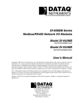
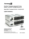
A-GPRS1081 User’s Manual Beijing ART Technology Development Co., Ltd A-GPRS1081 User’s Manual Version : v6.220 Contents CONTENTS...........................................................................................................................................................................2 CHAPTER 1 INTRODUCTION ............................................................................................................................................3 1.1 Overview.....................................................................................................................................................................3 1.2 Features .......................................................................................................................................................................3 1.3 Check List ...................................................................................................................................................................4 1.4 Installation Guide........................................................................................................................................................4 CHAPTER 2 HARDWARE INSTRUCTION..........................................................................................................................5 2.1 Terminal Distribution ..................................................................................................................................................5 2.2 Analog Input................................................................................................................................................................6 2.3 Analog Output.............................................................................................................................................................6 2.4 Digital Input ................................................................................................................................................................7 2.5 Digital Output .............................................................................................................................................................7 2.6 Serial Communication.................................................................................................................................................8 2.7 DIP switch...................................................................................................................................................................8 2.8 Power Supply ..............................................................................................................................................................9 2.9 Status lights .................................................................................................................................................................9 2.10 Potentiometer ............................................................................................................................................................9 CHAPTER 3 PARAMETER CONFIGURATION ................................................................................................................10 Local COM port configuration mode..........................................................................................................................10 GPRS-Config.exe configuration program...............................................................................................................10 2.1.1 GPRS-Config.exe Configuration Program.....................................................................................................10 2.1.2 AT Parameter Configuration Protocol ............................................................................................................11 2.3 Message Configuration .............................................................................................................................................13 CHAPTER 4 FUNCTION SETTINGS DESCRIPTION ......................................................................................................14 CHAPTER 5 SERVER PROGRAM .....................................................................................................................................17 CHAPTER 6 NOTES AND WARRANTY POLICY...............................................................................................................18 6.1 Notes .........................................................................................................................................................................18 6.2 Warranty Policy.........................................................................................................................................................18 2 Beijing ART Technology Development Co., Ltd. Chapter 1 Introduction 1.1 Overview A-GPRS1081 is wireless data transmission terminal device which based on GPRS, supplies AI, AO, DI, DO, it can realize long-distance communication, wireless communication and Network communication. Operating System Support The operational under most popular operating systems such as windowsxp/2000/2003/Vista etc. however, ART device drivers provide easier installation, configuration and better performance for windowsXP, windows2000/2003, Vista, Please refer to the respective operating system's manual for how to install and configure the standard driver. Wide applications A-GPRS1081 module has a wide range of applications, following are some typical applications: 1 Power Down Automatically Meter System 2 Environment Monitoring Systems 3 Urban Street Lamps Lighting System 4 Industrial Automation Control Systems 5 Financial Control Systems 6 Mine Control System 7 Oil Control Systems 1.2 Features 8-channel 16-bit differential isolated analog input (±10V) 2-channel 12-bit isolated analog output (0~5V/0~10V) 8-channel isolated digital input 8-channel relay output(30VDC@2A) Support data centers Support data center dynamic domain name or IP address access Support three working mode: on-line forever, idle offline, and idle power-off Support the automatic re-connection function Support local and remote graphical interface for configuration and the maintenance With power source, connection status, and the operation indicator light; Support local and remote firmware upgrade Supply RS-232/485 COM port Reliable design of multiple hardware and software, and build-in the watchdog 3 A-GPRS1081 User’s Manual Version : v6.220 Supply single voltage from +7V ~ +26V (Recommended +9V ~ +12V) Operating Temperature: -20℃ ~ +70℃ Operate humidity: 90%; A-GPRS1081’s diagram is as follow: 1.3 Check List Unpack the A-GPRS1081 series package, you should find the following items: 1 A-GPRS1081 data transmission module; 2 Device driver diskettes: a) Driver; b) User's manual (this manual). 3 One serial port cable. 4 One Power Supply. 1.4 Installation Guide Methods about how to install A-GPRS1081 in different operating systems are the same, our company provides a CD-ROM that contains the installation program “Setup.exe’’, and users double-click the installation program, then through the prompting of the interface to complete the installation. 4 Beijing ART Technology Development Co., Ltd. Chapter 2 Hardware Instruction 2.1 Terminal Distribution Terminal Distribution picture is shown as following (figure 2.1): Figure 2.1 5 A-GPRS1081 User’s Manual Version : v6.220 2.2 Analog Input A-GPRS1081 is differential isolated analog input, input range: ±10V. The specific connection method in Figure2.2: IN7IN7+ IN6IN6+ IN5IN5+ IN4IN4+ IN3IN3+ IN2IN2+ IN1IN1+ IN0IN0+ Figure2.2 Note: first, we should give the power to A-GPRS1081, and then give analog input signal in order to ensure the effective collection. 2.3 Analog Output A-GPRS1081 has 2-channel 12-bit analog output。 Connection method in Figure 2.3 VOUT1 Load VOUT0 Load AGND Figure 2.3 6 Beijing ART Technology Development Co., Ltd. 2.4 Digital Input A-GPRS1081 has 8-channel isolated digital input,Connection method in Figures. IN.GND IN.COM IN.GND + _ DI0 IN.COM DI1 DI0 DI2 DI1 DI3 DI2 DI4 DI3 DI5 DI4 DI6 DI5 DI7 DI6 DI7 Figure2.4-1 dry input connection Figure2.4-2 wet input connection. 2.5 Digital Output A-GPRS1081 digital output is relay mode. Connection method is shown in Figure2.5. K0+ Load K0K1+ Load K1K2+ K2K3+ K3K4+ K4K5+ K5K6+ Load K6K7+ Load K7Figure 2.5 7 A-GPRS1081 User’s Manual Version : v6.220 2.6 Serial Communication A-GPRS1081 supplies one DB9 male connector, which is 5-wire serial. 9 CTS 8 RTS 7 6 5 GND 4 3 TXD 2 RXD 1 Figure 2.6 A-GPRS1081 also supplies RS485 communication interface. 2.7 DIP switch S2 ON DIP switch S2 on the A-GPRS1081, is used to switch serial connections. When DIP switch is allocated to "ON", it stands for "1", allocated to another side stands for "0." When you select RS485 mode, the 1 and 2 DIP switches are allocated to "ON", the 3 and 4 are allocated to the other side, schematic as follows: ON 1 2 3 4 S2 ON When select RS232mode,the 3and 4 DIP switches are allocated to "ON", the 1 and 2 are allocated to the other side, schematic as follows: ON 1 2 3 4 8 Beijing ART Technology Development Co., Ltd. 2.8 Power Supply Power supply connection method shown in Figure2.7, PWRIN connects with GND in order to supply power. Figure 2.7 2.9 Status lights NET DATA GPRS PWR A-GPRS1081 is equipped with four LED indicator lights: PWR (Power LED), DATA (communications lamp), NET (network status lights) and GPRS (GPRS status lights). PWR: Power indicator light, on for normal. DATA: communications indicator. NET: Network Status lights, blinking stands for network status. GPRS: GPRS status lights, after electricity, if it lighting all the time, it stands for GPRS network existence. The indicator as follows: 2.10 Potentiometer A-GPRS1081 has five regulatory potentiometers(RP1, RP2, RP3, RP4 and RP5), Their regulatory functions are as follows: RP1: DA analog output full-scale adjustment RP2: VOUT1 analog output zero adjustment RP3: VOUT0 analog output zero adjustment RP4: VOUT1 analog output full-scale adjustment RP5: VOUT0 analog output full-scale adjustment 9 A-GPRS1081 User’s Manual Version : v6.220 Chapter 3 Parameter Configuration We have three ways to configure parameters of A-GPRS1081: these are local COM port configuration, long-distance configuration and message configuration. Local COM port configuration mode Local COM port configuration uses A-GPRS_Config.exe or AT command. Figure 3.1.1 Schematic diagram of the local serial port configuration There are two ways can enter to the local configuration mode, show as follows. When DTU power-on: when give the power to DTU, it will check whether there is space in the serial port, if there is space, that the user requested access to the configuration mode. Therefore, we only need to send space to serial port continuously before give the power to DTU (baud rate 115200, 8-bit data bit, 1 stop bit, noparity), and then give the power to DTU, you can enter the local serial port configuration mode. Note: If it receives character “e” when give the power to DTU, it will rest DTU; if it receives character “a”, we can do AT mandate for SIM300. 2 When DTU normal working: when DTU is in a normal communication status, we can send characters in table 2.1 to DTU through serial port to make DTU exit present work mode, and then enter the configuration mode. Table2.1 Pre-idle time Character Idle interval time Least 100ms +++ is set \r\n Least 100ms GPRS-Config.exe configuration program 2.1.1 GPRS-Config.exe Configuration Program The methord of A-GPRS1081 enters to the configuration mode: (first do not give the power to module) 10 Beijing ART Technology Development Co., Ltd. 1 Connect the COM port with the module. 2 Click the “enter configuration status” button, and then give power to A-GPRS1081 quickly. (Show as the following) 3 Click the “get information” button, then we can read the information of module, or we can wait for seconds because it can get information automatically. 4 In the left of user interface, there is a “local COM port configuration” tool, we can change the information in it, when it has been changed, we can save new information by clicking the “save configuration” button. 2.1.2 AT Parameter Configuration Protocol After DTU into the configuration mode, accordingly we can send command frames with configuration message, by command frames we can read or write parameters. Command frames all use ASCII characters. This not only gives the user convenient to use hyper terminal for parameter configuration in absence of configuration tool, but also allows users to write the DTU configuration program in their own device easily. Command frame structures are shown in Table Table2.2. There are two types of command, write commands and read commands. Write commands are used to configuration parameters, read commands are used to query the current configuration. The difference between them is that read commands are not with configuration parameters and characters after the command are different. Write commands "=" said the assignment. Read command "?" said the question. 11 A-GPRS1081 User’s Manual Version : v6.220 Command codes are different because the configuration objects are different, but these codes must comply with requirements of regulations (show as Table 2.3). If use other command codes, DTU will return “ERR CMD”, for another way, if write command with parameter configuration is not illegality (for example the baud rate has surpassed the scope of requirement), then DTU will refuse to receive this parameter and return “ERR DATA”. Note: 1 The data in command frame is all ASCII characters, and all inputted characters do not be divided the big or small letter; 2 Command codes can be found in Table 2.3 3 Writing command frames’ length can be found in Table2.3 Table 2.2 Command Frame Type Format Writing Command AT+ command code=parameter Writing Respon se Right OK\r\n Command mistake ERR CMD\r\n Parameter mistake ERR DATA\r\n Reading command AT+ Command Code?\r\n Reading Response Command code =Parameter\r\n Table2.3 Maximum Function name type code Settings length Local Setting Target Setting Module type R DTUTYPE 10 Such as ART1081 Device ID R DTUID 15 unique ID,can not change Device software version R SWVER 5 Such as V1.00 Device name RW DTUNAM 15 Such as ARTDTU01 SIM card number RW PHON 11 Such as 15810437433 Work Mode RW MODE 1 Data Center Number RW SVRCNT 1 1~2 DNS1 RW DNS1IP 15 Such as 202.106.0.20 DNS2 RW DNS2IP 15 Such as 211.136.17.107 Main data center IP RW SVRIP 15 Such as221.218.157.55 Main data center domain name RW SVRNAM 40 Such as’www.sohu.com’ Main data center port No. RW SVRPORT 5 Such as 80 Main data center link mode RW SVRMODE 1 0: TCP connection 12 0:onlineforever1:idle winding2:idlepower-down Beijing ART Technology Development Co., Ltd. 1: UDP connection Transfer Control Network Parameters Control Command Standby data center IP RW SVR1IP 15 Such as 192.168.0.1 Standby data center domain name RW SVR1NAM 40 Such as “www.163.com” Standby data center port No. RW SVR1PORT 5 Standby data center link mode RW SVR1MOD E 1 The number of reconnection RW TRYCNT 2 1~99 The number of reconnection interval RW TRYTIM 5 10~65534s COM Baud Rate RW SERBAUD 6 300~115200 COM Data Bit length RW SERDAT 1 5~8 COM Stop Bit length RW SERSTP 1 1~2 COM Parity type RW SERCHK 4 Heartbeat Packet Interval(s) RW BEATTIM 5 30~65534s Heartbeat Packet Timeout(s) RW BEATOUT 5 30~65534s Idle linetime RW IDLETIM 5 30~65534ms Whether local port access RW ISLOCAL 1 0:GPRS 1:local port Local device ID RW MTU 4 1~1024 byte APN RW APN 20 Default empty APN User name RW USRNAM 20 Default empty APN password RW PWD 20 Default empty SMS Center Number RW SMSNO 14 Default empty SMS Certification User 1 RW USERNO1 14 SMS Certification User 2 RW USERNO2 14 SMS Certification User 3 RW USERNO3 14 Module Password RW DTUPWD 6 ON:putout Debugging information output RW DBGINF 3 ON:putout Such as 80 0: TCP connection 1: UDP connection 2.3 Message Configuration SMS configuration is a mobile phone, enter commands to configure, but please note: Note: One message only can send one command, format is: 6 passwords +":"+ command (without the prefix "AT +"). All characters are Western. Not only the telephone number is the same as certification number, but also the passwords have been passed, then SMS configuration can work. SMS wake-up command "WAKEUP". SMS Configuration Support Telephone wake-up: telephone call’s time must over two rings , and was hung up after the wake-up. 13 A-GPRS1081 User’s Manual Version : v6.220 Chapter 4 Function Settings Description Export Configuration Save the modified configuration items. Import Configuration Load the configuration items previously saved. Reset DTU Module Software reset actions will be executed. Restore Factory Settings Restore module to factory settings in case of configuration confusion. SWVER Software version. DTUNAM DTU device name, be used to distinguished different devices when multiple modules are being used. DTUNAM limited to 15 characters. SIM Card Number (PHON) Mobile phone number, 11 ASCII characters, such as "15810437433". MODE There are three modes for A-GPRS1081:“Always online”, “idle offline”, “idle power down”. Always online: It will connect to the preconfigured server when power on the module. And it will be kept online all the time so the data can be transmitted at any time. idle offline: It will connect to the preconfigured server when power on the module. The module will disconnect and turns to the sleeping mode if there isn’t any data in a period of time. There are three methods to enable re-establish connection between the module and the server. Send data to the serial port of the module, the module will connect to the server and then send the out. . Telephone wake-up: call the SIM card number, hang up after it rings for two times, the module will re-establish a connection with the server SMS wake-up: set one of the SMS certification users to the SIM card number in the Configuration Tool. The format of the number is “+861**********”. (for China’s SIM card, it is 86) Send the SMS “888888: Wakeup”. It will return “OK” which means the module has re-connected to the serve. idle power down: after the module disconnecting the connection with the server, the module will cut off the power of GPRS module, and make the system into power-down status to achieve low power consumption There is only one method to wake up the module: send data to the serial port of the module, the module will connect to the server after the data is sent successfully. 14 Beijing ART Technology Development Co., Ltd. DTUMODE This parameter is used to set the module's functionality mode, "CLIENT" or "SERVER". For “CLIENT” mode, the module connects the data center server as a client. For “SERVER” mode, the module waits for the connection from the client as a server. When use the point to point function, configure one module “CLIENT”, and the other “SERVER”. SVRIP, SVRNAM, SVRPORT, CNTMODE (the parameters of the main center server) A target server configuration includes IP address and port number, if the server does not have a fixed IP address, you can use the domain name. When the server IP address is validity, the domain name will be ignored. In communication network, it has TCP and UDP communication. SVR1IP1, SVR1NAM1, SVR1PORT1, CNTMODE1 (the parameters of the secondary center server) A target server configuration includes IP address and port number, if the server does not have a fixed IP address, you can use the domain name. When the server's IP address validity, the domain name will be ignored. In the several attempts to connect the main central server fails, the module will automatically switch to connect alternate central server. When using the standby server, if it suddenly disconnected during the remote configuration, the module will re-connect standby server. If it suddenly disconnected in operating mode, the target server will switch back to the main central server. TRYCNT, TRYTIM, TRYSPAC The number of target re-connection, used to control the number of the same goal connection of the connection with batch. “0” stands for regardless of batch. The interval of target connection is used to control the time between two connections, the smallest time is 10s, and the longest time is 65.5536s. The interruption interval of target connection is used to control the time of two groups’ connections, the smallest is 1 minute, and the longest is 65,534 minutes. SERBAUD Serial baud-rates. Table4.1 Supported baud-rates Standard baud-rate 300 600 1200 2400 4800 9600 19200 38400 57600 115200 SERDAT, SERSTP Serial data bit (stop bit) length. SERCHK Check type of serial. Table4.2 relationship between values and checking types Baud-rate Set value No checking Odd checking Even checking NON ODD EVEN Compulsory to 1 1 BEATTIM Users can set heartbeat packet interval time, the range is 30 ~ 65534 (unit: seconds). BEATDATA 15 Compulsory to 0 0 A-GPRS1081 User’s Manual Version : v6.220 User can manually set the heartbeat data, such as: "0x3F", using the AT command configuration, format: "AT + BEATDAT = 3F". SERS, MTU Frame interval of time and the maximum length of data packets IDLETIM Idle time of downline. APN, USRNAM, PWD APN name, user name, and password. LCOPORT Local port number. DTUPWD Login Password. DBGINF This parameter controls whether the data input is "echo" and whether there are "debug information" outputs. 16 Beijing ART Technology Development Co., Ltd. Chapter 5 Server program Application framework Show as figure: Note: Default listening port is 5000; the server program only has one monitor port, allow 1000 clients to establish connection at the same time. It can read the AD, DI, DO, DA manually, but also can be read through the timer. Workflow: 1 Input port number in the port number edit box, click "Start" . 2 If there is client connection, then you can visit the module. 3 We can select different functions through "Function box" . 4 It can read timing module data 17 . A-GPRS1081 User’s Manual Version : v6.220 Chapter 6 Notes and Warranty Policy 6.1 Notes In our products’ packing, user can find a user manual, a A-GPRS1081 module and a quality guarantee card. Users must keep quality guarantee card carefully, if the products have some problems and need repairing, please send products together with quality guarantee card to ART, we will provide good after-sale service and solve the problem as quickly as we can. When using A-GPRS1081, in order to prevent the IC (chip) from electrostatic harm, please do not touch IC (chip) in the front panel of A-GPRS1081 module. 6.2 Warranty Policy Thank you for choosing ART. To understand your rights and enjoy all the after-sales services we offer, please read the following carefully. 1. Before using ART’s products please read the user manual and follow the instructions exactly. When sending in damaged products for repair, please attach an RMA application form which can be downloaded from: www.art-control.com. 2. All ART products come with a limited two-year warranty: ¾ The warranty period starts on the day the product is shipped from ART’s factory ¾ For products containing storage devices (hard drives, flash cards, etc.), please back up your data before sending them for repair. ART is not responsible for any loss of data. ¾ Please ensure the use of properly licensed software with our systems. ART does not condone the use of pirated software and will not service systems using such software. ART will not be held legally responsible for products shipped with unlicensed software installed by the user. 3. Our repair service is not covered by ART's guarantee in the following situations: ¾ Damage caused by not following instructions in the User's Manual. ¾ Damage caused by carelessness on the user's part during product transportation. ¾ Damage caused by unsuitable storage environments (i.e. high temperatures, high humidity, or volatile chemicals). ¾ Damage from improper repair by unauthorized ART technicians. ¾ Products with altered and/or damaged serial numbers are not entitled to our service. 4. Customers are responsible for shipping costs to transport damaged products to our company or sales office. 5. To ensure the speed and quality of product repair, please download an RMA application form from our company website. 18