1
HYDRO POWER UNIT 3
Installation and Operation Manual
Intended for specialized personnel or expert users
Please read these instructions carefully before installing, servicing, or operating the equipment.
This manual may be modified without notice. See: www.harken.com/manuals for updated versions.
PLEASE SAVE THESE INSTRUCTIONS
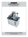
The Hydro Power Unit pictured above is for display purposes only. Actual system purchased may vary.
Table of Contents
INTRODUCTION............................................................................................................................................... 3
UNIT SELECTION AND PARTS LIST....................................................................................................................... 4
SAFETY INFORMATION................................................................................................................................. 5 - 6
POWER UNIT INSTALLATION.......................................................................................................................... 7 - 8
Planning installation
.
Location in boat
Secure power unit
Mount control box
HYDRAULIC INSTALLATION.......................................................................................................................... 9 - 11
Hose and fitting selection recommendation
Hose shortening
End fittings
Fitting instructions
Port identification
Configuration
Function assignment
Manifold blanking plates
Flushing hoses
Connecting hoses
Case drains
Mounting clamp hose support
Protect hoses from sunlight
Individual function protection
ELECTRICAL INSTALLATION........................................................................................................................ 12 - 14
Wire selection
.
Connect deck switches to ECB
Connect ECB to power supply
Connect HPU motor and valves to ECB
Connect HPU to battery
COMMISSIONING...................................................................................................................................... 15 - 16
Fill reservoir
.
Hydraulic fluid
Closed circuit
Leak check
One-way function flush
System validation
Function pressure check
Oil level and filter
OPERATION...................................................................................................................................................17
Power up / power down
Oil level
Motor thermal protection
Single and multiple function operation
Filter element replacement schedule
Hydraulic oil change schedule
MAINTENANCE........................................................................................................................................ 18 - 19
How to change oil
Leakage inspection
Cleanliness inspection
Oil level inspection
Additional maintenance points
TROUBLESHOOTING........................................................................................................................................19
DRAWINGS AND SCHEMATICS.....................................................................................................................20 - 31
Bill of Materials; Exploded View Diagram; 3D Rendering; Electrical Schematics; Motor Thermal Relay Schematic;
Suggested Wiring Schematics; Control Box Mounting Dimensions; Control Box Interior Diagram
WARRANTY.......................................................................................................................................Back Cover
2
Hydro 3
Introduction
HARKEN Hydraulic Power Units (HPU) are the complete power solution. Offered in three sizes (Hydro 1, 2 and 3), the HPU can power
functions including winches, furlers, sail trim cylinders, windlasses and keel cylinders. HPUs can include waterproof, prewired electronic
control boxes (ECB) or act as stand–alone, central or supplemental power units.
HARKEN HPU features a 4kW 24VDC motor which is sized alongside the pump to power a single function. With additional pumps and
motors, multiple functions can run simultaneously, or the built-in double-flow feature can supply more oil to power-intensive functions.
Motors are fan-cooled, series-wound and energy-efficient at all speeds.
Factory-installed manifolds and pumps are internally plumbed, saving space, installation time and additional hardware. Valve manifolds
are equipped with horizontal ports to provide ease with hose routing. Elevated reservoir fill cap keeps oil from spilling, filters air
exchange and removes moisture from the tank to ensure a healthy hydraulic power unit. Drop-in return line filters with status gauge
make maintenance fast and easy.
The prewired ECB features sealed passage for switch and valve wires. The ECB is prewired internally and contacts are labeled. The user
is required to make electrical connections for supply power, switches and valves.
Tank-mounted, electrical motor
contactors meet the IP67
waterproof specification.
Use the built-in, double-flow
function to supply more oil to
power-intensive equipment.
Fan-cooled, series-wound
motors are energyefficient at all speeds.
Drop-in return line filters with
status gauges provide a no-mess
alternative to typical spin-on styles.
Plumbing to manifolds is
under reservoir top so there
is no exposed plumbing
(not visable).
Hydro 3 (HPU)
Coated aluminum tanks have hardcoatanodized 6061-T6 aluminum top plates.
Manifolds are made with clear-anodized
aluminum.
External shut-off switches.
Sealable penetrations into
control box provided for
deck switch wiring.
Deutsch receptacle and plug
connects motor power cables
to electronic control box
Prewired and waterproofed
control boxes are molded
from extremely tough
polycarbonate.
Manifolds and pumps are
preplumbed, saving space,
installation time, and
additional hardware.
Electronic
Control Box (ECB)
Remote Manifold
Hydro 3
3
Power Unit Selection / Parts
Power Unit Selection
Power unit selection must be based on the flow and pressure requirements for all hydraulic equipment that will operate at the same time.
Most HARKEN hydraulic equipment (winches, furlers, etc.) requires a flow of 4GPM/15 LPM, with a maximum operating pressure of
2000 PSI/140 BAR.
To select the correct power unit:
1. Consult the manual for each piece of hydraulic equipment that will be driven by the power unit. Note flow and pressure.
2. Determine which pieces of hydraulic equipment or circuits will be used at the same time (i.e. winch and furler).
3. Compare total flow/pressure required for each piece to table below to select power unit.
HARKEN Hydro Power Units are available in three sizes: Hydro 1, 2 and 3. Each motor/pump combination is rated at 4 GPM/15 LPM with
a maximum operating pressure of 2000 PSI/140 BAR.
Hydraulic Power Units
Tank
capacity
gal
l
Maximum
continuous output
psi@gpm bar@l/m
210
7.9
30
2000 @ 4
140 @ 15
89
2 x 4000 Watt
2 x 210
18.5
70
2000 @ 8
140 @ 30
3 x 4000 Watt
3 x 210
18.5
70 2000 @ 12 140 @ 45
Power
unit
Number of
functions
Max
simultaneous
functions
24v DC
Motor
Maximum
current draw
(amps)
Hydro 1
4
1
1 x 4000 Watt
Hydro 2
9*
2**
Hydro 3
15*
3**
Without manifolds
lb
kg
Weight
With attached manifolds
lb
kg
40.5
102
182
82.6
233
105.9
M10
194
88.2
M10
246
111.4
M10
*One function delivers double flow output (8 gpm) using 2 motors **This number is reduced by one when a double flow function is in use.
Wiring to Connect Valves to Electronic Control Box
(1 Cable per Valve)
Hydraulic Power
Unit (HPU)
You must Supply
Suitable Hydraulic Hoses (See pg. 9)
Switches
Electronic Control
Box (ECB)
Battery Cable with Suitable Fuses
HPU Mounting Bolts – Four (4) M10
Depth of Threaded Holes in Tank Bottom – 15 mm
Included with Unit
ECB Mounting Bolts – Four (4) M6 or 1/4"
1. Hydraulic Power Unit (HPU)
2. Electronic Control Box (ECB)
3. Electric Wiring Cables with Terminals
2 Cables per motor to connect power unit motor to ECB
1 Cable per valve to connect power unit to ECB
4. Remote Manifold
Mounting Pad to Secure Power Unit to Boat (See pg. 8)
4
Hydraulic Oil (See pg. 15)
Flow Control Valves If Required (See pg. 9)
Pressure Reducing Valves If Required (See pg. 9)
Pressure Relief Valves If Required (See pg. 9)
Hydro 3
Fasteners
46.1
Safety
Important Safety Information
Read all instructions carefully and follow all safety precautions to avoid personal injury or property damage during system operation.
Harken is not responsible for damage or injury resulting from unsafe product use, lack of maintenance or incorrect product and/or
system operation. Contact Harken with questions regarding safety precautions and operations. If you lack training on hydraulic safety,
consult a hydraulic distribution or service center for a hydraulic safety course. Failure to comply with the following cautions and
warnings could result in equipment damage and personal injury.
Symbols and Safety Statements Used in this Manual
Symbols and safety statements have been placed throughout this text to call attention to special information that may affect the
equipment and/or the equipment operator. Following is an explanation for your reference.
DANGER! This symbol alerts you to hazards that cause death or serious injury.
WARNING! This symbol alerts you to potential hazards that may kill or hurt you and others
if you don't follow instructions.
CAUTION! This symbol alerts you to potential hazards that may damage equipment or void
product warranty.
IMPORTANT! Identifies condition or task requiring special attention.
Hydro 3
5
Safety
Safety Requirements
The instructions provided with this manual are for installation and use only. The HARKEN Power Unit must only be serviced by
a qualified hydraulic technician. For repair service, contact HARKEN to find the repair site nearest you.
WARNING! Strictly follow all instructions to avoid an accident, damage to your vessel, personal injury or death.
See www.harken.com/manuals for additional safety information.
• Always wear eye protection.
• Make sure all components are rated for the maximum system pressure. Hose and fittings generally have a 4:1 safety factor.
In static applications, these safety factors are normally reduced to 2:1. Special care should be used in selecting the proper
products for these systems. There is a correlation between cost of components and their quality.
• Do not exceed equipment ratings. Overloading causes equipment failure and possible personal injury.
• Never set the relief valve pressure higher than the maximum rated pump pressure. Doing so may result in equipment damage
and/or personal injury.
• System operating pressure must not exceed the pressure rating of the lowest rated component in the system. If in question,
install pressure gauges in the system to monitor operating pressure. They are your window to what is happening in the system.
• Keep hydraulic equipment away from flames and heat. Excessive heat will soften packings and seals, resulting in oil leaks.
Heat also weakens hose materials and packings. For optimum performance, do not expose equipment to temperatures of
65°C [150°F] or higher.
• Use caution when searching for leaks, cracks, kinks or other damage. Serious injury can occur to hands or face from
pressure build-up or heated fluids.
• Do not handle pressurized hoses. Escaping oil under pressure can penetrate the skin, causing serious injury. If oil is
injected under the skin, seek immediate medical attention.
• Relieve system pressure before servicing or replacing hose lines.
• Never remove a hose line from a pressurized motor or cylinder.
• Avoid hydraulic hose damage. Avoid sharp bends and kinks when routing hydraulic hoses. Using a bent or kinked hose
will cause severe back-pressure. Sharp bends and kinks will internally damage the hose leading to premature hose failure.
• Route hose assemblies so that all bends are directed away from the operator.
• Do not drop heavy objects on hose. A sharp impact may cause internal damage to hose wire strands.
• Applying pressure to a damaged hose may cause it to rupture.
• Do not lift hydraulic equipment by the hoses or swivel couplers. Use the carrying handle or other means of safe transport.
6
Hydro 3
Installation
While unpacking the hydraulic power unit (HPU) and electronic control box (ECB), inspect for irregularities. During transport the power
unit may have been exposed to many unusual conditions. If irregularities appear, document details and contact shipper and HARKEN
distributor.
Plan Installation
Mounting is required for both the HPU and the ECB. Because this installation is on a boat, the following are some points to consider
when choosing the installation location:
Location in Boat
Filter status indicator
• Dry and well-ventilated, typically near the engine room.
• HPU and ECB to be mounted within close mutual
proximity, recommended maximum 5 m wire run.
(See Electrical Installation, pg. 12)
• Provide necessary clearance for HPU.
• HPU in close proximity to battery and power supply
to reduce voltage drop. (See Electrical Installation,
pg. 12)
• Provide access for maintenance and servicing. Make
access available to filler tube, filter, filter status
indicator and site gauge.
• Central to the system as illustrated in “ Typical System”
diagram.
Case Drain Port
Filler tube
• Provide routing for hydraulic hoses from HPU to
functions. Hoses attach to manifold horizontally.
• Nearest boat’s centerline in an upright position to
reduce the heeling extremes.
Attached manifold
Choose an area close to the plumbing center of the system.
Typical System
Electronic Control
Box (ECB)
Hydraulic Power Unit
(HPU)
Hydro 3
7
Installation
Securing Hydraulic Power Unit
CAUTION! The HPU was shipped cleaned and tested. HARKEN strongly recommends against disassembly or removal
of the tank lid or the HPU components. Introduction of contaminants can cause operational problems and possibly
void warranty.
A mounting pad with tie downs will be required for securing the HPU to
the boat. Every installation is unique. Considerations for the mounting
pad and tie downs follow:
•
The mounting pad (not supplied) may be a tray, platform
or bridge that securely attaches to the boat and supports
the HPU. Consider total weight and overall dimensions.
(See Technical Data, pg. 20).
• The HPU is fastened using four (4) M10 – 1.5 x 15 mm bolts
which thread into the underside of the HPU tank. Underside
access must be available for fastening.
• Additional tie down supports (not supplied) are required.
These may be similar to battery box tie downs and fabricated
from nylon or polyester webbing. Tie downs should attach
to the mounting pad and be lashed over the HPU tank as
illustrated.
2"
(50 mm)
Approximate clearance
required for installation
8"
(200 mm)
4"
(100 mm)
Mount Control Box
4"
(100 mm)
Choose a suitable location for the electronic control box (ECB) as described in the planning section.
The ECB is (L) 16.75" (425 mm)x (W) 12" (305 mm) x (H) 6.7" (169 mm) and is externally mounted using four (4) M6 (¼") fasteners.
The ECB is water resistant to IP67; however, its location should be dry and within a 5 m wire run to the HPU. Power supply cables
and deck switches connect to ECB. (See Electrical Installation, pg. 13).
CAUTION! Cleanliness is crucial for any hydraulic system. Contamination is the primary cause of seal failure. Most
hydraulic hoses contain manufacturing debris when purchased. Attaching a dirty hose will contaminate the system.
Always flush hoses thoroughly before use. Failure to do so may void warranty.
Measure Hose Run
Measure hydraulic hose runs after the HPU has been mounted.
Remember these important points when measuring runs:
• Short straight runs between HPU and function are best.
• Avoid sharp edges which may chafe the hose.
• Minimize fittings/connections throughout the run to avoid
possible leak points.
• Minimize 90° bends, which increase system losses and
decrease performance. If unavoidable use a 90° swept
fitting, do not use a 90° elbow fitting.
Use a swept hose fitting for a 90° bend
CAUTION! Do not exceed the manufacturer specified minimum bend radius.
8
Hydro 3
Avoid using an elbow
Hydraulic Installation
Hose and Fitting Selection Recommendation
Functions must be connected to the HPU manifold using proper
hydraulic hose size and type. Required hose type is SAE 100 R2
or SAE 100 R8. Hose size is determined by flow and run length
between HPU and function.
When ordering, specify that all hoses are flushed, filled with clean
oil and capped at point of purchase. In most conditions, HARKEN
recommends ISO 46 grade oil*. (See Oil Equivalent Table, pg. 15)
If hoses are shipped, they may not contain oil. HARKEN can
supply flushed, clean, empty hoses if ordered when purchased.
*exception noted in Hydraulic Oil section, pg. 15.
Recommended Hose ID for Hose Lengths Under 40' (12 m)
gpm
lpm
in
mm
6.3
10
12.5
10
12.5
12.5
16
16
19
1/4
3/8
Single Flow Case Drain
Double Flow Case Drain
Triple Flow Case Drain
Single Pump/Motor Function
4
15
Double Pump/Motor Function
8
30
Triple Pump/Motor Function
12
45
Supply
Return
Supply
Return
Supply
Return
1/2
3/8
1/2
1/2
5/8
5/8
3/4
IMPORTANT! Always ensure pressure rating for selected hose is equal to or greater than 2000 psi/140 bar.
Hose Shortening
Hydraulic hoses typically shorten 2% to 4% of total length when pressurized. When routing and measuring hose lines, ensure extra hose
length is added to compensate for the hose shortening under pressure.
End Fittings
Hydraulic fittings vary widely. HPU manifold A and B ports are -8 SAE female. P and T ports are -10 SAE female. The case drain is
-8 JIC male. Hose end fittings may be selected to fit existing function fittings, or function fitting may be replaced. Refer to individual
function manuals for specific A&B and drain port sizes.
Fitting Instructions
End fittings must be installed using proper tools by qualified persons. Fittings should be stainless steel whenever possible.
CAUTION! Cadmium plated fittings rust in saltwater environment. Replacement costs outweigh initial cost advantages.
Port Indentification
Hydro 3: HPU has two (2) attached manifolds, each with four (4) valve ports. It also comes with a remote manifold containing up to
four (4) valve ports. HPU remote manifold attaches via hose to pressure ports on distribution manifold.
T3 Back
Tank Ports
T2
T1
Pressure Ports
P1A
P2A
P3A
Distribution manifold
Remote manifold
Attached manifold on Hydro 3 HPU
Hydro 3
9
Hydraulic Installation
Configuration
The stock configuration of Hydro 3 is internally plumbed such that valves are pre-assigned to a manifold and motor. This is illustrated
in the Function Assignment Table. Hydro 3 unit uses valves 1-4 with manifold 1 and motor 1and valves 6-9 with manifold 2 and motor 2.
Valves 10-13 correspond with remote manifold and motor 3. Valve Station 5 is located on the distribution manifold and is used with motors
1, 2 and 3. Valve Stations 14 and 15 can be used with remote manifolds when more multiflow valves are needed.
Function Assignment
The Hydro 3 unit is equipped with two (2) attached manifolds and one (1) remote manifold per design specification. Each manifold
style has up to four (4) valve stations corresponding with four (4) ECB switches. Assign each function to its own set of valve ports.
Record the function name in the Function Assignment Table below. When assigning valves to functions, be sure to separate functions
that will run simultaneously to different manifolds. Example 1: Run primary winches on different manifold than mainsheet.
Example 2: Run primary winches on different manifold than headsail furler. Refer to this information when connecting the electric
switches. For easy reference, label the hydraulic hoses in accordance with the valve. For example: label Valve Station 1 hoses for
your attached manifold "VS1A and VS1B".
Function Assignment Table
Function
Name
10
Valve
Station Number
Attached
Manifold Number
Remote
Manifold Number
Motor
VS1
A1
—
1
VS2
A1
—
1
VS3
A1
—
1
VS4
A1
—
1
VS5
D
—
1, 2
VS6
A2
—
2
VS7
A2
—
2
VS8
A2
—
2
VS9
A2
—
2
VS10
—
R1
3
VS11
—
R1
3
VS12
—
R1
3
VS13
—
R1
3
VS14
—
*
1, 2
VS15
—
*
1, 2, 3
VS1
—
R1
1
VS2
—
R1
1
VS3
—
R1
1
VS4
—
R1
1
VS5
—
—
1, 2
VS6
—
R2
2
VS7
—
R2
2
VS8
—
R2
2
VS9
—
R2
2
VS10
—
R3
3
VS11
—
R3
3
VS12
—
R3
3
VS13
—
R3
3
VS14
—
*
1, 2
VS15
—
*
1, 2, 3
Hydro 3
Hydraulic Installation
Manifold Blanking Plates
All manifold stations must have either blanking plates or valves. Once all functions have been assigned, attach blanking plates to
stations not in use. Tighten #10-24 bolts to 4.1 ft-lb (5.6 N-m) torque. The unit is shipped with the number of valves ordered. Additional
valves may be added if blanking plates are present.
Flushing Hoses
Flush hoses prior to connecting to HPU, if not done when purchased. Use an external filtration pump (not included) to remove all debris.
Connecting Hoses
Install hoses per predetermined route.
• If hose end fittings differ, verify mating fittings prior to running the hose.
• Remove plugs from the HPU manifold and function ports to connect A and B hoses.
To prevent filled hoses from draining, connect the lower of the two ends first. This is typically the HPU.
• Attach the other hose end at the higher connection.
• If case drain hoses are required, continue with the same procedure used on A and B hoses.
• Plug all unused A and B ports to prevent contamination.
Any unused A and B ports with a valve must be plugged with ORB plugs as well.
IMPORTANT! ORB, BSPP and JIC connections do not need PTFE tape or other sealing.
Case Drains
Function motors with drain ports must be routed to a common case drain on the HPU during the installation. T-fittings may be used
to connect multiple drain port hoses to one common hose that leads to the case drain. Line sizing should be based on maximum
flow in order to prevent flow restriction and back pressure.
Example: The 3 unit is sized to fully power either three functions or two double flow functions at a time. To allow for free flow back
to the HPU, the common case drain hose that combines flow from all drain port hoses must be up-sized.
The recommended minimum hose size for function drain ports should be ¼" inner diameter (ID).
Mounting Clamp Hose Support
Support hoses using mounting clamps to prevent chafing and premature failure. Remember to allow for 2% to 4% shortening
when pressurized.
Protect Hydraulic Hose from Sunlight
Sunlight leaches out elastomers causing the cover to weather check or develop cracks deep enough to allow moisture penetration of
reinforcement. Use protective hose covers and/or store under protective cover when not in use.
Individual Function Protection
Some equipment may require lower max flow or lower max pressure than the hydro unit can deliver. Use a flow control valve, pressure
reducing valve and/or pressure relief valve to reduce maximum flow and/or maximum pressure. These valves are not included with the
Hydro 3 unit. They should be purchased as required by the original equipment manufacturer.
Hydro 3
11
Electrical Installation
HARKEN Hydro Units include 24 volt DC motors standard. 12 VDC motors are available by special order.
Electrical installation is intended to be straight forward. For instance, connections internal to the ECB are prewired. At the time of installation
the user is only required to make the necessary connections between the switches, valves, ECB, HPU and power supply/battery.
To ease installation, the ECB terminals for switches, valves, 24V power and ground are labeled. For quick reference, terminal
and valve port labeling follows a corresponding numbering scheme. For the wires routing from switches on the deck or valves on the
manifold, waterproof integrity is maintained by passage through a sealed gland. Electrical installation is divided into five basic steps:
1. Connect the deck switches to the ECB
2. Connect a ECB to power supply
3. Connect HPU motor to the ECB
4. Connect valves to the ECB
5. Connect the HPU to the battery
IMPORTANT! Adhere to electrical standards per the National Boatbuilding Regulatory Bureau.
Caution! DO NOT connect the cable from the battery to the HPU until all of the other steps are complete.
Caution! Be extremely careful when connecting the battery cables. Short circuiting the battery connections can
damage the HPU and/or motor and possibly cause damage to the boat, a fire and/or personal injury.
Caution! Never run the HPU pump without oil. This can cause serious damage to the pump and/or motor and will void
the HPU warranty.
Wire Selection
Three types of wire cables are required for installation:
1. Wires to connect switches to the ECB.
2. Wires to connect the power supply to the ECB.
3. Wires to connect the HPU to the battery.
Minimize voltage loss on battery and power supply cables by sizing wire gauge for a length of wire. Refer to the Wire Sizing Table below
for a given length of wire.
At the HPU motor contactor, the positive terminal is an 8 mm stud, and the common ground terminal is a 10 mm stud. Install end
terminals using proper crimping tool.
Wire Sizing Table
16 ft (5 m)
12
33 ft (10 m)
49 ft (15 m)
Switch or Valve to ECB
16 AWG
1.31 mm2
14 AWG
2.08 mm2
12 AWG
3.31 mm2
Power Supply to ECB
12 AWG
3.31 mm2
10 AWG
5.26 mm2
8 AWG
8.366 mm2
Battery to HPU Motor
00 AWG
67.4 mm2
0000 AWG
108 mm2
—
—
Hydro 3
Electrical Installation
Connect Deck Switches to the ECB
Install the deck switches in a convenient location. By design, two (2) deck switches are used per function. Generally, one switch would
actuate the function motor in a forward direction and the other in the reverse. Example: for a furler, the (A) switch would furl and the (B)
would unfurl.
Follow these steps to connect deck switches to ECB:
1.Select moisture barrier gland insert.
2.Pass switch wires through gland into the ECB case.
3.Connect deck switch wires per Switch Wiring Table below.
Switch wires connect to terminal strip labeled +24 - X and SWXX.
(See photo).
Note: For wire gauge information, refer to pg. 12.
Switch Wiring Table
Valve
Switch
Wire 1
Wire 2
A
+24 -1
SW1A
1
B
+24 -1
SW1B
A
+24 -2
SW2A
2
B
+24 -2
SW2B
A
+24 -3
SW3A
3
B
+24 -3
SW3B
A
+24 -4
SW4A
4
B
+24 -4
SW4B
A
+24 -5
SW5A
5
B
+24 -5
SW5B
A
+24 -6
SW6A
6
B
+24 -6
SW6B
A
+24 -7
SW7A
7
B
+24 -7
SW7B
Note: Polarity is not an issue with 2-wire deck switches
Valve
9
10
11
12
13
14
15
Switch
A
B
A
B
A
B
A
B
A
B
A
B
A
B
Wire 1
+24 -9
+24 -9
+24 -10
+24 -10
+24 -11
+24 -11
+24 -12
+24 -12
+24 -13
+24 -13
+24 -14
+24 -14
+24 -15
+24 -15
Wire 2
SW9A
SW9B
SW10A
SW10B
SW11A
SW11B
SW12A
SW12B
SW13A
SW13B
SW14A
SW14B
SW15A
SW15B
Connect ECB to Power Supply
Follow these steps to connect power to ECB:
1.Prior to making any connection, verify internal 5A circuit breaker is in OFF position and system isolation switch on ECB cover is in OFF
position.
2.Pass power supply wires through gland into the ECB case.
3.Connect power supply positive lead to the circuit breaker terminal labeled 0CB.
4.Connect power supply common lead to any GND(–) terminal.
Hydro 3
13
Electrical Installation
Connect HPU Motor and Valves to ECB
Each valve operates using a three wire cable bundle with an M12
connector.
Note: Valve wires supplied are 5M. These can be extended with a
16-gauge wire if needed. (Refer to Wire Sizing Table, pg. 12.)
Follow these steps to connect HPU motors and valves to ECB:
1.Join mating ends of Deutsch Connector to connect the ECB
to the HPU motor.
2.Pass valve wires through gland into the ECB case.
3.Connect valve wires per Valve Wiring Table at right. Valve wire
sets connect to terminal strip labeled SWXA, SWXB and GND(–).
(See photo, pg. 13).
4.Connect valve cable to M12 connector on valve.
Valve Wiring Table
Valve
1
2
3
4
5
6
7
8
9
10
11
12
13
14
15
Black
SW1A
SW2A
SW3A
SW4A
SW5A
SW6A
SW7A
SW8A
SW9A
SW10A
SW11A
SW12A
SW13A
SW14A
SW15A
White
SW1B
SW2B
SW3B
SW4B
SW5B
SW6B
SW7B
SW8B
SW9B
SW10B
SW11B
SW12B
SW13B
SW14B
SW15B
Blue
Ground
Ground
Ground
Ground
Ground
Ground
Ground
Ground
Ground
Ground
Ground
Ground
Ground
Ground
Ground
IMPORTANT! Align key and keyway on connector.
1
2
4
3
5
Brown (Not Used)
White (N/C) Port A or B
Black (N/C) Port B or A
Blue (–)
Green/Yellow (Not Used)
Connect HPU to Battery
Follow these steps to connect HPU to Battery:
1.A 250-300A circuit breaker or fuse (not supplied) must be installed between HPU motor and battery. Prior to making connection,
remove fuse element or verify circuit break is in OFF position.
2.Connect positive lead from fuse to open 8 mm terminal stud contactor on solenoid switch.
3.Connect from fuse to battery.
4.Connect negative lead from 10 mm stud on motor case to common terminal or (-) battery terminal.
Caution! DO NOT close the circuit with the fuse or circuit breaker until the Commissioning phase.
14
Hydro 3
Commissioning
When commissioning hydraulic equipment, it is extremely important to carefully follow each procedure to avoid premature system damage
and/or failure. Secure connections, ensure cleanliness, confirm proper fluid levels and perform all recommended tests. The following are
instructions to ensure proper commissioning of your Hydro 3.
Filling Reservoir
Pump hydraulic oil through an adequate filter into reservoir. Fill until oil
level indicator is 2/3 - 3/4 full. Inspect for leaks. Reservoir capacity is 70
liters (18.5 gal.). Approximately 55 liters (14.5 gal) will be needed for the
reservoir. If installation is completed with empty hoses, extra oil will be
needed to meet the 2/3 - 3/4 tank fill indicator requirement.
Hydraulic Oil
HARKEN recommends mineral-based, ISO 46 grade oil. Refer to Oil
Equivalent Table below. If HPU is primarily used in an extreme cold
weather environment, ISO 32 is suitable.
Characteristics of good quality, mineral-based hydraulic oil are:
• Good anti-wear performance
• Resistance to oxidation depredation
• Protection against rust and corrosion
• Resistance to foaming
Oil Level
Indicator
• Ability to separate water rapidly
Filler Tube
• Suitable for widely varying temperature conditions
• Good low temperature flow properties
• Retains viscosity/temperature characteristics while in service
• Universally available
Note: If the hydraulic installation was completed with empty hoses,
be sure to have extra oil on hand to top off the tank as the
hoses are filled.
Caution! Never run the HPU pump without oil. This will void warranty.
Oil Equivalent Table
Manufacturer
Brand Name
Amoco
®
Ashland Valvoline
®
Atlantic Richfield
®
BP
Chevron® USA
Manufacturer
Brand Name
Gulf
Rykon 46
®
46AW
Evergol 46
Mobil
DTE 20 Series 25
Duro AW-S-215
Mobil
DTE 10 Series 19
®
®
Pennzol
Energol HLP
®
Phillips Petroleum® Corp.
AW Hydraulic Oil 46
Magnus A 315
Tellus 46
Citgo® Petroleum Corp.
A/W Pacemaker XD-46
Shell®
Tellus T46
Citgo® Petroleum Corp.
A/W 46
Shell®
SUNTAC WR 150 WR
Conoco (Continental)
®
Nuto H46
Exxon
Nuto H46
®
Texaco
Super Hydraulic Oil 21
Esso
®
®
Union
®
Rando HD 46
Hydraulic Oil Unax AW 215
Registered trademarks: Amoco® - Amoco Oil Company: Ashland Valvoline® - Ashland, Inc.; Atlantic Richfield® - Atlantic Richfield Co.; BP® - BP p.l.c; Chevron® USA - Chevron Intellectual
Property LLC; Citgo® Petroleum Corp. - Citgo Petroleum Corp.; Conoco® (Continental) - ConocoPhillips; Esso® and Exxon® - ExxonMobil; Gulf® - GULF Oil International; Mobil® - ExxonMobil;
Pennzoil® - SOPUS Products; Phillips Petroleum® Corp. - Phillips 66; Shell® - SOPUS Products; Texaco® - Chevron Intellectual Property LLC: Union® - Phillips 66.
Hydro 3
15
Commissioning
Closing Circuit
Verify the system installation after completing hydraulic and electrical installation and filling the reservoir. To begin closing the electrical circuit:
1.Flip internal ECB circuit breaker to ON position.
2.Install fuse element between HPU motor and battery cable or flip circuit breaker to ON position.
3.Flip system isolation switch on ECB cover to ON position.
Leak Check
To perform leak check, run one function at a time in a single direction for 5 – 10 seconds. If installation was completed with empty
hoses, increase the run time to 10 – 30 seconds. Perform the following:
1.Confirm hose run is correct by verifying operation of intended function.
2.Inspect each fitting for leakage.
Caution! If leak is present, decrease system pressure to 0 psi before tightening fittings.
3.Tighten fitting as necessary.
4.Repeat procedure for all functions.
IMPORTANT! If installation was completed with empty hoses, check the oil level indicator after each function, and add oil as
necessary
Run Time Table
One-Way Function Flush
Hose size
Run time per 10' (3 m) of Hose
Flush the function motor through the system filter by running each function in a single
direction. Run in same direction as previous step. This process helps ensure system
cleanliness by depositing any contaminates into the system filter. Refer to Run Time
Table. Total length is sum of A and B hose. Repeat procedure for all functions.
in
mm
sec
3/8
10
12.5
16
19
25
5
7.5
10
15
25
1/2
5/8
3/4
1
System Validation
Verify proper function performance and correct switch wiring by running one function at a time first in one direction and then in the other
direction.
Single direction functions, i.e. single speed winch, are operated by one deck switch. If function does not operate per specific user manual,
switch wiring may be incorrect, or A and B hoses may be reversed. If this is the case refer to the Hydraulic and Electrical Installation sections
and verify each step.
Two direction functions, i.e. furlers, two- and three-speed winches are operated by two deck switches. Each switch operates one direction.
Verify each switch operates the intended function direction. If not, either reverse switch wiring at terminal strip inside the ECB, or reverse A
and B hoses. For more specific operational instructions refer to specific function user manual.
Function Pressure Check
Refer to each function’s user manual for maximum flow, maximum pressure and function working load before operation under stated condition.
Caution! To avoid equipment damage, DO NOT exceed function’s maximum pressure or maximum flow.
DO NOT exceed the safe working load of any function.
Carefully load system and verify function operates per specific user manual. During function operation, inspect hoses for chafing or
binding. With pressure at zero, inspect fittings for leaks. Ensure proper safety precautions are practiced to avoid personal injury due
to pressurized oil.
Caution! If leak is present, decrease system pressure to 0 psi before tightening fittings.
Oil Level and Filter
Maintain an oil level of 2/3 - 3/4 full as viewed through tank fill indicator.
Most foreign particles flush into the return filters after first few hours of operation. If system was exposed at any time to possible
contamination, replace filter element.
If you have any questions, contact your HARKEN Tech Service Representative.
16
Hydro 3
Operation
Power Up / Power Down
HARKEN Hydro Power Units have system isolation switches on
the electronic control box.
During short-term, inactive periods the system isolation switch
should be in OFF position. This deactivates deck switches.
For long-term storage, in addition to placing isolation switch in
OFF position, remove the fuse or circuit breaker between HPU
motor and battery.
Oil Level
Maintain an oil level of 2/3 - 3/4 full as viewed through Oil Level
Indicator. Always inspect oil level before use. If necessary to
maintain proper level, add more filtered oil to tank.
Electronic Control
Box (ECB)
Motor Thermal Protection
HARKEN standard Hydro Power Units feature a 4kW 24VDC
series wound motor. (12VDC motor available by special order)
Motors are specified to provide years of service under standard
operating conditions.
Due to high current draw, these motors will generate excessive
amounts of heat after extended periods of operation at load.
To avoid motor damage, the motor is equipped with an
internal thermal monitor and switch.
The motor is sized to run a minimum of five (5) minutes without
tripping the thermal switch. If overheating occurs and the thermal
switch is tripped, an indicator light on ECB will illuminate. After this
occurrence, the motor requires a variable cooling period based
ambient conditions.
Oil Level
Indicator
Internal Thermal Switch Override
IMPORTANT! In case of emergency, thermal switch override is located inside the ECB. Flip toggle switch to engage override.
Once thermal switch override is engaged, motor will operate until it stalls. If thermal switch override is engaged, HPU warranty
may be voided.
Caution! Motor operation beyond temperature limits will cause damage to motor and possibly other components.
Single- and Multiple-Function Operation
The Hydro 3 is designed to operate either three single-flow functions on different manifolds or two double-flow functions at a time.
All functions are powered by either one or a combination of two motors. If additional functions are operated simultaneously, oil flow
will be divided among all functions and performance across all operating functions will decrease.
Hydro 3
17
Maintenance
HARKEN Hydraulic Power Units will provide years trouble free operation with proper, routine
maintenance. Adherence to a maintenance schedule will lengthen component life, reduce downtime,
and minimize repair costs. Typical maintenance includes regular oil changes, replacing filter elements,
oil sampling and component inspection. Under normal operating conditions, the following maintenance
schedules are suggested:
Filter Element Replacement Schedule
• Within eight (8) operating hours after the initial commissioning
• Every 500 operating hours or when Oil Filter Status Indicator signals a dirty filter
• During any complete oil change
Filter supplied with the unit is a drop-in element (HYFEH10). Ensure O-rings are fitted into ends of filter
prior to installation. Contact HARKEN for replacement elements. If using other manufacturer,
cross-reference the filter and use element rated for 10 micron or better.
Oil Filter Status Indicator
IMPORTANT! Oil filter status indicator functions only when unit is powered and when motor and pump are running. In operating
conditions with high levels of airborne particles, inspect breather at frequent intervals.
Caution! If necessary, top off oil reservoir using proper fluid type. Do not mix oil types. Refer to Oil Equivalent Table,
pg. 15. Only use filter elements capable of meeting or exceeding the oil cleanliness level requirements.
Hydraulic Oil Change Schedule
•
•
•
After first 500 operating hours
Every 1000 operating hours or biannually regardless of accumulated operating hours
Oil change interval lengths can be adjusted (longer or shorter) if results of laboratory fluid sampling and oil analysis reveal oil is
cleaner or more contaminated than expected at 1000 operating hours.
IMPORTANT! Conduct recommended oil change schedule in accordance with fluid type, aging, and oil contamination level. Oil
condition depends on moisture content and additive level. In operating conditions with high levels of airborne particles and/or
elevated thermal loads, reduce intervals between oil changes should be reduced accordingly.
How to Change Oil
Oil change intervals are recommended based on various factors such as the type of fluid, the degree of aging and the contamination of
the oil. Water content and the levels of additives are also significant factors in determining the condition of the oil. Important guidelines
to remember are:
• Follow proper procedures when changing oil. Improper cleaning procedures may contaminate hydraulic system.
• Perform oil changes in a warm operating environment.
• Drain old oil before adding new. Reservoir may be emptied via one of two methods:
1. Place basin near HPU beneath drain plug. Remove plug and let oil drain into basin until reservoir is empty.
2. Use siphon/oil pump method to pull oil up through hose in filler tube. Use a basin to collect oil.
• Once oil is drained, use lint-free rags to clean reservoir. Remove debris prior to refilling.
• Filter oil prior to filling reservoir. Never fill a reservoir through a filler breather without filtering it prior to or during the filling process.
• Take care to not introduce contaminates from the filter housing when removing filter.
Note: Always dispose of oil properly. Contact your local waste authority, and follow guidelines for recycling and/or disposal.
Caution! Filter oil prior to filling the reservoir. Cleanliness of oil directly from barrel is not sufficient for system operation.
Contact local hydraulic service company for filter carts or pre-filtered oil.
Problems occurring during oil change result from:
•
•
•
•
•
18
Use of unsuitable hydraulic oil
Use of oil which was contaminated due to faulty storage
Failure to clean reservoir
Inadequate cleanliness when filling, i.e. dirty drums or containers
Filling to improper levels
Hydro 3
Maintenance
Leakage Inspection
After commissioning visually inspect system for leaks. Perform visual leak inspection at regular intervals. It is good practice to visually
inspect for leaks prior to every use.
Caution! If leak is present, decrease system pressure to 0 psi before tightening fittings.
Cleanliness Inspection
Maintain a dirt-free system. This is very important in applications in environment with a high degree of airborne contaminants.
Leak detection is easier and quicker on clean system.
Oil Level Inspection
Check oil level every 2 to 4 hours during the first day of use. Check oil level twice a day during first week and once a week thereafter.
Caution! If necessary, top off oil reservoir using proper fluid type. Do not mix oil types. Refer to Oil Equivalent Table,
pg. 15.
Additional Maintenance Points
• Always power down HPU prior to performing maintenance.
• Place a label or tag on HPU indicating type of fluid that is installed.
• Replace any hoses that appear to be worn or chafed.
Troubleshooting
Problem
Possible Cause
No electrical power
None of the functions are working
Motor is not operating
Motor is stalling
Pump is not operating correctly
Function is turned off
Switch is not working
Single function is not working
Valve is not working
Functions are running slow
Function load reduced
System leak present
Reduced motor speed
Relief valve is opening
Pump flow is reduced
Filters are plugged
System leak present
Insufficient motor torque
Relief valve is opening
Pump is not operating correctly
Hydro 3
How to Verify
Check power to ECB
Check motor switches on ECB
Check wiring from ECB to motor
Check main circuit breaker to ECB
Check lights on micro circuit breaker. If red, reset circuit breaker.
Check thermal switch trip light on ECB
Verify proper voltage at motor
Verify operation of motor relay
Pressure relief valve not working
Not enough current going to motor
Check oil level in reservoir
Repair pump
Check function breaker in ECB
Check wiring from deck switch to ECB
Check wiring from ECB to directional valve
Check lights on micro circuit breakers. If red, reset circuit breaker.
Check operation of directional valve solenoids
Perform manual override with hex wrench
Check hose and fitting connections
Verify adequate battery voltage to motor
Hydraulic line is plugged
Check oil level in reservoir
Check filter status gauge. Replace filter element if needed.
Check hose and fitting connections
Verify batteries are fully charged
Check relief valve opening pressure
Check oil level in reservoir
Check system pressure under load
19
20
Hydro 3
5
6
7
3
2
15
14
610.01
24.016
618.96
24.368
4
9
8
12
19
20
11
13
10
1
22
470
18.504
508.52
20.020
1
1
3
6
1
1
8
1
22
22
1
3
2
1
1
1
9
7
8
9
10
11
12
13
14
15
16
17
18
19
20
21
22
H-52566
H-51191
H-52567
H-52602
H-51470
H-38261A
H-52568
H-52521
H-52522
H-52619
H-52606
H-52607
H-52623
H-53305
H-53545
H-50229
H-52565
QTY. DRAWING NO.
1
H-51335
3
H-50915
1
H-52505
1
H-52508
1
H-52564
6
NO.
1
2
3
4
5
MATERIAL
H-51336 BLANK
VARIOUS
VARIOUS
VARIOUS
647.70
25.500
CAST ALUMINUM
HFS336
A4 (316) SS
HFS 232
SS
HFS568
18-8 SS
VARIOUS
VARIOUS
VARIOUS
VARIOUS
HYZPSG8
316 SS
-VARIOUS
HFS259
-
PART NO.
-
HYDRO- EATON MALE NPT FILL MBR110
SOLENOID SWITCH 12-24V
10-32 X 1.25 SS SL RH
HYDRO - 70L TANK GASKET
FINISHED AB 70 ALUMINUM HYDRO TANK
M8 X 1.25 X 16 SHCS
HYDRO- 5in SIGHT LEVEL GAUGE
5/16 SS LOCK WASHER
FST-5/16-18X1.00 18-8 SHCS
HYDRO - -12 HOSE - TANK LINE
HYDRO - -6 HOSE - PUMP TO DIST. MANIFOLD
HYDRO - -6 HOSE - MANIFOLD SUPPLY
HYDRO - CASE DRAIN ASSY
HYD FIT PLUG SS G1/2A BSPP
WIRING KIT
VALVE: D03, FLOATING CENTER, 24VDC
HYDRO- 3/4 NPT FEMALE-FEMALE ALUMINUM COUPLER
DESCRIPTION
TANK TOP
HYDRO PUMP/MOTOR ASSY
HYDRO 3 - DISTRIBUTION MANIFOLD ASSY
HYDRO- UNIT 2&3 MFLD AND FILTER ASSY
HYDRO- 3/4in NPT MALE-MALE AL PIPE NIPPLE X 6in
Bill of Materials
FILTERED RETURN
(1" PIPE 8" LONG SCH 40)
PUMP SUCTION LINE
(3/8" PIPE 9" LONG SCH 40)
PUMP TO MANIFOLD LINE HOSE,
MANIFOLD SUPPLY LINE HOSE,
(-6 HOSE WITH -6 JICF END FITTINGS)
&
RETURN LINE HOSE
(-12 HOSE WITH -12 JICF END FITTINGS)
NOT SHOWN
Exploded View Diagram
Hydro 3
21
3D Rendering
22
Hydro 3
CR1
Electrical Schematic (#1 – #4)
LT1
THERMAL BY PASS SWITCH
TG1
OFF
ON
Customer Supplied Switches
24 VDC POWER
MOTOR 1 THERMAL SWITCH
15 A
PL1
BLK
CB0
3
TAS1 PL1
3
4
MICO 9000-41034-0100600
+24
MOTOR #1
CONTROL POWER
ON
OFF
+24A
TG2
TG2
PB1A
+24-1
SOL1A
BLK
SW1A
PB1B
1
1N5400
WHT
SW1B
1N5400
+24-4
+24C
2A
1
PB2B
1
1N5400
1
WHT
SW2B
1N5400
1
1
1
BLUE
2
2
VALVE 3 (A COIL)
1N5400
1N5400
SOL3B
1
VALVE 3 (B COIL)
1
D1
PB4A
SOL4A
BLK
PB4B
1
1
SW4A
1N5400
D1
WHT
SW4B
1N5400
CR1
MOTOR 1 THERMAL
RELAY
D1-1
BLUE
2
2
SOL4B
1
RED
1
M1
PL1
PL1
1
VALVE 4 (A COIL)
VALVE 4 (B COIL)
1
D1
+24B
VALVE 2 (A COIL)
VALVE 2 (B COIL)
SOL3A
SW3A
PB3B
GND (-)
+24C
2
1
BLK
VALVE4
A COIL / B COIL
2A
2
D1
WHT
SW3B
+24-4
BLUE
SOL2B
D1
D1
CB4
VALVE 1 (A COIL)
VALVE 1 (B COIL)
1
SOL2A
BLK
SW2A
PB3A
+24-3
2
D1
VALVE3
A COIL / B COIL
CB3
BLUE
2
SOL1B
PB2A
CB2
2A
1
D1
VALVE2
A COIL / B COIL
+24B
MOTOR 1 THERMAL RELAY
+24A-2
4
GND (-)
MOTOR #2
CONTROL POWER
ON
OFF
MOTOR #3
CONTROL POWER
ON
OFF
2A
CR1
WHT
VALVE1
A COIL / B COIL
CB1
TG1
THERMAL SWITCH TRIPPED
+24A-1
2
GRN
2
CONTACTOR COIL
D1
GND
Hydro 3
23
Electrical Schematic (#5 – #9)
Customer Supplied Switches
+24B
MOTOR 2 THERMAL RELAY
GND (-)
CR2
GND (-)
LT2
THERMAL SWITCH TRIPPED
+24B-1
THERMAL BY PASS SWITCH
TG2
OFF
ON
MOTOR 2 THERMAL SWITCH
BLK
PL2
TAS2
3
3
MICO 9000-41034-0100600
PL2
4
CR2
WHT
MOTOR 2 THERMAL RELAY
+24B-2
4
VALVE5
A COIL / B COIL
PB5A
CB5
4A
+24-5
D1
1N5400
SW5A
1
SW5A
1N5400
D2
PB5B
D1
1N5400
SW5B
1
1
+24-6
1
SW6A
1N5400
D2
1
2A
1
SW6B
1N5400
D2
+24-7
1
SW7A
1N5400
D2
1
2A
1
SW7B
1N5400
D2
+24-8
1
1
SW8A
1N5400
D2
1
SW8B
1N5400
D2
VALVE8
A COIL / B COIL
1
1
SW9A
1N5400
D2
1
SW9B
1N5400
D2
CR2
D2-1
D1
24
D2
Hydro 3
BLUE
2
2
SOL9B
WHT
MOTOR 2 THERMAL
RELAY
VALVE 8 (A COIL)
VALVE 8 (B COIL)
SOL9A
BLK
PB9B
2
1
PB9A
+24-9
BLUE
2
SOL8B
WHT
GND (-)
VALVE 7 (A COIL)
VALVE 7 (B COIL)
SOL8A
BLK
PB8B
2
1
PB8A
CB8
BLUE
2
SOL7B
WHT
VALVE8
A COIL / B COIL
VALVE 6 (A COIL)
VALVE 6 (B COIL)
SOL7A
BLK
PB7B
2
1
PB7A
CB7
BLUE
2
SOL6B
WHT
VALVE7
A COIL / B COIL
VALVE 5 (A COIL)
VALVE 5 (B COIL)
SOL6A
BLK
PB6B
2
1
PB6A
CB6
BLUE
2
SOL5B
WHT
SW5B
1N5400
D2
VALVE6
A COIL / B COIL
2A
SOL5A
BLK
VALVE 9 (B COIL)
1
RED
1
PL2
1
VALVE 9 (A COIL)
M2
PL2
2
GRN
2
CONTACTOR COIL
Electrical Schematic (#10 – #15)
1
1
2A
+24-12
1
SW11B
1N5400
D3
PB12A
CB10
SOL12A
1
SW12A
1N5400
D3
1
1
SW12B
1N5400
D3
PB13A
+24-13
1
1
4A
+24-14
SW14A
1N5400
D1
SW14B
1N5400
D2
PB14B
WHT
SW14A
1N5400
D1
6A
+24-15
PB15B
SW15A
1N5400
D1
SW15A
1N5400
D3
SW15A
1N5400
D2
MOTOR 3 THERMAL
RELAY
1
Hydro 3
2
VALVE 14 (B COIL)
SOL15A
SW15A
1N5400
D1
SW15B
1N5400
D2
CR3
VALVE 14 (A COIL)
2
1
1
1
BLUE
2
VALVE 15 (A COIL)
2
SOL15B
1
VALVE 15 (B COIL)
1
PL3
RED
1
BLUE
SOL14B
BLK
SW15B
1N5400
D3
GND (-)
1
VALVE 13 (A COIL)
VALVE 13 (B COIL)
SOL14A
1
SW14B
1N5400
D2
PB15A
2
1
BLK
VALVE15
A COIL / B COIL
CB12
1
SW13B
1N5400
D3
PB14A
CB11
BLUE
2
SOL13B
WHT
VALVE 12 (A COIL)
VALVE 12 (B COIL)
SOL13A
SW13A
1N5400
D3
VALVE14
A COIL / B COIL
2
1
BLK
PB13B
BLUE
2
SOL12B
WHT
VALVE13
A COIL / B COIL
VALVE 11 (A COIL)
VALVE 11 (B COIL)
1
BLK
PB12B
2
SOL11B
WHT
VALVE12
A COIL / B COIL
BLUE
2
1
M3
PL3
2
GRN
2
DATE :
MFG. APPR :
4/22/2013
DATE :
DATE :
DRAWN BY :
MDS
ENG. APPR :
SURFACE FINISH
SOL11A
HOLE DIA
PB11B
VALVE 10 (B COIL)
1
BLK
SW11A
1N5400
D3
VALVE 10 (A COIL)
ANGULAR
+24-11
1
SW10B
1N5400
D3
PB11A
2
SOL10B
WHT
VALVE11
A COIL / B COIL
BLUE
2
TOLERANCES UNLESS OTHERWISE SPECIFIED:
PB10B
1
DECIMAL
1
SW10A
1N5400
D3
The designs, constructions, arrangements, disclosures and devices
illustrated in presentations bearing this note are the property of Harken, Inc,
Pewaukee, WI and are submitted in confidence with the understanding
that such material shall not be utilized in any way by any party without prior
written consent from Harken, Inc.
SOL10A
BLK
PART #
D3
FINISH
2A
+24-10
D2
MATERIAL
CB9
D1
REMOVE ALL BURRS AND BREAK SHARP
EDGES WITH 0.010 MAX RADIUS OR
CHAMFER MAX UNLESS OTHERWISE SPECIFIED
PB10A
I N C O R PO RATE D
VALVE10
A COIL / B COIL
MOTOR 3 THERMAL RELAY
+24C-2
4
H-58031
4
INTERNAL WIRING SCHEMATIC
3
3
MICO 9000-41034-0100600
CR3
WHT
HYDRO 3 ELECTRICAL CONTROL BOX
TAS3 PL3
DIMENSIONS IN OVALS ARE KEY
PRODUCT CHARACTERISTICS
PL3
DIMENSIONS IN INCHES UNLESS
OTHERWISE SPECIFIED
MOTOR 3 THERMAL SWITCH
BLK
DRAWING NUMBER
TG3
OFF
ON
SCALE
THERMAL SWITCH TRIPPED
+24C-1
THERMAL BY PASS SWITCH
HYDROECB3
GND (-)
LT3
CR3
N15 W24983 Bluemound Rd.
Pewaukee, Wisconsin 53072
Tel: 262-691-3320
Fax: 262-691-3807
www.harken.com
MOTOR 3 THERMAL RELAY
GND (-)
1
+24C
REV.
Customer Supplied Switches
CONTACTOR COIL
25
Valve and Switch Wiring Schematic (#1 – #4)
Customer Supplied Switches
VALVE CONNECTOR
M12 PLUG
22
44
M12 FEMALE INTERFACE CABLE
PL1-2
4
VALVE 1 A/B
24 VDC
22 WATTS
3
5
2
1
1-NOT USED
2-SOL A
3-COMMON
4-SOL B
5-PE
#1
1-+24 VDC
2-SOL A
3-COMMON
4-SOL B
5-PE
3
4
5
2
BROWN (+24 VDC)
WHITE
PL2-2
BLUE (GND-)
4
VALVE 2 A/B
24 VDC
22 WATTS
5
3
2
1
1-NOT USED
2-SOL A
3-COMMON
4-SOL B
5-PE
#2
BLACK
1-+24 VDC
2-SOL A
3-COMMON
4-SOL B
5-PE
3
5
2
4
GREEN / YELLOW (GND)
BROWN (+24 VDC)
1
WHITE
33
55
22
44
PL3-2
BLUE (GND-)
4
VALVE 3 A/B
24 VDC
22 WATTS
5
3
2
1
1-NOT USED
2-SOL A
3-COMMON
4-SOL B
5-PE
#3
BLACK
1-+24 VDC
2-SOL A
3-COMMON
4-SOL B
5-PE
3
5
2
4
GREEN / YELLOW (GND)
BROWN (+24 VDC)
1
WHITE
33
55
22
44
BLUE (GND-)
1
5
3
2
1-NOT USED
2-SOL A
3-COMMON
4-SOL B
5-PE
#4
1-+24 VDC
2-SOL A
3-COMMON
4-SOL B
5-PE
BLACK
3
5
2
4
GREEN / YELLOW (GND)
BROWN (+24 VDC)
1
WHITE
33
55
26
NO CONNECTION
NO CONNECTION
SW1A
VALVE 1
COIL B
SW1B
PB1B
SW1B
PB2A
VALVE 2
COIL A
(GND-)
SW2A
+24-2
SW2A
VALVE 2
COIL B
NO CONNECTION
NO CONNECTION
SW2B
PB2B
SW2B
PB3A
VALVE 3
COIL A
(GND-)
SW3A
+24-3
SW3A
VALVE 3
COIL B
NO CONNECTION
NO CONNECTION
SW3B
PB3B
SW3B
PB4A
PL4-2
4
VALVE 4 A/B
24 VDC
22 WATTS
+24-1
SW1A
GREEN / YELLOW (GND)
1
VALVE 1
COIL A
(GND-)
BLACK
33
55
22
44
PB1A
BLUE (GND-)
I N C O R PO RATE D
(GND-)
SW4A
+24-4
NO CONNECTION
NO CONNECTION
HYDRO 3 ELECTRICAL CONTROL BOX
DIMENSIONS IN INCHES UNLESS
OTHERWISE SPECIFIED
EXTERNAL WIRING SCHEMATIC
REMOVE ALL BURRS AND BREAK SHARP
EDGES WITH 0.010 MAX RADIUS OR
CHAMFER MAX UNLESS OTHERWISE SPECIFIED
TOLERANCES UNLESS OTHERWISE SPECIFIED:
SW4A
VALVE 4
COIL B
SW4B
PB4B
SW4B
DIMENSIONS IN OVALS ARE KEY
PRODUCT CHARACTERISTICS
Hydro 3
N15 W24983 Bluemound Rd.
Pewaukee, Wisconsin 53072
Tel: 262-691-3320
VALVE 4
COIL A
MATERIAL
DRAWING NUMBER
REV.
H-58031
1
PART #
HYDROECB3
DRAWN BY :
MDS
SCALE
FINISH
The designs, constructions, arrangements, disclosures and devices
DATE :
4/22/2013
Valve and Switch Wiring Schematic (#5 – #9)
Customer Supplied Switches
VALVE CONNECTOR
M12 PLUG
22
44
M12 FEMALE INTERFACE CABLE
PL5-2
4
VALVE 5 A/B
24 VDC
22 WATTS
3
5
2
1
1-NOT USED
2-SOL A
3-COMMON
4-SOL B
5-PE
#5
3
4
5
2
BROWN (+24 VDC)
WHITE
PL6-2
4
VALVE 6 A/B
24 VDC
22 WATTS
5
3
2
1
#6
1-+24 VDC
2-SOL A
3-COMMON
4-SOL B
5-PE
5
2
4
33
55
22
44
PL7-2
BLUE (GND-)
4
VALVE 7 A/B
24 VDC
22 WATTS
5
3
2
1
1-NOT USED
2-SOL A
3-COMMON
4-SOL B
5-PE
#7
1-+24 VDC
2-SOL A
3-COMMON
4-SOL B
5-PE
BLACK
3
5
2
4
GREEN / YELLOW (GND)
BROWN (+24 VDC)
1
WHITE
33
55
22
44
BLUE (GND-)
4
5
3
2
1
1-NOT USED
2-SOL A
3-COMMON
4-SOL B
5-PE
1-+24 VDC
2-SOL A
#8 3-COMMON
4-SOL B
5-PE
BLACK
3
5
2
4
GREEN / YELLOW (GND)
BROWN (+24 VDC)
1
WHITE
33
55
22
44
BLUE (GND-)
1
5
3
2
1-NOT USED
2-SOL A
3-COMMON
4-SOL B
5-PE
1-+24 VDC
2-SOL A
#9 3-COMMON
4-SOL B
5-PE
BLACK
3
5
2
4
GREEN / YELLOW (GND)
BROWN (+24 VDC)
1
WHITE
33
55
DIMENSIONS IN OVALS ARE KEY
PRODUCT CHARACTERISTICS
+24-6
SW6A
VALVE 6
COIL B
NO CONNECTION
NO CONNECTION
SW6B
PB6B
SW6B
PB7A
VALVE 7
COIL A
(GND-)
SW7A
+24-7
SW7A
VALVE 7
COIL B
NO CONNECTION
NO CONNECTION
SW7B
PB7B
SW7B
VALVE 8
COIL A
(GND-)
SW8A
+24-8
SW8A
VALVE 8
COIL B
NO CONNECTION
NO CONNECTION
SW8B
PB8B
SW8B
I N C O R PO RATE D
N15 W24983 Bluemound Rd.
Pewaukee, Wisconsin 53072
Hydro 3
Tel: 262-691-3320
Fax: 262-691-3807
www.harken.com
REMOVE ALL BURRS AND BREAK SHARP
EDGES WITH 0.010 MAX RADIUS OR
CHAMFER MAX UNLESS OTHERWISE SPECIFIED
TOLERANCES UNLESS OTHERWISE SPECIFIED:
DECIMAL
ANGULAR
VALVE 9
COIL A
(GND-)
SW9A
+24-9
NO CONNECTION
NO CONNECTION
SW9A
VALVE 9
COIL B
SW9B
PB9B
SW9B
HYDRO 3 ELECTRICAL CONTROL BOX
EXTERNAL WIRING SCHEMATIC
DIMENSIONS IN INCHES UNLESS
OTHERWISE SPECIFIED
VALVE 6
COIL A
PB9A
PL9-2
4
VALVE 9 A/B
24 VDC
22 WATTS
SW5B
PB5B
PB8A
PL8-2
VALVE 8 A/B
24 VDC
22 WATTS
SW6A
BROWN (+24 VDC)
WHITE
NO CONNECTION
(GND-)
GREEN / YELLOW (GND)
1
NO CONNECTION
PB6A
BLACK
3
SW5A
VALVE 5
COIL B
SW5B
BLUE (GND-)
1-NOT USED
2-SOL A
3-COMMON
4-SOL B
5-PE
+24-5
SW5A
GREEN / YELLOW (GND)
1
VALVE 5
COIL A
(GND-)
BLACK
1-+24 VDC
2-SOL A
3-COMMON
4-SOL B
5-PE
33
55
22
44
PB5A
BLUE (GND-)
MATERIAL
DRAWING NUMBER
REV.
H-58031
1
PART #
HYDROECB3
DRAWN BY :
MDS
SCALE
FINISH
The designs, constructions, arrangements, disclosures and devices
illustrated in presentations bearing this note are the property of Harken, Inc,
Pewaukee, WI and are submitted in confidence with the understanding
that such material shall not be utilized in any way by any party without prior
ENG. APPR :
DATE :
DATE :
27
4/22/2013
Valve and Switch Wiring Schematic (#10 – #15)
Customer Supplied Switches
VALVE CONNECTOR
M12 PLUG
22
44
PB10A
PL10-2
BLUE (GND-)
4
VALVE 10 A/B
24 VDC
22 WATTS
1-NOT
USED
2-SOL A
2 3-COMMON
4-SOL B
5-PE
3
5
1
33
55
22
44
5
33
55
5
33
55
WHITE
1-NOT
USED
2-SOL A
2 3-COMMON
4-SOL B
5-PE
3
#11
1-+24 VDC
2-SOL A
3-COMMON
4-SOL B
5-PE
3
5
2
GREEN / YELLOW (GND)
BROWN (+24 VDC)
1
WHITE
1-NOT
USED
2-SOL A
2 3-COMMON
4-SOL B
5-PE
3
#12
1-+24 VDC
2-SOL A
3-COMMON
4-SOL B
5-PE
3
NO CONNECTION
NO CONNECTION
VALVE 10
COIL B
PB10B
SW10A
SW10B
VALVE 11
COIL A
(GND-)
SW11A
+24-11
NO CONNECTION
NO CONNECTION
VALVE 11
COIL B
PB11B
SW11A
SW11B
SW11B
5
2
GREEN / YELLOW (GND)
BROWN (+24 VDC)
1
WHITE
5
1
33
55
1-NOT
USED
2-SOL A
2 3-COMMON
4-SOL B
5-PE
3
#13
1-+24 VDC
2-SOL A
3-COMMON
4-SOL B
5-PE
3
5
2
BLACK
4
GREEN / YELLOW (GND)
BROWN (+24 VDC)
1
WHITE
PL14-2
BLUE (GND-)
4
5
1
33
55
1-NOT
USED
2-SOL A
2 3-COMMON
4-SOL B
5-PE
3
#14
1-+24 VDC
2-SOL A
3-COMMON
4-SOL B
5-PE
3
5
2
BLACK
4
GREEN / YELLOW (GND)
BROWN (+24 VDC)
1
WHITE
VALVE 12
COIL A
(GND-)
BLACK
4
BLUE (GND-)
4
VALVE 14 A/B
24 VDC
22 WATTS
+24-10
SW10B
BLACK
4
PL13-2
VALVE 13 A/B
24 VDC
22 WATTS
28
BROWN (+24 VDC)
1
SW10A
PB12A
1
SW12A
+24-12
NO CONNECTION
NO CONNECTION
SW12B
VALVE 12
COIL B
PB12B
SW12A
SW12B
PB13A
(GND-)
SW13A
VALVE 13
COIL A
+24-13
NO CONNECTION
NO CONNECTION
SW13B
VALVE 13
COIL B
PB13B
SW13A
SW13B
PB14A
(GND-)
SW14A
VALVE 14
COIL A
+24-14
NO CONNECTION
NO CONNECTION
SW14B
VALVE 14
COIL B
PB14B
SW14A
SW14B
PB15A
PL15-2
BLUE (GND-)
4
1
33
55
2
BLUE (GND-)
4
VALVE 15 A/B
24 VDC
22 WATTS
5
GREEN / YELLOW (GND)
PL12-2
VALVE 12 A/B
24 VDC
22 WATTS
22
44
BLACK
4
VALVE 10
COIL A
(GND-)
PB11A
1
22
44
3
BLUE (GND-)
4
22
44
#10
1-+24 VDC
2-SOL A
3-COMMON
4-SOL B
5-PE
PL11-2
VALVE 11 A/B
24 VDC
22 WATTS
22
44
M12 FEMALE INTERFACE CABLE
5
1-NOT
USED
2-SOL A
2 3-COMMON
4-SOL B
5-PE
3
#15
1-+24 VDC
2-SOL A
3-COMMON
4-SOL B
5-PE
3
5
2
BLACK
4
GREEN / YELLOW (GND)
BROWN (+24 VDC)
1
WHITE
VALVE 15
COIL A
(GND-)
SW15A
+24-15
NO CONNECTION
NO CONNECTION
SW15B
VALVE 15
COIL B
PB15B
SW15A
SW15B
Hydro 3
DIMENSIONS IN OVALS ARE KEY
PRODUCT CHARACTERISTICS
DIMENSIONS IN INCHES UNLESS
HYDRO 3 ELECTRICAL CONTROL BOX
DRAWING NUMBER
Suggested Wiring Practice for Motors
SUGGESTED WIRING PRACTICE FOR MOTORS
CUSTOMER SUPPLIED BATTERIES, DISCONNECT AND FUSES
Power Supply 24 Volts
PRIMARY DISCONNECT
DS1
900A
Time Delay Fuse
M1
1M
250 A
GND (-)
24VDC 4KW 210 FLA
Time Delay Fuse
M2
2M
250 A
24VDC 4KW 210 FLA
Time Delay Fuse
M3
3M
250 A
24VDC 4KW 210 FLA
SEPERATE FEED WIRES
CUSTOMER SUPPLIED
DIMENSIONS IN OVALS ARE KEY
PRODUCT CHARACTERISTICS
MOTOR
DIMENSIONS IN INCHES UNLESS
OTHERWISE SPECIFIED
I N C O R PO RATE D
N15 W24983 Bluemound Rd.
Pewaukee, Wisconsin 53072
Tel: 262-691-3320
Fax: 262-691-3807
www.harken.com
Hydro 3
REMOVE ALL BURRS AND BREAK SHARP
EDGES WITH 0.010 MAX RADIUS OR
CHAMFER MAX UNLESS OTHERWISE SPECIFIED
TOLERANCES UNLESS OTHERWISE SPECIFIED:
DECIMAL
ANGULAR
HOLE DIA
SURFACE FINISH
MATERIAL
FINISH
The designs, constructions, ar
illustrated in presentations bearing
Pewaukee, WI and are submitte
that such material shall not be util
written conse
29
Control Box Mounting Dimensions
388.87
15.310
304.80
12.000
Note: Allow 1" (25 mm)
clearance for toggle switch
and indicator light
444.75
17.510
185.39
7.299
30
425.45
16.750
439.67
17.310
169.42
6.670
Hydro 3
Control Box Interior Layout
21
24
24
A1
12
CR 1
A1
12
MICO 3
A2
A2
11
11
GND(-)
GND(-)
GND(-)
GND(-)
GND(-)
GND(-)
GND(-)
GND(-)
+24B
+24B
+24A
+24A
+24A
+24A
+24B
+24A-1
+24-1
+24-1
+24A-1
+24A-1
+24-2
+24-2
+24A-1
+24A-2
+24-3
+24-3
+24A-2
+24A-2
+24-4
+24-4
+24A-2
SW1A
SW1A
D1
SW1A
SW1A
D1
SW1B
SW1B
D1
SW1B
SW1B
D1
SW2A
SW2A
D1
SW2A
SW2A
D1
SW2B
SW2B
D1
SW2B
SW2B
D1
SW3A
SW3A
D1
SW3A
SW3A
D1
SW3B
SW3B
D1
SW3B
SW3B
D1
SW4A
SW4A
D1
SW4A
SW4A
D1
SW4B
SW4B
D1
SW4B
SW4B
D1
GND(-)
GND(-)
GND(-)
GND(-)
GND(-)
GND(-)
GND(-)
GND(-)
GND
A1
11
21
24
+24B
12
A2
GND(-)
GND(-)
GND(-)
GND(-)
+24-5
+24B-1
+24C
+24B-1
+24-6
+24-6
+24B-1
+24C
+24B-2
+24-7
+24-7
+24B-2
+24C-1
+24-10
+24-10
+24C-1
+24B-2
+24-8
+24-8
+24B-2
+24C-1
+24-11
+24-11
+24C-1
+24-9
+24-9
+24C-2
+24-12
+24-12
+24C-2
D2
SW5A
SW5A
+24C-2
+24-13
+24-13
+24C-2
D1
SW5A
SW5A
+24-14
+24-15
+24-15
D1
SW5B
SW5B
D3
SW10A
SW10A
+24C
+24C
D2
SW5B
SW5B
D3
SW10A
SW10A
D2
SW6A
SW6A
D3
SW10B
SW10B
D2
SW6A
SW6A
D3
SW10B
SW10B
D2
SW6B
SW6B
D3
SW11A
SW11A
D2
SW6B
SW6B
D3
SW11A
SW11A
D2
SW7A
SW7A
D3
SW11B
SW11B
D2
SW7A
SW7A
D3
SW11B
SW11B
D2
SW7B
SW7B
D3
SW12A
SW12A
D2
SW7B
SW7B
D3
SW12A
SW12A
D2
SW8A
SW8A
D3
SW12B
SW12B
D2
SW8A
SW8A
D3
SW12B
SW12B
D2
SW8B
SW8B
D3
SW13A
SW13A
D2
SW8B
SW8B
D3
SW13A
SW13A
D2
SW9A
SW9A
D3
SW13B
SW13B
D2
SW9A
SW9A
D3
SW13B
SW13B
D2
SW9B
SW9B
D2
SW14A
SW14A
D2
SW9B
SW9B
D1
SW14A
SW14A
D1
SW14B
SW14B
D2
SW14B
SW14B
D2
SW15A
SW15A
D3
SW15A
SW15A
D1
SW15A
SW15A
D1
SW15B
SW15B
D2
SW15B
SW15B
D3
SW15B
SW15B
GND(-)
GND(-)
GND(-)
GND(-)
GND(-)
GND(-)
GND(-)
GND(-)
GND(-)
GND(-)
GND(-)
GND(-)
GND(-)
GND(-)
2
CB 12
+24-5
GND(-)
CB0
CB 11
+24B-1
GND(-)
1
21
GREEN - ON RED -OFF PRESS TO RESET
GND
CB 10
CR 3
GND
CB 5
CR 2
CB 4
CB 6
MICO 1
CB 3
CB 9
MICO 2
CB 7
GREEN - ON RED -OFF PRESS TO RESET
CB 2
GREEN - ON RED -OFF PRESS TO RESET
CB 8
CB 1
GND(-)
+24-14
GND(-)
BYPASS
ON
MOTOR 1
MOTOR 2
MOTOR 3
OFF
Hydro 3
31
Warranty
Harken warrants that each Harken product, when properly used and maintained, will be free from defects in material and workmanship from the date of receipt of the product by the final customer. Harken products are covered by two different kinds of warranties,
on the basis of the purchaser and use made of them. For complete warranty or for information relating to a specific warranty concern,
please refer to the following:
Harken Catalog
Harken Website: www.Harken.com
Call or Email the nearest Harken Distributor
Harken Corporate Headquarters
Corporate Headquarters
N15W24983 Bluemound Rd, Pewaukee, WI 53072 USA
Telephone: (262) 691-3320 • Fax: (262) 701-5780
Web: www.harken.com • Online Catalog: www.harkenstore.com
Email: [email protected]
Harken Australia Pty, Ltd.
1B Green Street, Brookvale, N.S.W. 2100, Australia
Telephone: (61) 2-8978-8666 • Fax: (61) 2-8978-8667
Web: harken.com.au • Email: [email protected]
Harken France
ZA Port des Minimes, BP 3064, 17032 La Rochelle Cedex 1, France
Telephone: (33) 05.46.44.51.20 • Fax: (33) 05.46.44.25.70
Web: harken.fr • Email: [email protected]
Harken Italy S.p.A.
Via Marco Biagi, 14, 22070 Limido Comasco (CO) Italy
Telephone: (39) 031.3523511 • Fax: (39) 031.3520031
Web: harken.it • Email: [email protected]
Harken New Zealand, Ltd.
30-36 Fanshawe Street, P.O. Box 1951, Auckland 1001, New Zealand
Telephone: (64) 9-303-3744 • Fax: (64) 9-307-7987
Web: harken.co.nz • Email: [email protected]
Harken Polska SP ZOO
ul. Rydygiera 8, budynek 3A, lokal 101, I piętro, 01-793 Warszawa, Poland
Tel: +48 22 561 93 93 • Fax: +48 22 839 22 75
Web: harken.pl • Email: [email protected]
Harken Sweden AB
Main Office and Harken Brandstore: Västmannagatan 81B
SE-113 26 Stockholm Sweden
Telephone: (46) 0303 61875 • Fax: (46) 0303 61876
Mailing address: Harken Sweden AB, Box 64, SE -440 30 Marstrand
Web: harken.se • Email: [email protected]
Harken UK, Ltd.
Bearing House, Ampress Lane, Lymington, Hampshire S041 8LW, England
Telephone: (44) 01590-689122 • Fax: (44) 01590-610274
Web: harken.co.uk • Email: [email protected]
Please visit: http://www.harken.com/locator.aspx
to locate Harken dealers and distributors
H-51330
H-58031
Printed in USA 08/13 Version