1
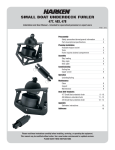
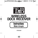
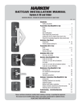
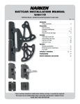
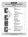
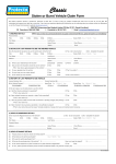
MVP Valve Panel Kit
Installation and User Manual
MVP1
MVP4
Please read these instructions carefully before using or servicing the equipment.
This manual may be modified without notice. See: www.harken.com/manuals for updated versions.
PLEASE SAVE THESE INSTRUCTIONS
NOTES
2
MVP Panel
INTRODUCTION
This manual gives technical information on installation and use. Installation, disassembly and reassembly by
personnel who are not experts may cause serious damage to property or injury to users and those in the vicinity
of the product. If you do not understand an instruction, contact Harken. The user must have appropriate training
in order to use this product.
Harken accepts no responsibility for damage or harm caused by not observing the safety requirements and
instructions in this manual. See limited warranty, general warnings and instructions at www.harken.com/manuals.
WARNING! Strictly follow all instructions to avoid an accident, damage to your vessel, personal injury or
death. Hydraulic components are capable of exerting extremely high loads. Failure to inspect and replace
faulty components may result in sudden breakage at high loads. Inspect all related equipment to ensure it
is free of defects or obstructions prior to use. Before using, make sure all people and objects are clear of
the moving components of the system.
Description
The Harken MVP Panel Kit is designed for use on sailboats and is sized according to boat and functions to be controlled.
When ordering, always have your choice confirmed by a Harken representative or other sailing professional. Other uses
of this product besides normal sailboat applications are not covered by the limited warranty.
Parts sold separately
High-quality, mineral-based, ISO 15 hydraulic oil
Cylinders to be connected to panel
High pressure hoses (Harken can supply)
Fasteners (1 /4" or M6)
Overview
Tools Required
Saw (to cut hole in boat for panel installation)
Hex driver, 5 /32"
Hex driver, 3 /16"
Drill motor and bits
Function
Suction
Return
Backstay
Installation Overview
Refer to Overview diagram when planning system
installation.
• Use enclosed template to determine optimal panel
placement.
• Locate reservoir and panel as close to each other
as possible.
• Confirm adequate clearance for pump handle
movement prior to installation.
Vang
Multifunction
valve panel/
2-speed pump
Vented
reservoir
• Confirm clearance for reservoir. Allow room above
reservoir cap for access when filling.
• Plan high pressure hose runs from panel to
functions (cylinders) and to reservoir.
• Five (5) feet of low pressure hose is included with kit.
Suction filter
Multifunction System Shown
• Remember to plan a suitable location for suction
filter along suction line between reservoir and pump.
MVP Panel3
INSTALLATION
Harken single and multifunctional valve panels are used on racers and cruisers to control systems like backstays,
boom vangs and outhauls. Offered as kits, both single and multifunctional panels come with pumps, handles,
gauge, pressure relief/release and 2- or 4-liter reservoir.
Install MVP
Connect Kit Components Using Low Pressure Hose
Review all instructions carefully prior to installation
of your new Harken MVP Panel Kit.
1. Select section of low-pressure hose for suction
line and connect from 3 /8" hose barb on pump
to either side of suction filter.
1. Carefully unpack the kit components and check for
visible defects. If any signs of damage are present,
contact your dealer at point of purchase or Harken.
2. Mount panel in selected location. Panel gaskets
and bolt holes are fitted with O-rings preventing
water from entering the hull while eliminating the
need for sealants.
3. Mount reservoir. If possible, reservoir and panel
should be mounted at the same relative height
for optimal pump suction.
4. If necessary, perform the following steps to adjust
pump handle position.
4.1 Move pump handle so one piston is fully
extended.
4.2 Remove external retaining ring and shaft
retaining washer from back of pump handle
shaft.
4.3 Without moving the pistons, rotate splined
shaft until desired handle position is attained.
Important: Shaft is splined in 7˚ increments
to allow for optimal pump handle placement.
4.4 When desired pump handle position is
attained, reinstall shaft retaining washer and
external retaining ring at back of pump handle
shaft.
4
2. Select second section of low pressure hose for
suction line and connect from other end of suction
filter to 3 /8" hose barb on bottom of reservoir.
3. Select third section of low pressure hose for
return line and connect from other 3 /8" hose barb
on bottom of reservoir to remaining 3 /8" hose barb
on relief/release valve.
Notice: Filtration is essential to the health and
longevity of your hydraulic system. Harken
supplies high-quality, cleanable, in-line filters
for use with your system. Replacement
elements are available if needed.
Setup Function Selection Handle and Valve Ports
Multi-function MVPs come with a Function Selection
Valve. This is used to select the function you want
to run. The positions on the handle are marked by a
“click” and correlate with the valve ports on the back
of the panel.
1. When installing hose lines to functions, select
a handle position for each function.
2. Attach end of hose to selected valve port.
Notice: Always remember to cap any unused valve
ports with pressure caps. The multi-function
MVP comes with two pressure caps and two
plastic caps.
MVP Panel
INSTALLATION
Connect Panel to Function(s)
Function Assignment
When reservoir is connected to panel, it is time to
connect system to function(s).
Remember these important points when measuring
the hose run from panel to function:
• Short straight runs between panel and
function are best.
• Avoid sharp edges which may chafe the hose.
• Minimize fittings/connections throughout the
run to avoid possible leak points.
• Minimize 90° bends which decrease performance.
Notice: Hoses from valve to function must be rated
to 5000 psi and must be cleaned and flushed
prior to installation.
With hose length and path set, connect high pressure
hose from pre-determined valve on panel to function.
Use the table provided to record Function Assignments
for future reference.
Add Oil
When panel is installed and functions are connected,
add filtered oil to the reservoir.
Oil Specifications: High quality, mineral based,
hydraulic oil, ISO grade 15 (ISO 20 is also suitable).
1. Pump filtered hydraulic oil into reservoir until
reservoir is 2/3- to 3/4-full.
2. Screw vented cap onto reservoir.
Outlet
Port
Return
Intake Hose
on Pump
Position
0˚
90˚
180˚
270˚
Bleed System
When reservoir is filled, the MVP system must be
bled. For multifunction systems, each function
cylinder and line must be bled separately.
Notice: Before connecting cylinder, fully extend
cylinder, pre-charge with air if required (see
manufacturer specs) and detach from rigging.
1. Select first function to be bled by turning function
selection handle to the appropriate position.
2. Close release valve.
3. Disconnect hose at function cylinder.
4. Pump oil through hose into suitable container.
When oil exiting line is bubble-free and foam-free,
reconnect hose to function cylinder.
5. If system is multifunction, repeat Steps 2 - 4
to bleed lines for each remaining function.
Otherwise, proceed to Step 6.
6. Pump until cylinder fully retracts, then open
release valve and allow cylinder to fully extend.
7. Repeat Step 6 for all functions.
When each function has been bled, and all hoses are
securely connected, MVP system is ready for operation.
Outlet
Port
Relief Valve
Outlet Ports on 4-Way
Selector Valve
Flow Control
Intake Hose
on Pump
Return
Relief Valve
MVP1
Function
Two-speed
Flow Control
MVP4
MVP Panel5
OPERATION
The Harken MVP Panel system can be selected to
operate from one (1) to four (4) functions. Follow
these simple steps for cylinder operation:
WARNING! Hydraulic components are
capable of exerting extremely high loads.
Inspect all related equipment to ensure it
is free of defects or obstructions prior to
use. Before using, make sure all people
and objects are clear of the moving
components of the system.
Single-Function System
Increase tension
1. Turn pressure release knob clockwise to close.
The resting position for the pressure release
knob is closed.
2. Move pump handle back and forth until desired
tension is achieved.
Notice: It is impossible to over-tighten the knob
or damage the valve by hand.
Multi-Function System
The multi-function MVP Panel selector valve has four
(4) positions to control up to 4 functions. Operation
of the multi-function system is similar to singlefunction except that function selection handle
must point to desired function before increasing
or decreasing tension.
1. To operate function, turn function selection handle
toward valve port to which hose is attached.
Handle clicks at 0°, 90°, 180° and 270° to indicate
when function is selected. (See Setup Function
Selection Handle and Valve Ports section for
more information.)
2. Refer to tension adjustment steps in Single
Function System section to increase or
decrease tension.
3. Place function labels at appropriate location
outside Function Selection Handle.
Notice: If additional function labels are required,
they are available, at no charge, from Harken.
Two-Speed Pump Shift
Decrease tension
1. Turn pressure release knob counterclockwise to
open. Release speed depends on how far the
knob is turned.
The two-speed pump is factory-set to shift from
first to second gear at approximately 1,500 psi.
• To increase shift point, turn flow control
clockwise to tighten.
• To reduce shift point, turn flow control
counter-clockwise to loosen.
Pump
Handle
Pressure
Gauge
Pressure
Release Knob
Function
Selection
6
MVP Panel
OPERATION
Relief Valve Adjustment
The relief valve works by preventing pump pressure
from exceeding selected valve pressure and by
allowing relief of excess shock load pressure. The
standard, factory relief setting is 4,000 psi. Maximum
possible relief setting is 5,000 psi. If relief valve
requires adjustment, perform the following steps:
1. Locate relief valve plug at bottom of valve.
2.Use 5 /32" hex driver to remove plug.
3.Use 3 /16" hex driver to turn internal adjustment
screw clockwise to increase the maximum relief
setting or turn counter-clockwise to decrease
maximum relief setting. The adjustment is
approximately 1000 psi per complete turn.
Notice: Pressure relief adjustments are made in the relief
valve and affect all functions equally. However,
for multi-function systems, the only function
affected by pressure relief adjustment at a
given time is the one selected by the Function
Selection Valve. To optimize pressure relief,
leave Function Selection Valve in position of
function which experiences most shock load
(Ex.: backstay).
To determine relief setting without tensioning the
rig, perform the following steps:
1. Disconnect cylinder from the rigging.
Use 5 / 32" hex driver to remove plug.
2. Pump cylinder until it bottoms and relief valve
opens.
3. When pumping fails to raise gauge pressure,
the maximum pressure displayed on the gauge
is the relief valve setting.
Cylinder Gauge
The easy-to-read analog gauge
has glow-in-the-dark display
and shows oil pressure in
thousands of pounds per
square inch (psi) and bar.
The gauge reads the
pressure of the function
for which the panel is set.
Refer to the Cylinder Force
vs Pressure table to convert
oil pressure to pull force.
Use 3 /16" hex driver to turn internal adjustment screw clockwise
to increase the maximum relief setting or turn counter-clockwise
to decrease maximum relief setting.
MVP Panel7
Cylinder Force vs. Pressure
Observed Pressure (gauge reading, in psi)
Size
Cylinder
HYCS02511----
-6
1000
3000
5000
Vang
lb
kg
lb
kg
lb
kg
635
288
1905
864
3175
1440
-10
HYCS03513----
1289
584
3866
1753
6443
2922
-12
HYCS04016----
1460
662
4381
1987
7302
3312
1000
3000
5000
lb
kg
lb
kg
lb
kg
—
—
—
—
—
—
—
—
HYCV04022----
—
—
—
—
—
—
106
48
2437
1105
4769
2163
-17
HYCS04516----
2098
952
6295
2856
10492
4759
HYCV04525----
177
80
3416
1550
6656
3019
-22
HYCS05519----
3316
1504
9949
4513
16582
7522
HYCV05525----
718
326
6664
3023
12609
5719
-30
HYCS06522----
4307
1954
12922
5861
21537
9769
HYCV06532----
736
334
8099
3674
15463
7014
-40
HYCS07525----
6283
2850
18850
8550
31416
14250
HYCV07532----
1600
726
13283
6025
24966
11324
-48
HYCS08025----
6855
3123
20654
9368
34423
15614
—
—
—
—
—
—
—
-60/-76
HYCS09032----
8394
3807
25182
11422
41970
19037
HYCV09038----
2081
944
17789
8069
33497
15194
Inspection
Perform a visual inspection of the MVP Valve Panel prior to each use.
Care and Maintenance
Harken products should give years of reliable service. If clean oil is used, components are properly connected and
system is properly bled, no regular maintenance is required. If you experience any problems with your Harken MVP
Panel kit, contact your Harken Service Representative.
Warranty
Harken warrants that each Harken product, when properly used and maintained, will be free from defects in
material and workmanship from the date of receipt of the product by the final customer. Harken products are
covered by two different kinds of warranties, on the basis of the purchaser and use made of them.
For complete warranty or for information relating to a specific warranty concern, please refer to the following:
Harken Catalog, www.harken.com/manuals
Call or Email the Nearest Harken Distributor or
Harken Corporate Headquarters (Telephone/Email Addresses Below)
Corporate Headquarters
N15W24983 Bluemound Rd., Pewaukee, WI 53072-4974 USA, Tel: (262) 691-3320, Fax: (262) 701-5780,
Web: www.harken.com, Online Catalog: www.harkenstore.com, Email: [email protected]
Harken Adriatik d.o.o.: Obala 107, 6320, Portoroz, Slovenia, Tel/Fax: (386) 5-6774122, Web: www.harken.si, Email: [email protected]
Harken Australia Pty, Ltd.: 1B Green Street, Brookvale, N.S.W. 2100, Australia, Tel: (61) 2-8978-8666, Fax: (61) 2-8978-8667,
Web: www.harken.com.au, Email: [email protected]
Harken France: ZA Port des Minimes, BP 3064, 17032, La Rochelle Cedex 1, France, Tel: (33) 05.46.44.51.20 • Fax: (33) 05.46.44.25.70,
Web: www.harken.fr, Email: [email protected]
Harken Italy S.p.A.: Via Marco Biagi, 14, 22070 , Limido Comasco (CO) Italy, Tel: (39) 031.3523511, Fax: (39) 031.3520031, Web: www.harken.it, Email: [email protected]
Harken New Zealand, Ltd.: 30-36 Fanshawe Street, P.O. Box 1951, Auckland 1001, New Zealand, Tel: (64) 9-303-3744, Fax: (64) 9-307-7987,
Web: www.harken.co.nz, Email: [email protected]
Harken Polska SP ZOO: ul. Rydygiera 8, budynek 3A, lokal 101, I piętro, 01-793, Warszawa, Poland, Tel: +48 22 561 93 93, Fax: +48 22 839 22 75,
Web: www.harken.pl, Email: [email protected]
Harken Sweden AB: Main Office and Harken Brandstore: Västmannagatan 81B, SE-113 26 Stockholm Sweden, Tel: +46 303 618 75.\, Fax:+46 303 618 76,
Mailing address: Harken Sweden AB, Box 64, SE -440 30 Marstrand, Email: [email protected]
Harken UK, Ltd.: Bearing House, Ampress Lane, Lymington, Hampshire S041 8LW, England, Tel: (44) 01590-689122, Fax: (44) 01590-610274,
Web: www.harken.co.uk., Email: [email protected]
Please visit: http://www.harken.com/dealers/dealers.php for an up-to-date list of Harken dealers and distributors
Please visit: http//www.harken.com/dealers/dealers.php
for an up-to-date list of Harken dealers and distributors
Printed in USA 4343 08/13