1
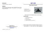
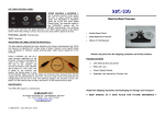
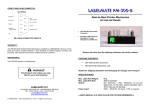
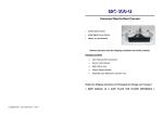
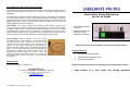
ADJUSTING THE LABEL DETECTOR PHOTOCELL:
LABELMATE PM-300
The machine has two (2) photo detector cells. The first one (closest to the front) is used to
detect and count the labels. The second one is used for “out of paper” condition and is not
adjustable.
Reel-to-Reel Printer Mechanism
for Ink-Jet Heads
The label detector photocell has been adjusted at the factory and requires no adjustment
for a large variety of labels. However, some specific labels (very transparent or relatively
opaque backing paper) might require adjustment of the photocell. The photocell can be
adjusted in two ways, one is by using the “gap” indicator, the other one is to use the test
cable provided and measure the voltage.
First method: Load a roll of labels on the machine, put the speed to minimum (not
moving), remove one label and position the backing paper in front of the first photocell.
Press the “START” button, the yellow “Gap” led should not light, if it does, you can adjust
the potentiometer on the left side of the machine. The adjustment can be done with a
small flat blade screwdriver. Now, put a label in front of the photocell, the yellow “Gap” led
should now light-up. Be sure that the labels are tensioned when doing the test.
Second method: Using a voltmeter, you can do a more
accurate adjustment of the photocell. Connect the provided
test cable to the “TEST” connector on the side of the
machine and connect the leads to a DC voltmeter with a
range of +/- 20V. Load a roll of labels on the machine, no
need to push the “START” button, and position the backing
paper in front of the first photocell. Set the voltage with the
potentiometer to around 5V, now put a label in front of the
photocell; the voltage should now be 10V or more. The
reference voltage in the machine is set at 7.5V, below 7.5V
the machine sees no label, and above 7.5V the machine
sees a label.
•
Secured DB-9 Print Head
Connector
•
Encoder 2.048 Pulses per
Revolution = Linear
Resolution of 0.0407-mm.
Remove all parts from the shipping container and verify contents.
Package Contents
•
User Manual (this document)
•
PM-300 Printer Mechanism Unit
•
Power Supply Module
MAINTENANCE:
Your PM-300 requires no maintenance.
Retain the Shipping Container and Packaging for Storage and Transport
LABELMATE LLC
69 AVENUE ALPHONSE XIII, 1180 BRUSSELS, BELGIUM
TEL: +322.375.69.60 – FAX: +322.375.38.96
[email protected]
www.labelmate.com
© LABELMATE – User_PM-300 – 05/098
● KEEP MANUAL IN A SAFE PLACE FOR FUTURE REFERENCE
SPECIFICATIONS:
LEFT SIDE CONTROL PANEL:
Max. Label Roll Weight: 6Kg (13.2Lb)
Max. Label Roll Size:
300mm (12") diameter
Speed:
Min. 65cm/sec (25-ips) – Max. 150cm/sec (59-ips) for LS and
220cm/sec (87-ips) for HS. Max. speeds specified with a 76mm
take-up roll diameter.
Power Supply:
100-230V – 50-60 Hz. AC Input. DC Output: 24V @ 4.17A
SPEED VARIABLE or MAXIMUM: A two
(2) position Selector Switch allows the
user to select maximum (MAX) speed (not
adjustable) or adjustable speed set by the
front panel Speed Control Knob. The
maximum speed in the "VARIABLE"
position with the SPEED potentiometer
fully clockwise is about 10% lower than
the speed obtained in the "MAX" Speed position of the Speed Switch. When the printing
is correct, the unit can be used at MAX. Speed at all times.
SET-UP:
1.
Plug the Power Supply Output Cable to the Power Jack on the Rear Panel of the PM300. Plug the Power Supply into a suitable AC Power Mains Outlet. Place the Power
Switch on the rear of the PM-300 to the “ON / 1” position.
2. The Optional Counter (if included) is pre-programmed as a Preset Count-Up
Counter. To use the preset function, input the desired number of labels with
the Push Buttons on the Counter. If you do not use preset, set the value to
“0”.
3.
When the preset number of labels is reached, the PM-300 will stop. Pressing
the “Reset” on the Counter will reset the count to zero so the PM-300 can be
started again. A duplicate Reset Switch is located on the left side of the unit.
FRONT CONTROL PANEL:
POWER (GREEN): Indicates power is applied to the unit. The
ON-OFF Power Switch is on the rear of the Unit.
ERROR / STOP (RED): Indicates that either the unit is in
STOP mode or one of the three Error Conditions has occurred:
1. The unit is Out Of Paper.
2. The counter has reached the Pre-Set Value.
3. There is a Print Head Error condition. e.g.: No more ink
(condition valid only if the Print Head supplies this signal).
INK LOW (RED): Indicates that the Print Head has sent an Ink-Low Signal.
GAP (YELLOW): Flashes when Unit is running, indicating proper detection of the Gap
between successive Labels.
START BUTTON (WHITE): Start printing, if no Error Condition is present.
STOP BUTTON (RED): Holding down this button will stop the machine when the next gap
passes in front of the photocel.
SPEED CONTROL: Varies the speed from zero to maximum.
COUNTER RESET: Duplicate Counter Reset Switch performs same function as Rest
Button on the Counter Module itself.
PHOTOCELL ADJUST: Potentiometer.
TEST: Connector .
See Adjusting the Label Detector Photocell.
See Adjusting the Label Detector Photocell.
CONTROLS & HEAD CONNECTOR ON REAR OF THE UNIT:
DB-9 FEMALE
Encoder A
1
Encoder B
2
Photo
Groundcell
3
(open collector) 24V
Head Error
5 up to 15V DC
6
Gap
(open collector)
7
No connection
8
Ground
GND
4
9
(Optional) +24v
Encoder
(square
wave 0-15V)
15v
5
DB-9 HEAD CONNECTOR PINOUTS
DO NOT CHANGE DIRECTION
WHILE THE MACHINE IS RUNNING.
THIS COULD PERMANENTLY
DAMAGE THE MACHINE.
WARRANTY:
The PM-300 Reel-to-Reel Printer Mechanism is backed by LABELMATE’s famous 3-Year
Parts and Labour Limited Warranty.
WARNING!
This Product is for indoor use only.
Not for use in wet locations.