1
SOFTWARE USER GUIDE
CrossCore XA
Software User Guide
www.crosscontrol.com
Date: Oct 25, 12
CrossCore XA
Software User Guide
Date: Oct 25, 12
Contents
Revision history ..................................................................................................................................3
1. Introduction ..................................................................................................................................4
1.1. Purpose ........................................................................................................................................ 4
1.2. Conventions ............................................................................................................................... 4
1.3. References .................................................................................................................................. 4
2. Device Introduction .....................................................................................................................5
2.1. Bootstrap Software .................................................................................................................... 5
2.2. Linux system ................................................................................................................................ 5
2.3. Start-up sequence..................................................................................................................... 5
2.4. Boot count .................................................................................................................................. 5
2.5. Shutdown sequence ................................................................................................................. 5
2.6. Status led operation .................................................................................................................. 6
3. System Management and Configuration .................................................................................7
3.1. User accounts ............................................................................................................................ 7
3.2. File system ................................................................................................................................... 7
3.3. System clock ............................................................................................................................... 7
3.4. User configuration files.............................................................................................................. 8
3.5. User libraries .............................................................................................................................. 11
3.6. User binaries .............................................................................................................................. 12
4. Accessing CrossCore ................................................................................................................13
4.1. Remote access ........................................................................................................................ 13
4.2. Local access ............................................................................................................................ 18
5. Hardware Module Interfaces ....................................................................................................19
5.1. Ethernet ..................................................................................................................................... 19
5.2. CAN ............................................................................................................................................ 19
5.3. USB host ..................................................................................................................................... 19
5.4. USB device ................................................................................................................................ 19
5.5. RTC ............................................................................................................................................. 20
5.6. EEPROM ..................................................................................................................................... 20
5.7. Temperature sensor ................................................................................................................ 21
5.8. Front LED .................................................................................................................................... 22
5.9. Digital input and output ......................................................................................................... 22
5.10.
DFC or Compact Flash ................................................................................................... 23
5.11.
GPS ..................................................................................................................................... 24
5.12.
GSM/GPRS ........................................................................................................................ 24
5.13.
WLAN ................................................................................................................................. 25
5.14.
Bluetooth ........................................................................................................................... 26
5.15.
Accelerometer ................................................................................................................. 26
6. Linux Development Hosts ..........................................................................................................27
6.1. Retrieval of tool chain ............................................................................................................ 27
6.2. Installing tool chain ................................................................................................................. 27
6.3. Using tool chain ....................................................................................................................... 27
www.crosscontrol.com
CrossCore XA
Software User Guide
Date: Oct 25, 12
6.4. Debugging remotely .............................................................................................................. 28
7. Update of CrossCore XA software ...........................................................................................29
7.1. Released image files ............................................................................................................... 29
7.2. Released development files.................................................................................................. 29
7.3. Updating with web interface ................................................................................................ 29
7.4. Updating from console .......................................................................................................... 30
7.5. Update automation ................................................................................................................ 31
7.6. USB Autorun .............................................................................................................................. 32
7.7. Updating backup system....................................................................................................... 32
7.8. Updating unit using SAM-BA .................................................................................................. 33
7.9. Updating user software with web interface ....................................................................... 34
7.10.
Updating FPGA code from console ............................................................................ 35
8. Default Start-up Log ...................................................................................................................37
Technical Support ...........................................................................................................................38
Trademark, etc. ...............................................................................................................................38
Revision history
Rev
1.0
1.1
Date
2010-07-01
2011-10-20
1.2
2012-06-18
1.3
2012-10-25
www.crosscontrol.com
Comments
Updates to section 7.9, clarifying the Web
interface
Updates to 5.12, how to accuire GSM/GPRS
modem power status
3
CrossCore XA
Software User Guide
Date: Oct 25, 12
1. Introduction
This document is primary user guide for CrossCore XA and CrossCore XA All-Integrated devices.
1.1. Purpose
This user guide contains information of how to access the CrossCore XA products running the
Linux operating system.
Information about configuration files and how to access different hardware modules are also
described in this document.
A good prior understanding of Linux systems is needed to fully benefit from this documentation.
1.2. Conventions
Text formats used in this document.
Format
Italics
Bolded
Use
Paths, filenames, Product names.
Command names and important information
Is used to highlight important information.
1.3. References
[1] CrossCore XA – Programmers Guide
[2] CrossCore XA – Release Notes
www.crosscontrol.com
4
CrossCore XA
Software User Guide
Date: Oct 25, 12
2. Device Introduction
This chapter gives an overall description of the CrossCore XA device software.
2.1. Bootstrap Software
The boot loader of the CrossCore XA device is at91bootstrap. It is not interactive and its only
responsibility is to load the Linux kernel into RAM memory from NAND flash, and start executing
the Linux kernel.
2.2. Linux system
The device can be started into two different modes.
Normal system: this is the main operation mode. This mode includes all drivers to available
hardware, system libraries and tools described in this and other documents.
Backup system: this is only for device updating and recovery use. It contains only basic
maintenance tools. Updating the main system is done from backup side. Most of the hardware is
not available while on backup system.
2.3. Start-up sequence
After power is connected to CrossCore XA device the normal system will start-up:
1.
Bootstrap software executes. Status LED is static AMBER.
2. Linux is checking the system. Status LED is AMBER flashing at 15Hz.
One time tasks, like key generations after factory reset is performed in this stage.
3. Linux is loading hardware drivers. Status LED is AMBER flashing at 2Hz.
User mode execution possible, although all drivers and devices might not be ready.
4. System is up. Status LED is static GREEN.
All systems go, although DHCP received Ethernet addresses might activate bit later.
2.4. Boot count
If main system fails to boot successfully for 5 times in a row, the device will automatically boot to
backup system instead of main system. The reason for failed main system boot can then be
examined and corrected in backup system.
As a control point, the boot is deemed successful if the system start-up process gets to level 60. This
means that the script file /etc/rc3.d/S60system-up executes successfully.
It is possible to start user applications before or after this control point. See chapter 3.4.6 for a
description of start-up scripts.
2.5. Shutdown sequence
Once shutdown or reboot is initiated:
1.
Shutting down, Status LED is AMBER flashing at 7Hz
2. Device is off, Status LED if OFF
www.crosscontrol.com
5
CrossCore XA
Software User Guide
Date: Oct 25, 12
2.6. Status led operation
Summary of status led modes:
LED state
OFF
GREEN ON
GREEN
flashing 2 Hz
AMBER ON
AMBER
flashing 2 Hz
Meaning
Device is OFF
Device is ON in main system
Device is ON
in backup system
Device in BOOT mode
Device in BOOT mode
AMBER
flashing 7 Hz
AMBER
flashing 15 Hz
RED ON
Device is shutting down
RED
Flashing 2 Hz
RED
Flashing 7 Hz
Firmware Update
www.crosscontrol.com
System Check
Device is faulty
System repair and recovery
Comments
No power applied or a broken device
Working with no errors detected
Working in backup system side
Boot loader and kernel execution
User space execution, possibility that
some hardware peripherals have not
started working
Normal shutdown initiated
System checking file systems and
similar actions
Internal fault or life-time of the device
ending
Device is updating the firmware
System running factory reset system
and clearing out all user data
6
CrossCore XA
Software User Guide
Date: Oct 25, 12
3. System Management and Configuration
3.1. User accounts
There are two user accounts created in the system at start-up, the root user and cross_admin user.
The password for the cross_admin user is 123cross345. Cross_admin user is available for normal
device use, for example running customer applications.
The password for the root user is suseroot. Root is standard Linux root-user which can do
everything possible, including maintenance task.
Additional users cannot be created.
3.2. File system
The root file system is located in NAND flash memory. It is of type UBIFS and it is mounted as
read-only for security reasons. It is mounted by the kernel boot-up sequence. The optional
DFC/Compact Flash card is also mounted during boot-up. The Compact Flash card is formatted
with an ext3 file system.
Any attached USB memory is automatically mounted once inserted. Supported formats for USBmemory include FAT which is the default format for USB-memories. USB-memory devices are
never automatically formatted so if file system is unsupported, device is just not mounted.
Mount point
/
/usr/local
/media/cf
/media/usb
/media/usb2
/tmp
/var
Mount status
Read only
Read-write
Read-write
Read-write
Read-write
Read-write
Read-write
Media
NAND flash memory
NAND flash memory, secondary partition
DFC/Compact Flash
USB memory, if available
Second USB memory, if available
RAM memory, for storing temporary files
RAM memory, for storing logs etc. during runtime
The /usr/local/ partition of NAND flash contains some default configuration files, but most of its
space is reserved for application programs. It is up to the user to decide which applications to run.
3.2.1. Wear leveling
As all flash memory devices have limited write cycles, wear leveling is an important issue. Effect is
minimized by rotating the physical block where write access occurs. For /media/cf/ the Compact
Flash handles this internally with its own controller. For /usr/local/ the selected file system is
UBIFS, which does the same with NAND flash.
User can prolong the device age by keeping sure that the device has as much free space as possible
so that the leveling function has enough free blocks to rotate writes with.
3.3. System clock
The system schedule clock is 1000Hz or 1ms.
www.crosscontrol.com
7
CrossCore XA
Software User Guide
Date: Oct 25, 12
3.4. User configuration files
The folder /usr/local/etc/ contains several configuration files, which are made available in a
default version. These files can easily be replaced with specific customized versions if required. This
chapter contains a brief description of the default configuration files and their usage.
3.4.1. Host name configuration
The device host name is supplied by user configurable file /usr/local/etc/hostname. This file is
created with a default host name at initial start-up. The user can then replace the file to set a
specific host name.
If the file is removed, it will be restored to default state upon next system boot.
3.4.2. Time zone configuration
A time zone configuration normally points to a file containing time zone data. These time zone
configuration files are located in /usr/share/zoneinfo/ or in subdirectories in that directory. To
select a time zone, create a symbolic link file /usr/local/etc/localtime to point to the appropriate
time zone data file under /usr/share/zoneinfo/.
If the /usr/local/etc/localtime-file does not exist at start-up, a default version is created to use UTC
time zone settings.
3.4.3. Network interfaces configuration
The network interfaces configuration file is located in /usr/local/etc/interfaces. This file is
configured to use one Ethernet interface with DHCP IP retrieval. It can be edited to change the
default setup of the network interfaces on the target. For instance, it can be configured to use a
static IP address on one interface and a DHCP address on the other interface, if two interfaces are
required. The /etc/network/interfaces file is a symbolical link to the /usr/local/etc/interfaces file.
For further information on how to write this file, see ‘interfaces’ man pages.
If the /usr/local/etc/interfaces–file does not exist at start-up, a default version is created from
template.
3.4.4. DHCP client
The template DHCP client configuration file, called dhclient.conf.new, located in /usr/local/etc is
used for creating the /usr/local/etc/dhclient.conf configuration file. This file must contain the
actual host name to be used. The template file dhclient.conf.new can be replaced with another
configuration file, as long as the host name entry remains “HMI_eth0” in that file. This string is
replaced with the actual host name in the dynamically created file, which is created on every startup. For further information on how to write this file, see ‘dhclient’ man pages.
If the /usr/local/etc/dhclient.conf.new–file does not exist at start-up, a default version is created
from template. The default version looks like:
# Wa i t ver y lon g ti me , a p pr ox 3 ,5 d a ys i s 300000 sec on d s
ti me ou t 3 00000 ;
re tr y 0 ;
re b oo t 0 ;
b ac koff -cu toff 4 ;
# se lec t- ti me ou t 5 ;
#i ni ti al -i n ter val 2 ;
www.crosscontrol.com
8
CrossCore XA
Software User Guide
Date: Oct 25, 12
s en d h o s t-n a me " HMI _et h0 " ;
# Thi s ma kes the d hcp -p ar a me te r -re que s t- op ti o n
re que s t sub ne t- ma s k , br oa dc a s t - a dd res s , ho s t - na me , r ou ter s ,
d o mai n -n a me , d o mai n -n a me- ser vers , n tp - ser vers ,
dhc p -le a se - ti me , d hc p - me ss a ge - ty pe ,
ven dor -enc a psu l a ted - o pti ons ;
3.4.5. NTP
The NTP configuration file should be located as /usr/local/etc/ntp.conf. This file should not
contain any server sections since the DHCP request process will use this configuration file as a
template to create the ntp.conf.dhcp file with NTP server settings from the DHCP reply. Note that
the latter file exists only in temporary file system, and is regenerated on every DHCP request/reply
cycle. Once this file exists, NTP daemon is restarted with the new configuration file. For more
information about NTP and its configuration file, see ‘ntpd’ man pages.
If the /usr/local/etc/ntp.conf–file does not exist at start-up, a default version is created from
template.
3.4.6. Start-up scripts
The user has the possibility to start applications and scripts by modifying or adding start-up scripts.
When the kernel is started, the start-up script rc located in /etc/init.d/ is executed. Normally, this
script reads start-up scripts under /etc/rcX.d/, depending on the actual run level X.
The default run level is 3, which is basically the only run level in this system. The rc script has been
modified so that it parses start-up scripts found in either /etc/rcX.d/ and /usr/local/etc/rcX.d/.
The parsing is done in a temporary directory, so scripts from each source location are interleaved
depending on their respective names as described below.
To start applications in run level 3, create a script located in /usr/local/etc/rc3.d/ that starts the
desired applications. This is the default run level. Each script must be named SXXname, where XX
is two digits and corresponds to the order when the script is run. Also note that these scripts are
usually sourced, so no exit should be performed within these scripts.
Run level 6 is dedicated for shutdown. When device is shutting down the scripts from /etc/rc6.d/
and /usr/local/etc/rc6.d/ are executed to perform last clean-up actions. Required naming and
execution order rules comply with start-up level 3.
3.4.7. SSH files
At initial start-up, the SSH keys are automatically generated and stored in folder
/usr/local/etc/ssh/. This generation process may cause the start-up to be delayed for
approximately 10 seconds. Once generated, the key files are not regenerated again unless they are
removed. These files should not normally be edited, but they may be replaced with specific key files,
if desired. For more information about this, see http://matt.ucc.asn.au/dropbear/dropbear.html.
3.4.8. Logrotate configuration file
The logrotate configuration file /usr/local/etc/logrotate.conf is not available by default. It is up to
the user to create the file for appropriate logging, and to start the logrotate service. Logrotate is
www.crosscontrol.com
9
CrossCore XA
Software User Guide
Date: Oct 25, 12
started at boot time only if the configuration file exists. Logrotate reads everything about the log
files it should be handling from the configuration file. Each configuration file can set global options
(local definitions override global ones, and later definitions override earlier ones) and specify logfiles to rotate. For more information on how to write the logrotate configuration file, see ‘logrotate’
man pages.
To start the logrotate service, do the following manually (or reboot the unit for same effect):
~ # /e tc/i ni t .d/ lo gr o t ate s t op
~ # /e tc/i ni t .d/ lo gr o t ate s t ar t
Logrotate can be used for compressing and moving latest log files to /usr/local/ for safekeeping.
Normally it is run at a 30 minute interval.
3.4.9. Watchdog configuration file
The device has a hardware watchdog that resets the device power. The watchdog can be controlled
by the user. The watchdog timeout is 16 seconds by default, and can be changed using configuration
file /usr/local/etc/watchdog_timeout.conf. The file should contain only a single numeric value on
first line – that value is the requested timeout in seconds.
Valid values are from 0 to 16. Using a value zero (0) disables the watchdog.
3.4.10. Bluetooth configuration file
Bluetooth is only available as an option in CrossCore XA All-Integrated devices.
The Bluetooth configuration files are located at /usr/local/etc/bluetooth/. Two example
configuration files main.conf and rfcomm.conf are also in that folder. Bluetooth is not activated at
boot time. It is up to the user to setup Bluetooth connections.
To activate Bluetooth, do the following manually:
~ # hci confi g hci 0 u p
3.4.11. GPS configuration file
GPS is only available as an option in CrossCore XA All-Integrated devices.
GPS has no default configuration files. See 5.11 for more information.
3.4.12. GSM/GPRS configuration file
GSM/GPRS is only available as an option in CrossCore XA All-Integrated devices.
GSM/GPRS has no default configuration files. See 5.12 for more information.
3.4.13. WLAN configuration file
WLAN is only available as an option in CrossCore XA All-Integrated devices.
WLAN uses no default configuration files, although one exists. See 5.13 for more information.
3.4.14. Accelerometer configuration file
Accelerometer is available as an option in CrossCore XA All-Integrated devices.
Accelerometer has no configuration files. See [1] for more information.
www.crosscontrol.com
10
CrossCore XA
Software User Guide
Date: Oct 25, 12
3.4.15. Serial Number Broadcast configuration
Serial Number Broadcast (SNB) is started by default at device boot-up and it will broadcast a
specific identification message to the local network every fifth second. The message send frequency
can be modified and the service can be completely disabled, using the configuration file
/usr/local/etc/ccsnb.conf. That file does not exist by default. Default values are used if any value is
unset or the file does not exist.
# Seri a l Nu mb er Bro a dc as t – co nfi gur a ti on .
# Li ne s b e gi nni ng wi th ‘ # ’ are co mme n ts . Unne ces s ar y o p ti on s c an b e o mi tte d .
# Me s sa ge sen d i n ter va l i n sec on d s
I NTER V AL = 1 0
# Ser vi ce di s ab le s wi tch (DI S AB L E |O F F |0 )
# AC TI VE = DI S AB L E
# Ad va n ce d fe a ture s on ly . Use wi th di scre ti on .
#
# Fi r mw are -fi e l d i s au t o di sc o ver ed , bu t c an be o ver wri tten . S tri ng val ue
# FI RM WAR E = 1 .0 .0
#
# U ni t Ty pe -fi el d i s TB D , i f un se t '0' i s us ed . S tri ng va lue
# U NI TTYP E = X A
#
3.4.16. Power monitor configuration
The power monitor is started by default at device boot-up. It monitors power state to ensure safe
shutdown in case of a power failure.
It is possible to implement a customized power monitor. If a customized power monitor is to be
used, the default power monitor needs to be disabled. This is done by creating file
/usr/local/etc/disable-powermonitor. Contents of the file is not important, it can be an empty file
as well. Note that in a power failure, after user software has done its activities, the script
/usr/bin/post-powerfailure should be executed, in order to report power failure to the system.
3.5. User libraries
To install additional shared libraries, install the library files into /usr/local/lib/. Then, update the
used library cache file by executing the following command:
~ # l dc onfi g - C /u sr/ loca l /e tc/ ld .s o .c ache
If additional library file locations are needed, the paths of these can be added to above command as
parameters. The environment variable $LD_LIBRARY_PATH can also be used to find library files
not in the cache.
Library cache file is never automatically updated. But if the file does not exist at system start-up, it
is re-created with default version containing info only about the standard libraries.
www.crosscontrol.com
11
CrossCore XA
Software User Guide
Date: Oct 25, 12
3.6. User binaries
Additional binaries such as customer application software or additional open-source solutions are
preferably installed to /usr/local/bin/ or /usr/local/sbin/. These directories are available in the
standard path, so adding binaries to these locations does not require an update to the $PATH
environment variable.
If additional levels of binaries are required, the $PATH environment variable must be updated
through a start-up script.
www.crosscontrol.com
12
CrossCore XA
Software User Guide
Date: Oct 25, 12
4. Accessing CrossCore
There are several ways to communicate with the CrossCore XA, either using local or remote access.
4.1. Remote access
The methods described in this chapter require an IP address being assigned to the CrossCore XA
device. There are several ways of setting the IP address of a device. The default method is DHCP,
but this can be changed by editing the file /usr/local/etc/interfaces. For instance, it is possible to
set a static IP address if desired.
4.1.1. SSH
To connect to the CrossCore XA device, issue the following command (and give password when
asked):
# s sh ro o t@X .X .X .X
User account cross_admin can also be used.
To connect to a host from the CrossCore XA device, issue the following command:
~ # s sh U sern a me @X .X .X.X
Above X.X.X.X is known as an SSH server IP address, with username Username. A password might
be necessary.
4.1.2. SCP
To copy a file to target use the following command (and give password when asked):
# sc p Fi l e1 r oo t @X .X .X .X :/usr /l oc al/ Fi l e1
To copy a file from the CrossCore XA device to a host, use the following command:
~ # sc p Fi le U sern a me @X .X .X .X :Fi le
Above X.X.X.X is known as an SSH server IP address, username Username. A password might be
necessary.
4.1.3. Password-free login for SSH and SCP
Even though the root or cross_admin user has password, SSH-connections can be configured to
connect without password, using identity files. This method is mainly useful for remotely executed
scripts or alike.
On connecting host (not the target CrossCore XA), execute the command below and enter an empty
passphrase when prompted.
~ $ s sh -k ey ge n - t rs a -f xa 1_rs a
Copy (or append) the created xa1_rsa.pub file into target CrossCore XA as
/usr/local/etc/ssh/authorized_keys -file.
www.crosscontrol.com
13
CrossCore XA
Software User Guide
Date: Oct 25, 12
Move the xa1_rsa file to a usable location (e.g. ~/.ssh/ )
Either configure that id-file into use in your ssh_config or use it from location when executing ssh
or scp.
~ $ s sh -i ~/ .s sh/ x a1_rs a r oo t @X A1
4.1.4. Remote command execution
After password-free login is enabled, any commands can be started remotely "without login".
~ $ s sh r oo t @X A1 " l s -a l /u sr/ loc a l/ "
If starting services or "background" tasks, append "&" to command between quotes.
4.1.5. SFTP
CrossCore XA has an in built FTP server to be used for remotely upload or download information
from the unit.
The SFTP uses the same login information as SSH.
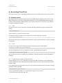
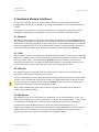
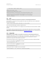
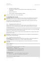
4.1.6. HTTP
The device has a built in web server for software update and configuration features. It is accessed
with a known host name (DNS resolved) or through a known IP address. A standard web browser
can be used to access the web interface.
Screenshot below shows the login screen. User accounts root and cross_admin can be used.
Screenshot: Web GUI, login screen
www.crosscontrol.com
14
CrossCore XA
Software User Guide
Date: Oct 25, 12
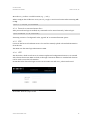
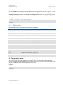
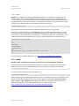
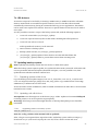
User software is uploaded to device and clean-up actions performed using User Software page.
More details in 7.9:
Screenshot: Web GUI, User Software page
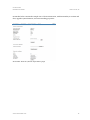
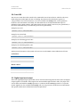
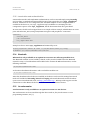
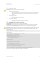
Properties of both accounts can be edited in the User Settings page, shown below.
Screenshot: Web GUI, User Settings page
www.crosscontrol.com
15
CrossCore XA
Software User Guide
Date: Oct 25, 12
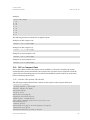
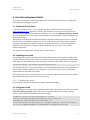
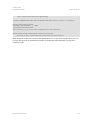
Screenshot below contains the sample view of device information, with functionality to set time and
date, upgrade system firmware, and set networking properties.
Screenshot: Web GUI, Device Information page
www.crosscontrol.com
16
CrossCore XA
Software User Guide
Date: Oct 25, 12
Screenshot below contains the sample view of Service page. It’s mainly intended for service people.
Backups from the device can be requested and an overall status of the device can be seen on this
page.
Screenshot: Web GUI, Service page
www.crosscontrol.com
17
CrossCore XA
Software User Guide
Date: Oct 25, 12
4.2. Local access
Local access to device can be made using SSH as above. Local terminal connection to the device,
described below, is not possible without additional options.
4.2.1. Debug card
Debug card is additional peripheral for CrossCore XA devices.
Debug card is an additionally available hardware peripheral. This external module contains various
debug and development use connectors, such as JTAG and serial ports. It is connected to a
connector under CrossCore XA device’s bottom plate.
4.2.2. Debug serial access
This method requires that a serial cable is connected to the serial port connector on additional
debug card. Normally, this is used only for service, development and major maintenance cases.
The serial port settings to be used when communicating with the target are 115200-8-N-1. The
serial interface is currently used as the console during the boot phase. When the system is up and
running, it is also possible to use the console as a login facility, giving “physical” access possibilities
with the getty program on device /dev/ttyS0.
If PC does not have serial port available, dedicated USB-serial cable can be used together with the
debug card to achieve same serial access.
www.crosscontrol.com
18
CrossCore XA
Software User Guide
Date: Oct 25, 12
5. Hardware Module Interfaces
The CrossCore XA and CrossCore XA All-Integrated devices can have different hardware
configurations. Therefore, your module may not have all the hardware devices described in this
chapter.
This chapter covers the software aspects of the interfaces. Consult the User Manual for more
information regarding the actual hardware. Also see 5.6 for module specific information.
5.1. Ethernet
The Ethernet device appears as eth0. The Ethernet device is initialized with the ifplugd daemon
which monitors the device for link status. Upon change of that status, it performs different actions.
By default, it invokes the ifup/ifdown scripts, which in turn verifies which settings to use with the
interfaces configuration file, i.e. to use DHCP or static IP, before actually setting up the interface
and retrieving the IP address either statically or dynamically with DHCP-client dhclient.
5.2. CAN
The CAN driver is built as a loadable kernel module, which is loaded at system start-up, if the CAN
hardware is available. The two CAN interfaces are accessible through network interfaces can0 and
can1 respectively; they can be listed with the ifconfig command. The driver uses the Linux
Network and Sockets Layer, providing the SocketCAN method of accessing the CAN buses. For
more information about the CAN driver and its API, see the Programmers Guide.
5.3. USB host
The USB port supports USB memory sticks. Certain memory sticks may not work due to the
restrictions of the internal USB Host Controller chip.
Up to two USB memories can be automatically mounted upon insertion. The mount points will be
/media/usb/ for the first and /media/usb2/ for the one plugged while other is already mounted.
Care must be taken on memory device removal. Umount should be called or reasonable time
waited after all writing actions before unplugging memory.
Most common USB memory file system formats are supported, including but not limited to
FAT16/FAT32 and EXT2/EXT3.
5.4. USB device
The USB device port acts as an Ethernet over USB device. To use it with Windows, an inf – file,
which instructs Windows to use the correct driver, is needed. Pre-existing RNDIS – driver is used
to communicate with Windows. In Linux the device should work without any external files.
Configuration of the USB Ethernet device is done using the normal method as in 3.4.3.
Device can be configured to either static or dynamic IP. In static mode the device uses a static IPaddress and starts up a DHCP server which provides an IP-address for the connecting PC. In
dynamic mode the device requests IP-address from the DHCP at the PC.
www.crosscontrol.com
19
CrossCore XA
Software User Guide
Date: Oct 25, 12
5.5. RTC
There is a battery backed up RTC on the CrossCore XA device. Date command modifies the system
time only. The hwclock command can be used to transfer system time to and from the RTC.
Normally, start and stop scripts are used for restoring and saving the RTC time in the unit. Note
that if NTP is properly set up and available, it might override the RTC clock during start-up.
5.6. EEPROM
Module EEPROM is only available in CrossCore XA All-Integrated devices.
There are two EEPROMs in a CrossCore XA device and three EEPROMs on CrossCore XA AllIntegrated device. The two common EEPROMs are accessed as /dev/serial-eeprom, /dev/usereeprom. The additional CrossCore XA All-Integrated device is /dev/module-eeprom. All available
EEPROMs can be read, whilst only user EEPROM can be written by the user.
To read and write an EEPROM, use a standard tool or API for reading and writing files, i.e. dd
program or write() and read() functions. The lseek() and mmap() functions are not supported.
Up to 4095 bytes can be written or read.
The serial EEPROM and module EEPROM contains information about the device and are set at the
factory. The device node appears in /dev/serial-eeprom. It can be read as a normal file, but it
cannot be written to. This is to protect the data from unintentional overwriting.
Note that the data in serial and module EEPROMs is DOS formatted (carriage return + new line
character).
Example:
~ # ca t / de v/ seri al -ee pr o m
D AT A:1
P C B_ S ERI AL :S 001 30503
U NI T_ S ERI AL :S 00000003
D ATE :2 009 -1 0-12
H WVE R SI O N:P A1
E TH :1
M AC 1 :00 -50- C2-18 -98- D8
DI GI O :2
C AN :2
U S BD E V:1
U S B HO S T:1
S E RI AL :0
C F :4
~ # ca t / de v/ mo d ul e -ee pr o m
M OD_ D AT A:1
M OD_ P CB_ S ERI AL :S 0 0140500
M OD_ D ATE :2 009 -11-05
M OD_ H WVE R SI O N:P A1
WL AN :1
WL ANM AC 1 :0 0 -5 0-C2 -18 - A9 - 0C
G P S :0
G S M :1
B LU E TO O TH :0
www.crosscontrol.com
20
CrossCore XA
Software User Guide
Date: Oct 25, 12
The user EEPROM is available for the user. The device node appears in /dev/user-eeprom. To read
and write an EEPROM, use a standard tool or API for reading and writing files, i.e. dd program or
write() and read() functions. The lseek() and mmap() functions are not supported. Up to 4095
bytes can be written or read.
Example:
~ # ech o “ my s tri n g” > /d e v/ user -ee pr o m
~ # ca t / de v/ user -ee pro m
my s t ri n g
5.6.1. EEPROM data
Integral value fields in read-only serial and module EEPROMs:
Keyword
PCB_SERIAL
UNIT_SERIAL
DATE
PROD_REV
HWVERSION
MAC1
DIGIO
CAN
USBDEV
USBHOST
SERIAL
CF
Value
Serial number of PCB board
Serial number of device, same as written on device brand label.
Manufacturing date
Product revision
Version of HW
MAC address of the Ethernet device
Number of digital I/O connectors (2/1/0)
Number of CAN channels (2/0)
Existence of USB Device port (1/0)
Existence of USB Host port (1/0)
Existence of Serial port connector (1/0)
Size of Internal CF-card (Gigabytes, 0/4/8)
MOD_PCB_SERIAL
MOD_HWVERSION
WLAN
WLANMAC1
GPS
GSM
BLUETOOTH
Serial number of CrossCore XA All-Integrated module PCB
Version of CrossCore XA All-Integrated module HW
Existence of WLAN device (1/0)
MAC address of the WLAN device
Existence of GPS device (1/0)
Existence of GSM/GPRS device (1/0)
Existence of Bluetooth device (1/0)
5.7. Temperature sensor
The CrossCore XA device has a built-in temperature sensor. The resolution of the temperature
sensor is one degree Celsius. The device node of the driver appears in /dev/tempsensor which can
only be read. Temperature value is updated at every read.
Example:
~ # ca t / de v/ t e mp sen so r
52 d eg C
www.crosscontrol.com
21
CrossCore XA
Software User Guide
Date: Oct 25, 12
5.8. Front LED
The CrossCore XA device has a multi-color LED at the front of its enclosure, which can be set to;
fixed red/green/amber light, off state or flashing. The device node of the driver appears in
/dev/frontled, it can only be written to. It is also available with ioctl() calls, see Programmers
Guide for more information. Normally, the LED behaviour is already defined with aspect to
indication from system software. The LED control from the system is not in any way prioritized, so
the latest command always overrides the previous one permanently.
Example, set to off:
~ # ech o “0 0” > / de v/fr on tl ed
Example, set to fixed red:
~ # ech o “50 0 ” > / de v/fr on tl e d
Example, set to flashing green 10 Hz:
~ # ech o “10 1 ” > / de v/fr on tl e d
Example, set to flashing amber 5 Hz:
~ # ech o “5 2” > / de v/fr on tl ed
During normal execution of the system, the user can use the LED for status indication of choice.
Led colors:
Value
0
1
2
Color
RED
GREEN
AMBER
Hertz values:
Range
0
1 – 50
> 50
Led state
Off
Flashing at 1-50 Hz
On
5.9. Digital input and output
There are eight digital input signals that can be used for monitoring external units. Also two digital
output signals are available. These signals are monitored through the device node /dev/digio and
can be either read with the read() operation, or written with the write() operation on a specific
format. Signals are also available with ioctl() calls, see Programmers Guide for more information.
The specific read format is illustrated in the example below.
www.crosscontrol.com
22
CrossCore XA
Software User Guide
Date: Oct 25, 12
Example:
~ # ca t / de v/ di gi o
1 = 0
2 = 0
3 = 0
4 = 1
5 = 0
6 = 0
7 = 0
8 = 1
The following formats are allowed to set digital outputs:
Example, set first output to off:
~ # ech o “1 0” > / de v/ di gi o
Example, set first output to on:
~ # ech o “1 1” > / de v/ di gi o
Example, set second output to off:
~ # ech o “2 0” > / de v/ d i gi o
Example, set second output to on:
~ # ech o “2 1” > / de v/ di gi o
5.10. DFC or Compact Flash
The Compact Flash card mounted in the unit is available on /dev/sda1. Normally, the system
formats this file system automatically once at first power-up. But it may be required to clean the
system with new formatting later on. Note that the writeable file system needs to be unmounted
before formatting can take place.
5.10.1. Create a file system with mke2fs
The following example illustrates the creation of a file system on the Compact Flash card.
~ # u mou n t / me di a /cf
~ # / sbi n/ mk e2fs -j / de v/ s d a1
mk e2f s 1 .38 (3 0 -Ju n-2005 )
Fi le sy s te m l ab el =
O S ty pe : Li nux
B l ock si ze =1024 (l o g= 0 )
F r a gmen t si ze =1024 (l o g= 0 )
31360 i no de s , 125 436 blo cks
6271 b loc ks (5 .00 % ) re ser ve d for the su per u ser
Fi r s t d a t a b l ock =1
16 b lock grou p s
8192 b loc ks per grou p , 8192 fra gme n ts per grou p
1960 i no de s per gr ou p
S u per bl ock b ackup s s to re d on bl ock s :
www.crosscontrol.com
23
CrossCore XA
Software User Guide
Date: Oct 25, 12
8193 , 24577 , 40961 , 57345 , 73729
Wr i ti n g i no de ta b les : do ne
C re ati n g j ourn al (4 096 b l ock s ): d one
Wr i ti n g sup erb loc ks and fi le s ys t e m acc oun ti ng i nf or ma ti o n : d one
Thi s fi le s ys t e m wi l l be au t o ma ti ca ll y c hecke d e very 38 mo un ts or
180 d a ys , whi che ver come s fi rs t . Use tune2f s -c or -i to o verri de .
~ # mou nt / me di a /cf
5.11. GPS
GPS is only available as an option in CrossCore XA All-Integrated devices.
The GPS device is connected on /dev/ttyUSB1. The output of the GPS device can be verified with
the following command:
~ # s t t y -F / de v/ t t y US B1 i s pee d 9600 & & c at </d e v/ tty US B1
The command should display GPS data in NMEA format.
NMEA also allows the GPS device to be configured, for more details; locate Fastrax iSuite™ NMEA
manual.
It is possible to add extra GPS software that can format this data and provide a more user-friendly
approach to it. The functionality of the GPS receiver together with the open-source implementation
GPSD has been verified. For more information, see http://gpsd.berlios.de/ .
5.12. GSM/GPRS
GSM/GPRS is only available as an option in CrossCore XA All-Integrated devices.
The GSM/GPRS modem can be accessed through a serial interface, /dev/ttyUSB0. It supports the
standard set of AT commands, so any software that supports the standard AT command
specification using serial communication can be used.
The modem has separate power on signals that are required to be exercised to enable the modem.
To power on the modem use gsmpower command:
~ # /u sr/ bi n/ gs mp o w er -o n
To power off the modem use gsmpower command:
~ # /u sr/ bi n/ gs mp o w er -o ff
Current power status is available via the AT command:
~ # ch a t TI ME OU T 2 '' AT | mi cro co m - t 5000 / de v/ tty U SB0
www.crosscontrol.com
24
CrossCore XA
Software User Guide
Date: Oct 25, 12
5.12.1. Pppd
Pppd allows a GSM data or a high speed GPRS connection to be used for accessing a TCP/IP
network. There exists a simple default method to do that in the system. The configuration file
/usr/local/etc/gsm-params.txt contains a few modifiable settings, mainly SIM-card PIN number
and authentication values for the network. You get these values from your mobile operator. After
modifying the values use following command to create the connection.
/ etc /i ni t .d/ p pp s t ar t
If the ppp0 interface does not come up, check the log file from /var/log/pppd.log.
One known connection failure is NO CARRIER return from ATD command. In this case, access
/dev/ttyUSB0 with console and correct the default PDP context setting in your SIM card. If the
return value of “AT+CGDCONT?”-command is not a valid line starting with “+CGDCONT:”, set it
using accesspointname received from your operator. This configuration is needed only once.
~ # mi cr oco m / de v/ t t yUS B0
AT
OK
AT+ C PI N?
+ C PI N: R E AD Y
AT+ C G D C O NT?
OK
AT+ C G D C O NT= 1 ,”I P ” ,”a cce ss p oi ntn a me ” ,”0 .0.0 .0” ,0 ,0
OK
If requiring more detailed configuration, see http://tldp.org/HOWTO/PPP-HOWTO/.
5.13. WLAN
WLAN is only available as an option in CrossCore XA All-Integrated devices.
The wireless LAN module is not loaded by default, so it needs to be loaded before the wireless
network is setup. To power up WLAN adapter and load necessary modules use command:
~ # /e tc/i ni t .d/ wl an s t art
To unload modules and power down the WLAN use:
~ # /e tc/i ni t .d/ wl an s t op
After powering up and enabling WLAN driver as above, the wireless tools that are installed on the
device can be used for setting up the actual network. Such tools include the iwconfig, iwlist,
iwspy, iwpriv, wpa_supplicant and wpa_cli commands. For details of these tools and
instructions on how to set up and configure access to a wireless network, see:
http://www.hpl.hp.com/personal/Jean_Tourrilhes/Linux/Tools.html.
www.crosscontrol.com
25
CrossCore XA
Software User Guide
Date: Oct 25, 12
5.13.1. Association and authentication
Unsecured networks (and simple WEP authentication) can be connected simply using iwconfig
and “one liner” command. But WPA enabled access points require the use of wpa_supplicantdaemon, which uses its own configuration file. A default template of such configuration file is
available at the device as /etc/wpa_supplicant.tmpl. In addition to containing all of the
configuration options of the wpa_supplicant, the file documents them all in great detail.
In most cases, the file can be stripped down to as simple as below example, which defines an access
point with name XA_WPA, using WPA/WPA2 encryption and passphrase “connectme”.
ne t w ork = {
ssi d =" X A_ WP A"
ps k ="c onn ec t me"
k ey_ mgmt = WP A- P S K
}
Example on how to start wpa_supplicant and initiate dhcp on it:
# wp a_ sup p li can t – Dwe x t – B – i et h1 – c /usr /l oc al /e tc/n a me_ of_co nfig
# dhcli en t – pf / var/run/ dhc li en t .e th1 .pi d e th1
5.14. Bluetooth
Bluetooth is only available as an option in CrossCore XA All-Integrated devices.
The Bluetooth modules are not loaded by default, so they must be loaded before the Bluetooth
network is setup. To load the Bluetooth modules and to activate the Bluetooth interface, use the
following command:
~ # /e tc/i ni t .d/ blu e to o th s t ar t
To deactivate the Bluetooth interface and to unload the modules use:
~ # /e tc/i ni t .d/ blu e to o th s t op
After this, the Bluetooth tools that are installed on the device can be used for testing the network.
Such tools include the hciconfig, hcitool and l2ping. The actual Bluetooth stack is the BlueZ
open-source Linux Bluetooth stack, see http://www.bluez.org/. BlueZ provides support to make
connections to other Bluetooth devices, as well as transfer data between devices.
5.15. Accelerometer
Accelerometer is only available as an option in CrossCore XA devices.
The accelerometer can be accessed through the device node in /dev/accelerometer. For its
programming interface, see [1].
www.crosscontrol.com
26
CrossCore XA
Software User Guide
Date: Oct 25, 12
6. Linux Development Hosts
This section is dedicated to useful tips and hints about Linux development hosts for application
development and debugging purposes.
6.1. Retrieval of tool chain
To get the Code Sourcery G++ cross compiler tool chain, visit the Code Sourcery web site
www.codesourcery.com. Register an account, and download a trial version to begin with. The
current version at the time of writing this document is 4.4-93 for the ARM GNU/Linux version.
The downloadable file is a binary file, which should have execution rights once downloaded to the
development system.
Alternatively, if the Personal/Professional editions coupled with the license costs are not desired,
the free binary-compatible Lite Edition can also be used. However, that edition doesn’t include
support the IDE integration from the vendor. If using the Lite Edition, for best compatibility it
should be Fall 2009 Release (2009q3), which is based on GCC 4.4.1, same as the current
Professional Edition.
For support on tool chain issues, please refer to Code Sourcery.
6.2. Installing tool chain
The installer binary requires the bash shell to be the default shell. If not enabled as default, make
sure that /bin/sh points to bash at least, or perform any other means of getting bash as the default
shell. Make sure the installer binary has execution permission, and invoke it with root privileges:
# su d o so urcer y g+ + -4 .4 -9 3- ar m-n one -li nu x- gnue a bi .bi n
The installer will start a Java-based installation GUI. The default settings should be applicable, but
it is strongly advised to install the cross compiler to /opt/codesourcery/, since it is basically a
requirement from the build environment.
Once installed, it will try to start the IDE. Let it start Eclipse, and the license can be retrieved with
the credentials from the registration at Code Sourcery.
6.2.1. Patching tool chain
Current version of the tool chain does not require additional patching.
6.3. Using tool chain
Once installed, the tool chain binaries should be found under /opt/codesourcery/bin/, all with the
arm-none-linux-gnueabi- prefix. The tool chain should be added to the path, i.e. add the
directory mentioned to the $PATH environment variable.
u ser @ho s t :~/ $ ar m -n one -li nu x- gnue a bi - gcc - - ver si on
a r m-n one -li nu x- gnu ea bi - gcc (S o u rcer y G++ 2 010 . 0 9-103 ) 4 .5 .1
C o py ri gh t (C ) 20 10 Free S of t w are F oun d ati on , I nc.
Thi s i s free s of tw are ; see t he so urce f or c op yi ng c on di ti ons . There i s NO w arra n ty ;
n o t e ven f or MER CH AN T ABI LI TY or FI TNE S S F OR A P AR TI CUL AR PU R PO SE.
www.crosscontrol.com
27
CrossCore XA
Software User Guide
Date: Oct 25, 12
Now the cross compiler should be ready to use. To use the IDE, its binary can be found in the same
directory, called sourcerygxx-ide:
u ser @ho s t :~/ $ s ourcer ygx x -i de -- ver si on
S o urcer y G+ + I DE Sourcer y G+ + 4 .4 -93
Re p or t b u gs t o < URL :h t tp s :// sup p or t.c o des ourcer y .c o m/ GNU Too lch ai n/ >
6.3.1. Using correct development headers
For the customer application to utilize the services on the device the cross-compiler has to find the
correct development headers and libraries (see 7.2). Paths of those files must be added to the
search path in project settings or the Makefile.
E.g.: if development package is extracted to /opt/XA1/
# ar m-n one -li nux - gnuea bi - gcc [ o the r_co mma n d s ] -I /op t/ X A1 /i nclu de I /op t/X A1 / u sr /i nclu de -L/ o p t/X A1 / li b -L/ op t/XA1 / u s r/ li b
6.4. Debugging remotely
6.4.1. gdbserver
To use GDB to debug an application running on the CrossCore XA Linux device, the application
must have been compiled with the -g flag. Start gdbserver on the CrossCore XA –Linux device:
~ # gdb ser ve r :10000 tes t Ap p l i c a ti on
Then start the host GDB and connect to the server:
# ar m-n one -li nux - gnuea bi - gd b te s t Ap p l i c a ti on
# (gd b ) t a r ge t re mo t e Y. Y. Y. Y :1 0000
Above Y.Y.Y.Y is the IP address of the CrossCore XA device. You can now debug the application
normally, except that rather than to issue the run command one should use continue since the
application is already running on the remote side.
Note that it is possible to fully debug the application but not the system calls made by the
application. Such system calls include calls to the soft float library, like divide, add or multiply on
floating point variables. It is therefore recommended to use next rather than step when such system
calls are being made.
6.4.2. JTAG
Hardware has support for JTAG-debugger. Via JTAG user can debug the system more deeply than
that it is possible via software only debuggers. JTAG has support for CPU, FPGA and Ethernet.
JTAG connectors are available on separate debug card, see 4.2.1.
www.crosscontrol.com
28
CrossCore XA
Software User Guide
Date: Oct 25, 12
7. Update of CrossCore XA software
The Linux system on a CrossCore XA can be updated by an administration user. The update
process can also be used for resetting the device to the default state.
Warning: Errors during an update can set the module in an unrecoverable state. In such case, the
module must be then shipped to factory for repair.
7.1. Released image files
New versions of Linux for CrossCore XA device are released as a set of binary format image files as
well as additional configuration files and scripts required for update.
The complete system consists of five main partitions in NAND flash, main kernel, backup system
kernel, backup system root file system, main root file system and user defined area. Additionally,
there is bootstrap software in a data flash acting as the boot loader. Normally, software updates
concern only main kernel and root file system, occasionally also the bootstrap.
New releases can also include new FPGA code. This can be updated to any device using debug card
and external Xilinx programming tools. Depending on the existing FPGA version the update can
also be made without external tools as described in chapter 7.10.
7.2. Released development files
The development package is released together with binary images. This package contains libraries
available at the unit and all header files for utilizing them.
The development package is not installed to the CrossCore XA device, it shall be installed to the
development host used for compiling customer software for CrossCore XA. The development
package can be extracted to any location at the development host. The location is then specified to
the compiler as described in chapter 6.3.1.
When contents of this package change (not necessary at every release), the new version completely
replaces the old release. Therefore, it is recommended that the package is extracted to a dedicated
directory, which can be erased and recreated without losing anything else.
E.g.: extracting to /opt/XA1/
# mk di r /o p t/X A1
# c d / o pt /X A1
# tar x zf cr os s - x a1 - de ve l -n .n .n .t gz
7.3. Updating with web interface
Warning: An update erases and replaces the old root file system completely! This should not
affect contents of /usr/local/ or /media/cf/, however backup of important files is advised.
CrossCore XA can also be updated using the maintenance web-interface from Device Information page.
Under Firmware upgrade, click "Browse…"
Locate and select the upgrade binary package file (cross-xa1-n.n.n.tgz).
www.crosscontrol.com
29
CrossCore XA
Software User Guide
Date: Oct 25, 12
Click button "Upload software".
Once upload is complete, the page shows the upload complete and now waits for
confirmation.
Tick the checkbox and
Click “Upgrade” to begin the upgrade procedure.
Do not power off the device, until it reboots itself!
7.4. Updating from console
Warning: An update erases and replaces the old root file system completely! This should not
affect contents of /usr/local/ or /media/cf/, however backup of important files is advised.
This method is possible when the device has working backup system. If backup system is not
possible to enter, use external update (7.8).
7.4.1. Preparing update within Linux
If main system fails to boot 5 times in a row, backup system is automatically entered. From a
working main system, entering the backup system is done using following reboot command:
~ # re bo o t-r escu e .s h
Once the module has entered backup system, copy in the update images to unit /tmp/ folder. Scp,
USB-memory or NFS mount can all be used for copying.
Access the Linux console, either over SSH connection from another host, or using a serial console
terminal access to Linux.
Warning: Avoid SSH method, if your Ethernet network is susceptible for connection breaks, as
the image write can get interrupted.
7.4.2. Updating device within Linux
Prerequisite: New file images shall be located at the /tmp/ folder on the module. Update tool
command fullup.sh is already present, or it can be copied to target explicitly.
Warning: All excess processes that might interfere or interrupt the update process should be
terminated.
/ t mp # ./fu ll up .sh
Example output:
= = = = Cro s sC on tr ol : Devi ce Up d a te ===== A8 . 2
No w run ni ng on : B AC K U P si de
Req ues t ed ac ti on : NORM AL s y s te m u p da te
Ch ecki ng MD 5 : cr os s -x a1_ker nel .bi n : O K
Ch ecki ng MD 5 : cr os s -x a1_r oo tf s .bi n : O K
U pd a ti n g: k erne l
U pd a ti n g: r o o t -f s
ALL FI LE S O N R OO T - F S WI LL B E L O S T
Fi le s on /u sr/ l oca l / an d / me di a /cf un affec te d
Us er veri fi ca ti o n : AR E YO U S UR E ?
www.crosscontrol.com
30
CrossCore XA
Software User Guide
Date: Oct 25, 12
- I f ye s , pre s s En ter t o c on ti nue .
- I F NO T, pr es s C TRL+ C n ow to ca ncel up d a te .
Thi s i s you l a st ch an ge t o d o c ance l!
** I F YO U CO NTI NUE , DO NO T I NTERR UPT TH E PR OC E S S U NTI L R E AD Y **
The process is pausing here and waiting for Enter or cancellation.
No w d oi ng: Re que s te d re pr o gr a mmi n g:
* D O NO T BR E AK P R OCE S S OR SH U TDO WN TH E U NI T b efor e u p da te i s co mp l e te . *
E r asi n g ol d kerne l ..
E r asi n g 128 Ki by te @ 3e0000 -- 96 % c o mp le te .
C o pyi n g ne w ke rne l i ma ge ..
Wr i ti n g d a ta t o bl ock 0
Wr i ti n g d a ta t o bl ock 20000
- -cli p-Wr i ti n g d a ta t o bl ock 140000
E r asi n g ol d r o o t ..
E r asi n g 128 Ki by te @ 1da 0000 -- 37 % co mp l ete.
S ki p pi n g ba d b lock a t 0 x01 dc0000
E r asi n g 128 Ki by te @ 4fe000 0 - - 99 % c o mp le te.
C o pyi n g ne w r oo t -fs i ma ge ..
Wr i ti n g d a ta t o bl ock 0
Wr i ti n g d a ta t o bl ock 20000
- -cli p-Wr i ti n g d a ta t o bl ock fe000 0
C o mp le t ed . Re bo o ti n g..
7.5. Update automation
This example shows how to automate remote update so that user interaction is not required.
Similar automation can also be saved to USB-memory; so that inserting the USB-memory into a
working device will execute an update without interaction. This automation is possible on devices
with complete and working CrossCore XA release 0.3.0 or later.
First setup the devices to enable password-less -login (see 4.1.3).
7.5.1. Updating automatically
Power-up the device. Copy the update images and fullup.sh and update.sh scripts to the device into
/usr/local/fw_update/ -folder. Scp, USB-memory or NFS mount can all be used for copying. Then
execute reboot-rescue.sh
For example:
s cp -r f w_u p d at e -i xa1_r sa ro o t@ X A1 :/ u sr/ loca l /
s sh -i x a1_r s a r oo t @X A1 "/u sr/ s bi n/re bo o t -re scue .sh ;/ sbi n/r eb o ot"
Unit will reboot into secondary system, and then update the main system using the files copied
above, and then reboot back into normal system.
www.crosscontrol.com
31
CrossCore XA
Software User Guide
Date: Oct 25, 12
7.6. USB Autorun
An autorun script can be invoked by connecting a USB memory to USB host interface. The USB
memory must include an executable script file named cc-auto.sh. That file is then executed
automatically at insertion. By placing in commands which copy in new applications, this feature
can be used to auto-update user software. There are no specific limits on what user can do with ccauto.sh file.
It is also possible to execute a script on the backup system side, with the following sequence:
1.
cc-auto.sh creates folder /usr/local/fw_update/.
2. cc-auto.sh copies all necessary files to that folder, including file called update.sh.
3. cc-auto.sh runs reboot-rescue.sh.
At this point the usb-memory can be removed.
4. Device reboots to backup system.
5.
Backup system executes /usr/local/fw_updata/update.sh.
6. /usr/local/fw_updata/update.sh does whatever it wants and then deletes the
/usr/local/fw_updata/ folder to prevent these actions from executing twice.
7.7. Updating backup system
Note: Updating only backup system does not involve or affect main system.
When the backup system requires update, it is updated from the main system side. If the main side
is non-operational and external update (described in chapter 7.8) is not possible to use, then
update the main side first and then continue here.
7.7.1. Preparing update within Linux
Copy the backup system update images (cross-xa1-bs_kernel.bin, cross-xa1-bs_rootfs.bin and
cross-xa1.md5sum) and script (fullup.sh) to unit /tmp/ folder. Copy method choice is free; scp,
USB-memory or NFS mount can all be used.
Access the Linux console as root user, either over SSH connection from other host or serial console
terminal access to Linux.
7.7.2. Updating unit within Linux
Prerequisite: New file images are at the devices /tmp/ -folder. Update tool command fullup.sh
is already present, or it can be copied to target explicitly.
Warning: All excess processes that might interfere or interrupt the update process should be
terminated.
7.7.2.1.
Upgrading whole secondary system
/ t mp # ./fu ll up .sh - s
Note the -s flag, without it the normal side is updated!
If the -s flag is not recognized (first output line reads: "Reflashing system with new images of
kernel and root-fs.") the version of fullup.sh is too old, locate a newer version and use it.
www.crosscontrol.com
32
CrossCore XA
Software User Guide
Date: Oct 25, 12
7.8. Updating unit using SAM-BA
Warning: Update using SAM-BA erases and replaces the old system, including contents of
/usr/local/ completely! (Should not affect contents of /media/cf/, however backup of important
files is suggested)
7.8.1. Preparing SAM-BA external update
The processor used in the CrossCore XA has a built-in boot monitor program that can be used
when performing an external update.
Required SAM-BA application can be installed from included Install AT91-ISP v1.10.exe. The
installation add CrossCore XA specific files by extracting files from included lib.zip file to folder
created by SAM-BA installation: C:\Program Files\ATMEL Corporation\AT91-ISP v1.10\SAM-BA
v2.6\lib\. Installation may require reboot.
To enable update with USB, extract included usb-drv.zip and look instructions within.
7.8.2. Accessing device
Update can be done over serial connection or using USB cable.
Procedure for update via USB:
disconnect device power
press down the disable boot-flash button located on debug card, while connecting USB
device cable to computer
once the unit is up, release disable button and continue
Procedure for update via serial interface:
disconnect device power
press down the disable boot-flash button located on debug card, while reconnecting the
power
In both cases, when the power is connected, the below text is output into serial console if one is
connected. After that the disable boot-flash button can be released. However, monitoring the
console output is not necessary, and if done so, the terminal connection must be closed at this
point!
Output on console: unit ready for SAM-BA update.
R o mB OO T
>
www.crosscontrol.com
33
CrossCore XA
Software User Guide
Date: Oct 25, 12
7.8.3. Upgrade entire system
Prerequisite: The CrossCore XA device is prepared as described in previous chapter.
Warning Updating the entire (main and backup) system erases also the /usr/local/ contents.
CF storage (/media/cf/) is unaffected and left untouched.
Execute suitable .bat file from folder containing released binary files:
cross-xa1_firmwareupdate-serial.bat
to install over serial connection
cross-xa1_firmwareupdate.bat
to install over USB connection
After execution, the log file is displayed. If log shows no errors, the unit is ready.
Disconnect all added cables, including USB and power. Then reconnect the necessary cables to
continue with the new system.
7.9. Updating user software with web interface
User software, contents of /usr/local/, can be also upgraded and cleared using the maintenance
web-interface, see screenshot at 4.1.5 for sample view.
7.9.1. Upload user software
Warning: Uploading and extracting new user software package overrides any existing files with
same filenames.
Click "Browse…" and select the archive file. Then, click button "Upload software" button. This will
prepare the transfer the selected file to device, and once the “Reload Page” button is pressed, the
transfer is completed and the archive file is automatically extracted (using tar) to /usr/local/.
The “Reload Page” button press is required for correctly triggering internal functions of the
device after the actual function has been requested.
7.9.2. Reboot actions
For certain software deployments and updates, a device reboot action is required. Press the
“Reboot device” button and then wait around 10 seconds, before pressing the “Reload page” button.
The device will then perform a reboot and reinitialize itself as intended.
The “Reload Page” button press is required for correctly triggering internal functions of the
device after the actual function has been requested.
www.crosscontrol.com
34
CrossCore XA
Software User Guide
Date: Oct 25, 12
7.9.3. Clean-up actions
Warning: Clean-up actions can remove existing files.
“Execute user remove script”
o
“Remove all user data”
o
Runs the customer script stored at /usr/local/remove.sh. CrossCore XA system
does not include this script. It is up to the user to include it in user software, if
wanted.
Deletes all content from /usr/local/.
“Remove CF-card data”
o
Clears the Compact Flash memory in /media/cf/.
7.10. Updating FPGA code from console
Prerequisite: FPGA version 1.0.6.0 or later already installed.
Prerequisite: New FPGA code (mcs-file) shall be located at the /tmp/ folder on the module.
Update tool command fullup.sh is already present, or it can be copied to target explicitly.
Warning: Failure during an update of FPGA code or updating with incompatible code can render
the device unbootable. Broken FPGA needs to be reprogrammed using debug card and Xilinx
programming tools.
/ t mp # ./fu ll up .sh – l Vo x na n_ v1_0_7_0 .mc s - m
Example output:
= = = = Cro s sC on tr ol : Devi ce Up d a te ===== A8 . 2
No w run ni ng on : n orma l si d e
Req ues t ed ac ti on : F PG A u p d a t e
U se d fi le i ma ge : Vo xn an_ v1_0_ 7_0 .mcs
Pr ep ari n g: j u s t a mi nu te ..
U pd a ti n g: F P G A
Us er veri fi ca ti o n : AR E YO U S UR E ?
- I f ye s , pre s s En ter t o c on ti nue .
- I F NO T, pr es s C TRL+ C n ow to ca ncel up d a te .
Thi s i s you l a st ch an ge t o d o c ance l!
** I F YO U CO NTI NUE , DO NO T I NTERR UPT TH E PR OC E S S U NTI L R E AD Y **
The process is pausing here and waiting for Enter or cancellation.
www.crosscontrol.com
35
CrossCore XA
Software User Guide
Date: Oct 25, 12
No w d oi ng: Re que s te d re pr o gr a mmi n g:
* D O NO T BR E AK P R OCE S S OR SH U TDO WN TH E U NI T b efor e u p da te i s co mp l e te . *
E r asi n g an d F la shi n g F PG A
F l a shi n g / t mp /f p ga .bi n - > f p ga
Ve ri f yi ng the f l as he d da t a
Fi le s Vo x na n_ v1_0_7_0 .mc s a n d re a db ack .mc s are i den ti c al
Re sul t : F P G A c o d e fl a she d a n d veri fi e d succ es sfu ll y .
The ne w c od e i s us e d af ter nex t ful l po wer off! (n o t r eb o o t)
If the displayed result is not a success, then the FPGA code is corrupt such way that device may not
boot-up after power loss. Possible fixes include re-running the same command or trying with
another msc-file.
www.crosscontrol.com
36
CrossCore XA
Software User Guide
Date: Oct 25, 12
8. Default Start-up Log
This is an example of output of device start-up, visible on debug serial port console.
R o mB OO T
> *** AT9 1 B o o ts tr a p -2 .13 - rc4
N AND i d :0 x0000 EC D A
> Fr o m: [0 x00000000 ] To:
[0 x20200000 ] Si ze:
[0x001 E0000 ]
> S UC CE S S
> S t ar t :
[0x 20200000 ] Unc o mpre s si ng
Li nu x ........... .... ... .... .... .. ..... .... .... ... .... .... .... .... ... . ..... .... .... ... .... .... ... d o ne, b oo ti n g th e
ker nel .
E xec u ti ng /e tc/rc 3
S e t ti n g d at e fr o m R TC
S t a rti n g Cr os s X A1 .. .
w d t v1 .0 .1 (D a t e : 20091026 -1246 Re vi si on : 1438)
AT9 1 S AM 9 263 DI G Dri ver v1 .1 .0 (D a te : 20 091111 - 1932 Re vi si on : 1 571 )
AT9 1 S AM 9 263 P WR Dri ver v1 .0 .1 (D a te : 20091111 -1932 Re vi si on : 1571 )
AT9 1 S AM 9 263 U SB Dri ver v1 .0 .0 (D a te : 20 091111 - 1932 Re vi si on : 1 571 )
AT9 1 S AM 9 263 F ac t ory Re se t Dri ve r v0 .2 .0 (D a te: 20091111 - 1932 Re vi si on : 1571 )
S e t ti n g u p te mp l oc a tio ns
S e t ti n g u p l oc al di recto ri es , i f nee de d
S e t ti n g u p D HC P co nfi gur a ti on fi le
U si n g loc a ll y s tor ed NTP c onfi gura ti on fi le
U si n g loc a ll y s tor ed i nterf ace s c onfi g ur ati on fi l e
U si n g U TC ti mez one c onfi gur a ti on fi l e
S e t ti n g u p Fi le sy s te m i n C F ...
S t a rti n g ne t wor k ...
S e t ti n g M AC a d d re ss t o: 00 :26 :05 :00 :00 :72
S t a rti n g dr o pb ear s sh d : S t ar ti ng Ne twor k I nterfa ce Plu ggi ng D ae mo n :O K
S y s te m i s u p an d run ni ng...
We l c o me t o the Cr o ss X A1
C RO S S-X A1 l o gi n : e th0.
www.crosscontrol.com
37
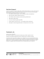
Technical Support
Contact your reseller or supplier for help with possible problems with your CrossCore XA device. In
order to get the best help, you should have access to your CrossCore XA device and be prepared
with the following information before you contact support:
Part number and serial number of the unit, which you find on the brand label
Date of purchase, which is found on the invoice
The conditions and circumstances under which the problem arises
LED indicator flash patterns
CrossCore XA device log files (if possible)
Version number of Code Sourcery –cross compiler used for own binaries
Description of external equipment which is connected to the CrossCore XA
Trademark, etc.
© 2006-2010 CrossControl
All trademarks sighted in this document are the property of their respective owners.
Linux® is the registered trademark of Linus Torvalds in the U.S. and other countries.
CrossControl is not responsible for editing errors, technical errors or for material which has been
omitted in this document. CrossControl is not responsible for unintentional damage or for damage
which occurs as a result of supplying, handling or using of this material. The information in this
handbook is supplied without any guarantees and can change without prior notification.
CrossControl AB
P.O. Box 83 • SE-822 22 Alfta • Sweden
Phone: +46 271 75 76 00•[email protected] • www.crosscontrol.com