1
Introduction
Thank you very much for purchasing TOYO FA Digital Controller ǴGPCsx.
This Programming Manual – Operation is to explain menus, icons etc. of
TDsxEditor as well as its operation. Read this Programming Manual carefully to use it
properly.
Also, read the relevant manuals given in the following table as well.
Description
Manual Number
Contents
ǴGPCsx Series Programming
Manual (Instruction Language)
IGJ057A
It explains the memory, language, system
definition, etc. of the ǴGPCsx Series.
ǴGPCsx Series Programming
Manual (Technique)
IGJ059A
It explains how to configure and prepare
programs.
ǴGPCsx User’s Manual
(Hardware)
IGJ060A
It explains the system configuration,
specifications of hardware of each module,
etc. of the ǴGPCsx Series
Caution
(1)
(2)
(3)
Reprint and reproduction of this manual in part, or in its entirety are
prohibited.
Please note that the contents of this manual are subject to change
without prior notice for improvements.
Regarding the contents of this manual, we have tried to make them as
much complete as possible, but if you have noticed any ambiguities
and/or errors etc., please do not hesitate to contact our sales office
stated at the back of this manual. When you do so, please inform us of
the manual number indicated on the front cover.
1
Safety Notice
Read the “Safety Notice” carefully before using the product, and use it properly.
In this manual, matters that require attention for safety are divided into “Danger”
and “Caution”, which have the following meanings.
Danger
:
Mishandling may cause death or serious injury.
Caution
:
Mishandling may cause intermediate bodily injury, minor injury or damage
to property.
Note that the matter described with
Caution
may cause serious results
depending on the circumstances.
Each of the above describes important contents, which must strictly be observed.
Matters requiring special attention are given below, which are also indicated by the
above marks in the text of this manual.
Danger
•
Emergency stop circuit, interlock circuit etc. must be configured outside of the PC.
Failure to observe this may result in breakage in machines or accidents caused by a fault of the PC.
Caution
•
Change of a program, forced output, start, stop etc. while in operation must be made after making sure
that safety has been secured.
Failure to observe this may cause breakage in machines or an accident as a result of functioning of
machines by misoperation.
2
Revision History
*
Manual number is indicated at the right side of the
bottom of the cover sheet of this manual.
Printed date
* Manual number
Contents of revision
May, 2001
IGJ058A
Printing of the First Edition
(Temporary Edition)
3
Revision History
4
Table of Contents
Preface
Safety Notice
Revision History
Table of Contents
Chapter 1 Preparation and Startup of the System..........................................1-1
1-1 Configuration of the
1-1-1
GPCsx Programming Tool System ..................1-1
Configuration of the ǴGPCsx Programming Tool System ..................... 1-1
1-2 System Requirements ..............................................................................1-2
1-2-1
1-2-2
Hardware Requirements......................................................................... 1-2
Software Requirements .......................................................................... 1-2
1-3 Installation and Uninstallation .................................................................1-3
1-3-1
1-3-2
Method of Installation.............................................................................. 1-3
Uninstallation .......................................................................................... 1-6
Chapter 2 TDsxEditor User Interface ............................................................2-1
2-1 Composition of the Screen and Functions of the TdsxEditor...............2-1
2-1-1
2-1-2
2-1-3
Composition of the Screen of the TDsxEditor ......................................... 2-1
Menu Bar................................................................................................ 2-2
Tool Bar.................................................................................................. 2-2
Chapter 3
Creating a Project..........................................................................3-1
3-1 Project........................................................................................................3-1
3-1-1
3-1-2
3-1-3
Window of the TDsxEditor ...................................................................... 3-1
What Is a Project? .................................................................................. 3-2
What are Task 1 and Task 2 ?................................................................ 3-3
3-1-4
3-1-5
Project in the ǴGPCsx .......................................................................... 3-4
CPU Type ............................................................................................... 3-5
3-2 Editing a Project........................................................................................3-6
3-2-1
3-2-2
3-2-3
Menu Operation of the Project Related Processing................................. 3-6
Pop-up Menu Using the Tree Node ........................................................ 3-8
Editing Operation Related to Subprograms............................................. 3-9
Chapter 4
Editing a Circuit.............................................................................4-1
4-1 Editing the Circuit of a Subprogram or Subroutine ...............................4-1
4-1-1
Each Mode of a Circuit Window.............................................................. 4-1
4-2 Write Mode.................................................................................................4-2
4-2-1
Basic Operation of Write Mode ............................................................... 4-2
5
Table of Contents
4-2-2
4-2-3
4-2-4
4-2-5
4-2-6
4-2-7
4-2-8
How to Insert A-contact........................................................................... 4-6
How to Input a Coil ................................................................................. 4-7
Designating a Timer................................................................................ 4-8
How to Describe a Data Flow.................................................................. 4-9
Constant Representation ...................................................................... 4-10
Function Symbol................................................................................... 4-11
Pop-up menu ........................................................................................ 4-12
4-3 How to Design a Subroutine ..................................................................4-13
4-3-1
4-3-2
Adding a Subroutine ............................................................................. 4-13
Editing a Subroutine ............................................................................. 4-14
4-4 Circuit Listing..........................................................................................4-16
4-4-1
Operation in the Circuit Listing.............................................................. 4-16
4-5 Menu Operation.......................................................................................4-20
4-5-1
4-5-2
4-5-3
“File” Menu ........................................................................................... 4-20
“Edit” Menu........................................................................................... 4-20
“Display” ............................................................................................... 4-23
4-6 On-line Circuit .........................................................................................4-24
4-6-1
4-6-2
4-6-3
Monitor ................................................................................................. 4-24
Monitor Within the Subroutine............................................................... 4-25
Debug................................................................................................... 4-26
Chapter 5
Editing Other Items .......................................................................5-1
5-1 Allocation of the Used Number of Relays and Registers ......................5-1
5-2 Constant Data............................................................................................5-2
5-2-1
5-2-2
5-2-3
Integer data (ki), real number data (kr).................................................... 5-2
On Timer (TS), Off Timer (TR) ................................................................ 5-3
Counter (NP) .......................................................................................... 5-3
5-3 Pattern Data...............................................................................................5-4
5-4 Memory Transfer Definition .....................................................................5-5
5-5 Trace Back.................................................................................................5-6
5-5-1
5-5-2
5-5-3
Trace Back ............................................................................................. 5-6
Trace Back Setting, Window, Register Setting Part ................................ 5-6
Trace Back Setting, Window, Relay Setting Part..................................... 5-7
Chapter 6 System Definition Information .....................................................6-1
6-1 System Definition Information .................................................................6-1
6-2 Type of the System Definition Information .............................................6-1
6-3 Editing the System Configuration Definition..........................................6-2
6
Table of Contents
6-3-1
6-3-2
6-3-3
6-3-4
6-3-5
6-3-6
Tool Bar Button....................................................................................... 6-2
Example of a System Configuration Definition ........................................ 6-2
Example of a Definition When Using a Remote IO.................................. 6-2
Insertion of a Module, Property............................................................... 6-3
Allocation of IO Registers ....................................................................... 6-5
Memory Boundary Definition of CPU Module Parameters....................... 6-6
6-3-7
6-3-8
Handling of Data Memory in the ǴGPCsx System ................................. 6-7
Memory Type.......................................................................................... 6-8
Chapter 7
On-line Function............................................................................7-1
7-1 Relay Display.............................................................................................7-1
7-2 Register Display........................................................................................7-2
7-3 Trend Graph ..............................................................................................7-3
7-3-1
7-3-2
7-3-3
7-3-4
Trend Graph ........................................................................................... 7-3
Trend Menu ............................................................................................ 7-4
Editing the register display items ............................................................ 7-6
Editing the relay display items................................................................. 7-7
Chapter 8
Print ................................................................................................8-1
8-1 Outline of the Print....................................................................................8-1
8-1-1
8-1-2
8-1-3
Screen operation method........................................................................ 8-1
Verification and change of printer settings .............................................. 8-2
Setting of the graph frame printing.......................................................... 8-2
8-2 Individual Printing.....................................................................................8-3
8-2-1
8-2-2
8-2-3
8-2-4
8-2-5
8-2-6
Print [Circuit list]...................................................................................... 8-3
Print [System Definition].......................................................................... 8-4
Print [Parameter]..................................................................................... 8-4
Print [Cross-reference]............................................................................ 8-5
Print [Contact Comment]......................................................................... 8-5
Print [Others] .......................................................................................... 8-5
Chapter 9
Environment Setting, Write Mode Customizing..........................9-1
9-1 Environment Setting .................................................................................9-1
9-1-1
9-1-2
9-1-3
9-1-4
Color Setting........................................................................................... 9-1
Tool Setting ............................................................................................ 9-2
Setting of Communication with the Connected Device............................ 9-3
Setup of the USB Driver.......................................................................... 9-4
9-2 Write Mode Customizing ..........................................................................9-5
7
Preparation and Startup of the System
Chapter 1
Chapter 1
Chapter 1
Preparation and Startup
of the System
1-1 Configuration of the
1-1-1
GPCsx Programming Tool System ...................1-1
Configuration of the ǴGPCsx Programming Tool System...................... 1-1
1-2 System Requirements ..............................................................................1-2
1-2-1
1-2-2
Hardware Requirements......................................................................... 1-2
Software Requirements .......................................................................... 1-2
1-3 Installation and Uninstallation .................................................................1-3
1-3-1
1-3-2
Method of Installation.............................................................................. 1-3
Uninstallation .......................................................................................... 1-6
Preparation and Startup of the System
Chapter 1
Chapter 1
Chapter 1 Preparation and Startup of the System
1-1 Configuration of the
GPCsx Programming Tool System
1-1-1Configuration of the
GPCsx Programming Tool System
Chapter 1
Chapter 1 Preparation and Startup of the System
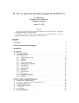
By installing the TDsxEditor (system software) onto a personal computer as
shown in the figure below, it can be used as the programming tool of the ǴGPCsx.
Personal computer
(Windows 98/Me/2000)
TDsxEditor system set
Cable for connection
with a printer
Installation
Printer
Dedicated connection cable
NP4H-CNV (with converter)
NP4H-CAV (without converter)
ǴGPCsx
1-1
Chapter 1
Preparation and Startup of the System
Chapter 1
1-2 System Requirements
1-2-1Hardware Requirements
To operate the TDsxEditor, the following hardware requirements must be
satisfied without fail.
An IBM compatible personal computer or DOS/V personal computer with Intel
Pentium (300 MHz or more recommended).
Windows VGA resolution 800 × 600 dot or more (SVGA resolution 1024 × 768 dot
recommended).
Free space of 100 MB or more in the hard disk.
Memory of 32 MB or more.
A 3.5 inch floppy disk drive (it must be able to read the 1.44 MB format floppy disk)
or CD-ROM drive.
1-2-2Software Requirements
To operate the TDsxEditor, either of the following operating systems is required.
Microsoft Windows 98/Me (Japanese version/English version)
Microsoft Windows 2000 (Japanese version/English version)
Pentium and Windows are registered trademarks.
1-2
Chapter 1 Preparation and Startup of the System
1-3-1Method of Installation
The TDsxEditor software package is delivered in multiple floppy disks. In the
installation disks, installation programs are included, which automatically execute
operation as required for installation and icon registration, etc.
When the installation is carried out by means of a network, copy or/and
installation may not be performed properly, depending on the network environment
and the environment of use.
Installation
(1)
Quit any virus detection software and screen saver programs etc.
(2)
From the “Start” menu of Windows 98/Me, select the “Setting (S)” submenu,
and then select “Control Panel (C)”.
(3)
Left click on the icon of the “Add and Remove Applications” in the “Control
Panel” dialog.
(4)
Left click on the “Install (I)” button.
(5)
Insert the (Disk1) containing installation programs into the floppy disk drive.
(6)
Left click on the “Next (N)>“ button.
(7)
Verify that < A:¥Setup.exe > is displayed on the text box of the “Command
Line (C)” of the installation programs. If it is not displayed, then left click the
“Reference (R)” button to select the drive number, and then select
“Setup.exe”.
(8)
A working box is displayed, showing that “Install Shield Wizard” is being
prepared.
Note)
Although installation programs are prepared using the English
version, when the TDsxEditor is started, it automatically reads out
the language of OS, starting up as the TDsxEditor of the Japanese
version in OS of the Japanese version.
1-3
Chapter 1
1-3 Installation and Uninstallation
Chapter 1
Preparation and Startup of the System
Chapter 1
When the dialog shown on the left is
displayed,
“Next>“ will start the installation.
“Cancel” will stop the installation.
Designate the name of a folder to be
installed.
If the name of the folder is not to be
changed,
left click the “Next>“.
If the name of the folder is to be
changed, then designate the name of
the folder with the “Browse”.
Select the group to be installed.
Do not change it under normal
conditions.
Note) The names of the existing
Japanese application groups
are not displayed correctly due
to the reason of the font, it will
not affect the operation.
1-4
A dialog to verify the installation is
displayed.
If the displayed contents are
acceptable, then “Next>“ will start
copying.
While a message is displayed to show that copying is being made, the copying can
be stopped by left clicking the “Cancel” button.
By left clicking the “Cancel” button, the following dialog is displayed.
“Resume” will continue the installation.
“Exit Setup” will quit the installation.
1-5
Chapter 1
Chapter 1 Preparation and Startup of the System
Chapter 1
Preparation and Startup of the System
Chapter 1
1-3-2Uninstallation
(1)
From the “Start” menu of Windows 98/Me, select the “Setting (S)” submenu,
and then select “Control Panel (C)”.
(2)
Left click on the icon of the “Add and Remove Applications” in the “Control
Panel” dialog.
(3)
Select the TDsxEditor and left click the “Add and Remove (R)”.
In the message box, a question is displayed, asking “Are you sure you want to
completely remove the selected application and all of its components?”
“Yes (Y)” will execute the uninstallation.
“No (N)” will cancel the uninstallation.
1-6
Chapter 2
TDsxEditor User Interface
2-1 Composition of the Screen and Functions of the TDsxEditor ..............2-1
2-1-1
2-1-2
2-1-3
Composition of the Screen of the TDsxEditor ......................................... 2-1
Menu Bar................................................................................................ 2-2
Tool Bar.................................................................................................. 2-2
Chapter 2
Chapter 2 TDsxEditor User Interface
Chapter 2
Chapter 2 TDsxEditor User Interface
Chapter 2 TDsxEditor User Interface
Chapter 2 TDsxEditor User Interface
2-1 Composition of the Screen and Functions of the TDsxEditor
2-1-1Composition of the Screen of the TDsxEditor
Chapter 2
The following screen is displayed when starting TDsxEditor
Menu bar
Tool bar
Project tree
Work space
A project (tree) that was called before or a
default project is displayed.
2-1
Chapter 2 TDsxEditor User Interface
2-1-2Menu Bar
The menu bar execute various functions.
“File”
Commands used for the composition, storage, design and print of the project
are contained.
Chapter 2
“Edit”
Commands used for editing the composition of subprograms within the project
are contained.
“Display”
Commands regarding the display of cross-references within the project and
whether the tool bar is displayed or not are contained.
“On-line”
Commands regarding the downloading and uploading of the project, control of
the ǴGPCsx and various state displays of the ǴGPCsx are contained.
“Tool”
Commands regarding the setting of environments of the tool and the setting of
trace back are contained. The setting of environments of the tool include the
setting of the color of each window, setting of the ǴGPCsx and setting of the
communication with the ǴGPCsx.
“Window”
Commands used for changing the window display are contained.
“Help”
Commands used for calling up the help are contained.
The “File”, “Edit” and “Display” menus vary depending on the items to be
worked on.
2-1-3Tool Bar
Multiple buttons are contained in the Tool bar, and by using these buttons,
functions that are frequently used can be executed comfortably.
2-2
Chapter 3 Creating a Project
Chapter 3
Creating a Project
3-1-1
3-1-2
3-1-3
3-1-4
3-1-5
Window of the TDsxEditor ...................................................................... 3-1
What Is a Project? .................................................................................. 3-2
What are Task 1 and Task 2 ?................................................................ 3-3
Project in the ǴGPCsx........................................................................... 3-4
CPU Type ............................................................................................... 3-5
3-2 Editing a Project........................................................................................3-6
3-2-1
3-2-2
3-2-3
Menu Operation of the Project Related Processing................................. 3-6
Pop-up Menu Using the Tree Node ........................................................ 3-8
Editing Operation Related to Subprograms............................................. 3-9
Chapter 3
3-1 Project........................................................................................................3-1
Chapter 3
Chapter 3 Creating a Project
Chapter 3 Creating a Project
Chapter 3 Creating a Project
3-1 Project
3-1-1Window of the TDsxEditor
The project tree is a window in which items required for editing are displayed.
This tree is composed of groups called “System Definition”, “Task 1”, “Task 2” and
“Subroutine”.
Task 1
It is composed of at least one subprogram.
Each subprogram is executed one by one
from the top.
SPG1 and SPG2 are the names of
subprograms.
Task 2
It is composed of at least one subprogram
(this example shows the case of one
subprogram). Each subprogram is executed
one by one from the top.
SPG3 is the name of the subprogram.
Subroutine
It is composed of subroutines that can be
called from a subprogram. Its setting
contains the arguments of the subroutine and
the range of use of the stack register.
3-1
Chapter 3
System Definition
It is composed by means of the setting of the
GPCsx system.
Chapter 3 Creating a Project
3-1-2What Is a Project?
In a ǴGPCsx application program, there exist system definitions and tasks,
and these exist within 1 CPU.
These, as a whole, are called a project.
Relation between the TDsxEditor and projects in the ǴGPCsx
Open the project
Store the project
Compare
and check
Stored project
Chapter 3
TDsxEditor
Project now
being opened
Upload the project
(connection with the ǴGPCsx)
µGPCsx
Downloaded
project
Download
the project
System Definition
The ǴGPCsx system definitions are contained. The ǴGPCsx system
definitions include the “System Configuration Definition (I/O Allocation)”, “System
Operation Definition”, “CPU Operation Definition” and “Redundancy Definition”.
Task 1 and Task 2
The task determines the processing of programs (execution time schedule) of the
POU. Up to 2 tasks can be executed at one time. However, Task 1 has priority
over Task 2.
In Task 1 and Task 2, there exist multiple subprograms, in which circuits, the
number of relay registers used, constant data and pattern data exist. Task 1 and
Task 2 can independently define separate scan time and execute the ǴGPCsx.
Subroutine
A subroutine is a circuit that can be called from a subprogram. It can be called
from multiple subprograms that exist in Task 1 and Task 2.
3-2
Chapter 3 Creating a Project
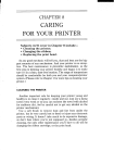
3-1-3What are Task 1 and Task 2 ?
The task determines the processing of subprograms (execution time
schedule). TheǴGPCsx series has 2 types of processing of subprograms: Task 1
and Task 2. 1 and 2 mean the priority of a task and 1 has higher priority.
The scan time should be an integer times the value that has been set in the
SX Bus Tact Time (contained in the System Operation Definition in the System
Definition).
< Operation of the Tasks >
Task 1 Scan Time
Task 2 Scan Time
Chapter 3
Tact
System Task
(Task 0)
Task 1
Task 2
Interruption
: Input Relay, Register Refresh
: Output Relay, Register Refresh
: Operation of the System Task
: Operation of the User Program
3-3
Chapter 3 Creating a Project
3-1-4Project in the GPCsx
Correspondence between theǴGPCsx and the TDsxEditor
Project
CPU Module
System
Definition
System
Definition
Parameter
Intermediate
Code
Code
Conversion
Subprogram
Message
Code
Conversion
Subroutine
Contact
Comment
System Program
Chapter 3
Intermediate
Code
Message
Variable
Initialization
Information
Contact
Comment
User File
Information
Project Definition File
Address Definition File
(To be stored in the
Flash Memory.)
I/O Parameter File
Global Contact Comment
System Program
Processing that performs downloading only.
Processing that performs downloading and uploading.
3-4
Chapter 3 Creating a Project
3-1-5CPU Type
Since the capacity of data memory and program memory varies depending on
the type of CPU module, select them by using the following values as a rough
standard.
TD1PS-32
Number of subprograms: 8 (when the local memory per subprogram is 512 words)
Total number of pages of subprograms: 200 or less
TD1PS-74
Number of subprograms: 32 (when the local memory per subprogram is 512 words)
Total number of pages of subprograms: 400 or less
Number of subprograms: 64 (when the local memory per subprogram is 512 words)
Total number of pages of subprograms: 800 or less
Carry out the design by considering 10 pages per subprogram a rough
standard.
Conversion should be made by counting 1 screen displayed when the circuit
is opened as 1 page.
3-5
Chapter 3
TD1PS-117R
Chapter 3 Creating a Project
3-2 Editing a Project
3-2-1Menu Operation of the Project Related Processing
“File” Menu
“New Project”
It creates a new project. When the program is started for the first time, a
new project is created automatically.
Once a project has been edited, the project is automatically opened from the
next start-up onward.
“Open a Project/Compressed Project”
It opens the existing project or compressed project (the one saved in “Save a
Project by Compression”).
“Overwrite a Project”
Chapter 3
It saves the present project. When working on a new project (when the
topmost item of the project tree is displayed as “Project”), designate a project
name at the time of overwriting.
“Save a Project As …”
It saves a project with a different name.
“Save a Project by Compression”
It saves files in a project as 1 compressed file.
“Setting a Printing Frame”
It edits a frame definition at the time of printing.
“Print”
It prints out the contents of the project.
“Save a Project by Compression” is best suited for making a copy onto a
floppy disk or creating a backup file.
3-6
Chapter 3 Creating a Project
“Compare and Check”
It compares the project now being opened with the stored project. If you wish to
carry out “Compare and Check” on-line (with the project that is downloaded in
theǴGPCsx), then after having performed uploading by means of the “On-line” and
“Connection with theǴGPCsx), select the “Compare and Check”. If any difference
is found, the part having such a difference is displayed.
< Items for which “Compare and Check” are performed >
System Definition (System Composition Definition, System Operation Definition,
CPU Operation Definition)
Scan Time
Memory Transfer Definition
Trace Back Setting
Circuit
Chapter 3
Number of Relays and Registered Used
Constant, Timer and Counter
Pattern Data
Changed items
Points where any
change has been
made
Changed values
Stored values
For example, if a circuit is changed, the circuit number, label name,
symbol and line number that have been changed are displayed.
3-7
Chapter 3 Creating a Project
3-2-2Pop-up Menu Using the Tree Node
When an item other than the name of a subprogram (tree node) has been
selected:
It opens the selected item.
If the sampling of a trace back data is being made,
it opens a trace back display window.
It creates a new subprogram.
Chapter 3
It makes a copy of a subprogram.
It opens the scan time setting of a task of the selected
item.
When an item of a subprogram (tree node) has been selected:
It shows that the
subprogram is an invalid
subprogram.
(Only when being on-line)
Setting valid/invalid of a
subprogram
It can define a subprogram
that is not to be operated
temporarily.
When you left click the
above, the subprogram that
has been made invalid can
now be operated.
When you left click the
above, the subprogram is
made invalid (skipped).
3-8
It opens the circuit of a selected
subprogram.
It executes various on-line
functions of a selected
subprogram.
(Only when being on-line)
It executes the
editing functions of
subprogram.
It displays various
editing windows of
each subprogram.
Chapter 3 Creating a Project
3-2-3Editing Operation Related to Subprograms
“Edit” Menu
“Advance the Order of Operation”
It advances the order of operation of the subprogram that has been selected
in a project tree.
“Retard the Order of Operation”
It retards the order of operation of the subprogram that has been selected in a
project tree.
“Change the Project Name”
It changes the name of a project. If the name of a subprogram is selected
and this command is executed, then the editor turns into the state that allows
you to change the name of a subprogram, and so input any subprogram
name that you desire.
“Create a New Program”
Chapter 3
It creates a new subprogram.
“Delete a Program”
It deletes the selected subprogram.
“Copy a Program”
It makes a copy of a subprogram and generates it as a different subprogram.
When creating a new subprogram or making a copy of a subprogram, the
following dialog box is displayed.
Select the group of the subprogram
that you wish to create or copy
(Task 1, Task 2 or Subroutine).
Input the name of the subprogram.
If you wish to cancel the
operation, click the right
button.
Click the “OK” button to complete
the operation.
3-9
Chapter 3 Creating a Project
“Display”
“Cross-Reference of All Programs”
Of all subprograms and subroutines in a project, a cross-reference is
searched.
Chapter 3
As a method of selection, you can designate the attribute of a data only, as in
“G0”, “mi”, or otherwise you can designate it together with the offset part, as in
“G00000”, “mi00000”.
3-11
Chapter 3 Creating a Project
Example of displaying a cross-reference
It shows the
name of a
data.
It shows the name of a
subprogram in which
the data exists.
Chapter 3
It shows the cross-reference
information.
If you expand the window size,
the number of pieces of
information per line also
increases.
It closes the
cross-reference
window.
Double clicking will display 1 data
name per line.
You can release it by changing the
window size.
Example of display
It stores the content of
the present window
into a CSV file.
Cross-reference information
XXXX – YY (Z)
XXXX: Circuit number
YY:
Line number
Z
L:
Load (contact), S: Store (coil)
I:
Function, subroutine argument (input)
O:
Function, subroutine argument (output)
b:
Unconditional execution subroutine
f:
Unconditional execution function
B:
Conditional execution subroutine
F:
Conditional execution function
The colors of S, I, O can be changed with “Environment Setting” of “Tool”.
3-12
Chapter 3 Creating a Project
“Tool Bar”
It selects a displaying or non-display of each tool bar.
Standard Tool Bar
Common Tool Bar
Ladder Tool Bar
(Effective only at the
time of a circuit editing)
Operation Tool Bar
(Effective only at the
time of a circuit editing)
Chapter 3
Function 1 Tool Bar
(Effective only at the
time of a circuit editing)
Function 2 Tool Bar
(Effective only at the
time of a circuit editing)
Trend Tool Bar
(Effective only in a
Trend Graph)
If you cannot make out what the tool button is used for only by looking at the
pattern of a button, place the mouse pointer on the button. After a short while, the
name of the tool (command name) will be displayed right below the mouse pointer.
3-13
Chapter 3 Creating a Project
“On-line” menu
(Related to download/upload)
“Download”
It downloads all the programs now being opened to the Ǵ GPCsx. While
downloading, the ǴGPCsx is stopped, and it will be reset when the downloading is
over.
“Parameter/Program Download”
It downloads subprograms and subroutines in Task 1 and Task 2 of the programs
now being opened. You can also do this while the ǴGPCsx is in operation. (It
will not download the system definition, Task 1 scan time and Task 2 scan time.)
At this time, it downloads only the subprograms and subroutines that have been
changed, and so the time for downloading can be shortened.
Chapter 3
“System Definition Download”
It downloads the system definition and scan time only. While downloading, the Ǵ
GPCsx is stopped, and it will be reset when the downloading is over.
“Connection with the ǴGPCsx (upload)”
It uploads a project from the ǴGPCsx.
Note)
•
You cannot execute the “Parameter/Program Download” to the Ǵ
GPCsx after the system initialization.
•
Circuit monitor, debugger, relay display, register display, trend graph
can only executed when either of the above 3 is carried out.
(The mode in which these can be executed is called on-line mode.)
3-14
Chapter 3 Creating a Project
(Related to controlling the
GPCsx)
“ GPCsx Reset”
It resets the ǴGPCsx.
“ GPCsx Start”
It starts the ǴGPCsx.
“ GPCsx Stop”
It stops the ǴGPCsx.
“System Initialization”
It clears the user memory in theǴGPCsx. Once executed, the user memory is
cleared and the downloaded applications will be gone, and therefore you should be
very careful when carrying this out.
Chapter 3
“PC Card Driver Download”
It downloads a PC card driver to a module in which a PC card driver exists.
“Compact Flash Storage”
When a CPU module has a built-in unit of compact flash memory, by writing a
project image onto the compact flash memory and inserting it into the CPU module,
the same function as downloading can be realized. (Thus the downloading from
TOOL I/F will not be required.)
3-15
Chapter 3 Creating a Project
(Related to displaying the state of the
“RAS information display of the
GPCsx)
GPCsx”
Selecting the
object of RAS
Area of displaying
detailed information
Chapter 3
Area of displaying
RAS information
The content of the CPU status is displayed.
Switch Information
It displays the state of the Key SW of the CPU module and the CPU number.
Selecting the object of RAS
It selects an object of which RAS information will be displayed.
Renew
It renews the RAS information up to date.
Close
It closes the display of RAS information.
Present RAS, 1 Generation Ago, 2 Generations Ago, 3 Generations Ago
In the case of RAS information that has a history of previous occurrences, RAS in
the past will also be displayed.
Area of displaying RAS information
It displays the RAS information of the object now being selected.
Area of displaying detailed information
In the case of RAS information that has detailed items, detailed information will also
be displayed.
3-16
Chapter 3 Creating a Project
GPCsx Clock Setting
It displays the clock of the ǴGPCsx.
It displays the clock of the
personal computer.
Setting
area
It transmits the value in the
setting area to the ǴGPCsx .
Chapter 3
It transmits the value of the clock of the
personal computer to the GPCsx.
“Resource Information”
It designates tasks.
Task 1 = 1
Task 2 = 2
It displays the starting up
cycle of a task in s.
It displays the execution
time of a task in s.
It displays the used amount of
program memory in the GPCsx.
3-17
Chapter 3 Creating a Project
“Tool” menu
“Environment Setting”
“Help” menu
Project Tree
It displays a project on a tree, whereby you can display the editing window of each
editing item by double clicking.
Work Space
Chapter 3
The editing window of each editing item is located here.
3-18
Chapter 4 Editing a Circuit
Chapter 4
Editing a Circuit
4-1 Editing the Circuit of a Subprogram or Subroutine ...............................4-1
4-1-1
Each Mode of a Circuit Window.............................................................. 4-1
4-2-1
4-2-2
4-2-3
4-2-4
4-2-5
4-2-6
4-2-7
4-2-8
Basic Operation of Write Mode ............................................................... 4-2
How to Insert A-contact........................................................................... 4-6
How to Input a Coil ................................................................................. 4-7
Designating a Timer................................................................................ 4-8
How to Describe a Data Flow.................................................................. 4-9
Constant Representation ...................................................................... 4-10
Function Symbol................................................................................... 4-11
Pop-up menu ........................................................................................ 4-12
4-3 How to Design a Subroutine ..................................................................4-13
4-3-1
4-3-2
Adding a Subroutine ............................................................................. 4-13
Editing a Subroutine ............................................................................. 4-14
4-4 Circuit Listing..........................................................................................4-16
4-4-1
Operation in the Circuit Listing.............................................................. 4-16
4-5 Menu Operation.......................................................................................4-20
4-5-1
4-5-2
4-5-3
“File” Menu ........................................................................................... 4-20
“Edit” Menu........................................................................................... 4-20
“Display” ............................................................................................... 4-23
4-6 On-line Circuit .........................................................................................4-24
4-6-1
4-6-2
4-6-3
Monitor ................................................................................................. 4-24
Monitor Within the Subroutine............................................................... 4-25
Debug................................................................................................... 4-26
Chapter 4
4-2 Write Mode.................................................................................................4-2
Chapter 4
Chapter 4 Editing a Circuit
Chapter 4 Editing a Circuit
Chapter 4 Editing a Circuit
4-1 Editing the Circuit of a Subprogram or Subroutine
4-1-1Each Mode of a Circuit Window
The circuit window has 4 modes.
Read Mode
It is an initial state of mode that appears when the existing circuit is opened.
You can refer to the content of a circuit only. You can move to each of the
modes from here.
Write Mode
It is a mode in which you can edit the circuit.
Monitor
With this mode, the operational state of the Ǵ GPCsx circuit can be
monitored.
Debugger
In addition to the function of the Monitor mode, various debugging functions
can be used.
Circuit Listing
It displays a circuit in the form of a slide given in pages.
Chapter 4
Read Mode Window
The state transfer of each mode is made as follows.
Initial state of a
new circuit
Initial state of
an existing
circuit
Write Mode
Circuit
Listing
On-line Mode only
Debugger
Monitor
Read Mode
4-1
Chapter 4 Editing a Circuit
4-2 Write Mode
4-2-1Basic Operation of Write Mode
Function key arrangement (main menu of the Write Mode)
“Write Completed”
It quits the Write Mode to transfer to the Read Mode.
“Control Line” “Ladder” “Numeral” “Numeric Operation” “Function 1”
“Function 2”
Chapter 4
It switches the menu to each of the symbol insertion menus as shown below.
“Control Line”
“Ladder”
Shift
“Numeral”
Shift
“Numeric
Operation”
Shift
“Function 1”
Shift
“Function 2”
Shift
“Shift”
It switches each function menu.
It can move the position of a function menu to the upper part/lower part of the
window.
Now in the lower part. It will be moved to the upper part.
Now in the upper part. It will be moved to the lower part.
This setting will also be reflected at the next start-up.
4-2
Chapter 4 Editing a Circuit
“Edit”
It switches the menu to the edit menu.
“Main Menu”
With this you can return to the Main Menu of the Write Mode.
“Select”
The cursor position is made to be the starting point of the range of
cutting or copying.
“Cut”
It cuts the range covered with a box.
“Copy”
It copies the range covered with a box.
“Paste”
It paste the cut or copied content.
“Cancel”
A box painting onto the cursor position is cancelled. (Canceling
of the operation of “Select”)
Example of a window in which a box selection has been made
Place the cursor at this position and “Select”.
Chapter 4
Place the cursor at this position and
“Cut” or “Copy”, and the content
will be stored in the paste buffer.
After the “Cut” or “Copy”, the content will be
displayed at the cursor position, and so execute
“Paste” at the position where you wish to paste it.
One “Paste” is carried out, the content of the
paste buffer will not be displayed at the cursor
position any more, but the content of the paste
buffer can still be pasted by pressing “Paste”.
Note that “Select” “Cut” “Copy” “Paste” can also be executed by means of the
Menu Bar or the pop-up menu that appears by right clicking.
4-3
Chapter 4 Editing a Circuit
It inserts 1 line into the cursor position.
“Line Erase”
It erases the line at the cursor position.
“Line Delete”
It deletes the line at the cursor position, and moves the window up
by 1 line.
“Undo”
With this, the operation of “Line Erase” or “Line Delete” can be
cancelled one time only.
“Line Copy”
It copies the line at the cursor position onto the first space line that
is below the cursor line.
Chapter 4
“Line Insert”
4-4
Chapter 4 Editing a Circuit
“Cross”
It displays a cross-reference.
At the time of the Read Mode,
Monitor and Debugger, by clicking the
cross-reference information, a jump to the
said position is executed.
Close the
cross-reference window
Double clicking will display 1 data
name per line. You can release it
by changing the window size.
Example of display
Chapter 4
It stores the
information in a
CSV file.
“10 < > 16”
It switches the mode of the numerical display of an integer data that is used in the
circuit between decimal and hexadecimal.
The present mode is indicated in blue by means of the figure: “10” or “16”.
At the time of a decimal indication
At the time of a hexadecimal indication
4-5
Chapter 4 Editing a Circuit
4-2-2How to Insert A-contact
Move the cursor in a place
you desire to insert.
Select a symbol you desire to insert.
It can also be inserted directly
Chapter 4
Select a relay name by means of a list box.
into the list box.
Then the relay number is input directly. After inputting a contact comment
where necessary, pressing [Enter] key will move the cursor to the next input
position.
Next cursor position
Comment area of the
contact
4-6
Chapter 4 Editing a Circuit
4-2-3How to Input a Coil
After moving the cursor right after the contact symbol,
select a coil symbol, and the following ladder will appear.
Example of inputting an AND circuit
Chapter 4
Under the following status, by inserting a control line symbol,
the deficit part is automatically supplemented.
Example of setting a timer coil
Input timer and counter values below a coil.
Timer and counter values input area
01S = 1 second
4-7
Chapter 4 Editing a Circuit
4-2-4Designating a Timer
Input area of a
timer value
TS0000
10.00S
Input a timer name and input a timer value in a line right below it.
If the timer value is zero, 00.00S is indicated.
If no input is made for the timer value, there is no change in the present set
value.
Input form of a timer value
00H00M ........ sexagesimal
H: hour
00M00S......... sexagesimal
M: minute
00.00S........... decimal
S: second
The setting of a timer value can also be made by means of a constant, timer
or counter window.
When the same timer name is used, if a different value is designated, the one
having a greater Line No. will be effective, and if a different circuit is designated, the
value of a circuit that has newly been edited will be effective.
Chapter 4
Designating a Counter
NP0000
100
Input area of a
counter value
Input a counter name, and input a counter value in a line right under the
name.
If the counter value is zero, 000000 is indicated.
If no input is made for the counter value, there is no change in the present set
value.
Set value area of a counter value
0 - 65535
The setting of a counter value can also be made by means of a parameter
window.
When the same counter name is used, if a different value is designated, the
one having a greater Line No. will be effective, and if a different circuit is designated,
the value of a circuit that has newly been edited will be effective.
4-8
Chapter 4 Editing a Circuit
4-2-5How to Describe a Data Flow
For a constant data, a load instruction should be inserted and a value should
be input just under the name.
Data name
Value
The addition symbol should be inserted at the cross point (+) on the right side
of the load instruction.
Depending on the sequence of
inserting symbols, a supplement of
wiring may be made, in which case
such an operation will not be required.
Chapter 4
After inserting a load instruction below, put wiring.
The data flow is always terminated by a store instruction.
An example of a symbol input accompanied by a data name should be
inserted between the cross points.
4-9
Chapter 4 Editing a Circuit
4-2-6Constant Representation
A numeral should be input in a line just below the symbol.
When the constant value is zero, the indication will be:
Integer type (kiXXXX):
000000
Real number type (krXXXX):
.00000
Example of a constant input
Integer
Real number
123 (decimal)
80 H (hexadecimal)
-123 (decimal) 8005 H (hexadecimal)
123.4 .12345
-123.4 -.2345
For a real number less than 1, the digit of 1 is
omitted.
The setting of a constant value can also be made by means of a parameter
window.
Chapter 4
If a different value is input in a constant having the same constant name, the
one having a greater Line No. will be effective, and if a different circuit is designated,
the value of a circuit that has newly been edited will be effective
4-10
Chapter 4 Editing a Circuit
4-2-7Function Symbol
After a function symbol is inserted, an argument setting window is displayed.
After closing the argument setting window, it can be displayed by double
clicking on the function symbol.
For the parameters of each function, refer to the Programming Manual.
The symbol can also be input by means of a right click.
Chapter 4
By placing the mouse pointer on a function symbol or subroutine symbol, the
parameters of the function or subroutine are displayed.
4-11
Chapter 4 Editing a Circuit
4-2-8Pop-up menu
In the pop-up menu, each symbol insertion function or editing function can
directly be executed by means of a right click of the mouse. Its types are as
follows.
Chapter 4
Main
4-12
Control
Instruction
Logic
Numeral
Numerical
Operation
Numerical
Function
Chapter 4 Editing a Circuit
4-3 How to Design a Subroutine
4-3-1Adding a Subroutine
Create a new program in a project tree to add a subroutine.
Select “add to a subroutine”.
Designate a subroutine name.
Define the number of stack
registers used.
The maximum number that can be
used is displayed in the final
name.
When the number used is
unknown in a subroutine that has
been created beforehand, use this
to search the number used.
Chapter 4
Set the number of parameters.
When the output number is
determined, the input number is
also be determined automatically.
4-13
Chapter 4 Editing a Circuit
4-3-2Editing a Subroutine
The transmission of data with a subroutine shall be carried out by means of
arguments.
An argument means a parameter that is passed on from a calling circuit to a
subroutine program, or an operational result that the circuit receives from the
subroutine.
The number of parameters (number of inputs and outputs) that has been set
in the subroutine setting screen on the preceding page is reflected on the argument
setting screen, and the input and output parts are distinguished by color.
At this point, input on the left side a label name that is passed on to the
subroutine for input, or a label name that is received from the subroutine for output.
For an argument, a relay symbol name can also be set aside from a
numerical register name.
Chapter 4
When a label name is input, the type
of an argument is selected
automatically.
When a constant (ki, kr) is used,
a label name should be input on
the left side, and a value should
be input on the right side.
The input and output
are distinguished by
color.
Example of the
definitions of
arguments
4-14
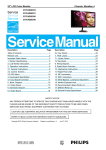
Chapter 4 Editing a Circuit
B
Chapter 4
A
When si0000 (sr0000, SI0000 are the same) is used as a stack register as in
the subroutine shown in the figure above, the data is passed as shown in arrows,
with “A” at the calling side being an input, and “B” being an output.
The flow of the subroutine shown in the figure above
[1]
[2]
[3]
[4]
[5]
In si0000, the value of g00010 at the calling side is loaded, and in si0002, the
value of ki0000(=10) is loaded as set by the argument. These two values
are added in the subroutine.
In si0006, the value calculated in (1) is stored, which will be stored in mi0010
as set by the argument.
The value of mi0001 that has been set by the argument is loaded in si0004,
by which the result of (2) is multiplied.
In si0008, the value calculated by (3) is stored, which will be stored in g00000
as set by the argument.
Finally the value of (4) is loaded in si0000, which will be stored in g00011 at
the calling side.
4-15
Chapter 4 Editing a Circuit
4-4 Circuit Listing
4-4-1Operation in the Circuit Listing
The circuit listing is used for deleting, transferring or copying a circuit in a unit
consisting of pages.
It shows a circuit now being
selected (displayed).
By clicking on it, the displayed
object is switched.
With this, the window returns to
the Read Mode.
(The circuit listing is closed.)
Circuit Transfer
Chapter 4
Circuit Copy
Circuit Delete
Circuit Division
A circuit can be moved by a “drag and drop” operation.
When dragged a mouse pointer as shown on the right side
is displayed.
A circuit can be copied by a “drag and drop” operation.
When dragged a mouse pointer as shown on the right side
is displayed.
It deletes the circuit being selected.
The circuit can also be deleted by the [Delete] key.
It divides a circuit from the circuit being selected as a new
subprogram.
Display while in a “drag
and drop” operation
Mouse menu
Mouse cursor
A place where
the circuit will
be transferred.
The object
selected
4-16
Chapter 4 Editing a Circuit
A copying from another subprogram can also be made.
Chapter 4
After being put into a Circuit Copy state, a circuit can be copied from another
subprogram by a “drag and drop” operation.
4-17
Chapter 4 Editing a Circuit
At the time of Transfer (to move “E” on page 5 to page 2)
1
2
3
4
5
A
B
C
D
E
1
2
3
4
5
A
E
B
C
D
Page number
What is a Transfer?
It is to move a selected page to a designated page by “drag and drop” operation
when there are multiple pages in 1 subprogram. In the above figure, by moving
“E” on page 5 to page 2, the subprogram that was in the order of “A” “B” “C” “D” “E”
changes to the order of “A” “E” “B” “C” “D”.
Chapter 4
At the time of Copy (to copy “E” on page 5 and insert into page 2)
1
2
3
4
5
A
B
C
D
E
1
2
3
4
5
6
A
E
B
C
D
E
Page number
What is a Copy?
It is to copy a selected page in 1 subprogram and insert it to a designated page by
a “drag and drop” operation. In the above figure, by copying “E” on page 5 and
inserting it to page 2, the subprogram that was in the order of “A” “B” “C” “D” “E”
changes to the order of “A” “E” “B” “C” “D” “E”. Unlike a Transfer, the copied page
remains as it is, and the page number is increased by 1 after the page where a
copying and insertion have been made.
4-18
Chapter 4 Editing a Circuit
At the time of a Division (to divide from “C” onward on page 3)
1
2
3
4
5
A
B
C
D
E
1
2
A
B
Page number
Original subprogram
3
4
5
C
D
E
New subprogram
It is to cut a selected page and the other pages thereafter, and to add it to a new
subprogram. In the above figure, if “C” on page 3 is selected, the original program
will be 2 pages: “A” and “B”, and the newly generated program will be 3 pages: “C”,
“D” and “E”.
4-19
Chapter 4
What is a Division?
Chapter 4 Editing a Circuit
4-5 Menu Operation
4-5-1“File” Menu
With this you can move to each of the modes. The present mode is marked
with a check.
The mode that cannot be moved is displayed with a shade.
It shows the present mode.
It closes the circuit window.
4-5-2“Edit” Menu
Each of these performs the cut, copy or
paste of a unit of blocks in a circuit.
Chapter 4
It inserts 1 line at the cursor position.
It deletes 1 line at the cursor
position.
It deletes the line at the cursor position,
and moves the window up by 1 line.
These are valid only in the Write Mode.
4-20
Chapter 4 Editing a Circuit
“Search”
It searches the designated data name.
Character string searched
Input the data name.
Searching direction
Upward:
To search for the data with Circuit
Number .1 ...
Downward:
To search for the data with Circuit
Number +1 ...
“Replace”
Chapter 4
It replaces the designated data name.
Close
It closes the collective conversion window.
Automatic Allocation
It automatically allocates the address of the local memory.
Execute Conversion
Input the character string after replacement and the data name after conversion.
Designate Converted Circuit Range
With this you can designate the range of circuit to which conversion will be carried
out.
4-21
Chapter 4 Editing a Circuit
“Contact Comment”
It displays the setting window of the contact comment.
Designate a relay name in 2 characters (e.g. G0, B0, etc.)
Chapter 4
It searches for the contact comments that are used in subprograms and
displays them in a list.
OK
It incorporates the displayed contents in the contact
comments and then closes the window.
Cancel
It closes the window without using the displayed contents as
the contact comments.
Read CSV File
It reads the contact comments stored in a CSV file.
Store CSV File
It stores the contents on the window in a CSV file.
4-22
Chapter 4 Editing a Circuit
4-5-3“Display”
It changes the displaying
magnification of a circuit.
“Cross-reference”
It searches for the cross-reference information within the circuit
only.
“Cross-references of all programs”
Possible
displaying
magnification
The
magnification
that is displayed
at present is
marked with a
check.
It searches for the cross-references information in all the
subprograms and subroutines in a project.
“Tool Bar”
With this you can select whether each of the tool bars is displayed
or not.
Chapter 4
If you do not know a symbol or data name in a circuit window, then place the
mouse pointer on the symbol or data name, and after a short while the symbol or
data name will be displayed right below the mouse pointer.
4-23
Chapter 4 Editing a Circuit
4-6 On-line Circuit
4-6-1Monitor
Bus: It becomes red while the GPCsx
is in operation.
Chapter 4
With this a transfer to the Monitor Mode is made. When a monitor is
enabled, the button becomes effective. It becomes effective after
“Downloading” or by “Connection with the GPCsx”.
[Read Mode]
With this you can return to the Read Mode.
[Debugger]
With this you can move to the Debugger Mode.
[Cross]
It searches for cross-references.
[10 < > 16]
It switches the decimal display and the hexadecimal display of
integer data.
Display of circuits on a monitor
A Contact:
When the coil is ON, it turns red, and when the coil is OFF, it turns
white (font color).
B Contact:
When the coil is ON, it turns white (font color), and when the coil is
OFF, it turns red.
NOT:
It reverses the result of the logic operation input. (red → NOT →
white (font color), white (font color) → NOT → red)
Coil:
Irrespective of the result of the logic operation on the left side, it is
colored according to the coil data.
Ruled Line:
It represents the result of the logic operation on the left side. The
combined line is colored based on the OR condition.
4-24
Chapter 4 Editing a Circuit
4-6-2Monitor Within the Subroutine
Monitor from the reading side
In the “Read Mode” or “Monitor”, double click on the subroutine symbol and
select “Circuit”. Then the subroutine circuit opens,
and monitoring can be
made by means of the
“Monitor”.
Selection from the project tree
Chapter 4
Select the “Circuit” in the subroutine of a project tree, and select the “Monitor”,
and a list appears that shows the position that can be read, and so, select the
subroutine that you wish to monitor.
When “Monitor” is selected, a subroutine monitor
dialog box appears.
Left clicking “OK” button enables a monitoring.
4-25
Chapter 4 Editing a Circuit
4-6-3Debug
A debugging function can be performed to a symbol at the cursor position.
Upon completion of the debugging, canceling of the changed content can also be
made.
Cursor
Chapter 4
With this you can return to the monitor.
When a change in the circuit has been made, it asks
whether the renewal should be executed.
Yes
Makes the changed content effective.
No
Discards the changed content.
Cancel Cancels the transfer to the monitor.
Data Writing
It writes the
data.
Change
It changes the
data name.
Input the data that you wish to change.
[Enter] confirms it, and [ESC] cancels it.
Input the data that you wish to change.
[Enter] confirms it, and [ESC] cancels it.
Contact ON/OFF
It turns the contact relay ON/OFF.
Contact Change
It changes the contact. (A, a-contact
c-contact)
Addition
It adds a symbol at the cursor position.
B, b-contact,
Input the data that you wish to add.
With this you can select the symbol that you
wish to add.
It deletes a symbol.
It cancels the addition of a symbol.
It executes the addition of a symbol.
4-26
Chapter 4 Editing a Circuit
Debugger function by means of double clicking
Ladder
1
Change the data name (text box display)
I0
00
00
ㆇ ォ ਛ
Change the contact (A, B)
Forced ON/OFF (forced writing)
Data flow
1
ki
00
00
1
00
Change the data name (text box display)
Change the data (forced writing)
B0
00
00
I0
00 00
Change the contact (a, b, c)
ഥ
Forced ON/OFF (forced writing)
4-27
Chapter 4
Change the data name
(text box display)
Chapter 5 Editing Other Items
Chapter 5
Editing Other Items
5-1 Allocation of the Used Number of Relays and Registers ......................5-1
5-2 Constant Data............................................................................................5-2
5-2-1
5-2-2
5-2-3
5-3
5-4
Integer data (ki), real number data (kr).................................................... 5-2
On Timer (TS), Off Timer (TR) ................................................................ 5-3
Counter (NP) .......................................................................................... 5-3
Pattern Data ........................................................................................... 5-4
Memory Transfer Definition..................................................................... 5-5
5-5 Trace Back.................................................................................................5-6
Trace Back ............................................................................................. 5-6
Trace Back Setting, Window, Register Setting Part ................................ 5-6
Trace Back Setting, Window, Relay Setting Part..................................... 5-7
Chapter 5
5-5-1
5-5-2
5-5-3
Chapter 5
Chapter 5 Editing Other Items
Chapter 5 Editing Other Items
Chapter 5 Editing Other Items
5-1 Allocation of the Used Number of Relays and Registers
It sets the number of local memory used in a subprogram.
The setting should be made within a range not exceeding the remaining
number of words.
By defining the numbers of integer patterns and real number patterns, it is
possible to define the number of points.
When using these, the number to
be set should be within a range of
2 - 200.
Pattern output
value
Chapter 5
The number of points
means the number
indicated with an arrow in
the figure on the right.
Number of
points
5-1
Chapter 5 Editing Other Items
5-2 Constant Data
It defines the integer constant data (ki), real number constant data (kr), on
timer value (TS), off timer value (TR) and counter value (NP).
Items to be edited can be selected by means of the tabs on the upper side.
5-2-1Integer data (ki), real number data (kr)
Items to be edited can be
selected by means of the
tabs on the upper side.
With “Close”, the constant
data will be closed, and
parameters will be reflected.
Matters to be noted when setting the constant value
When the constant value is zero, the indication will be:
Integer type (kixxxx):
000000
Real number type (krxxxx): .00000
Example of a constant input
Chapter 5
Integer
123 (decimal)
80 H (hexadecimal)
-123 (decimal)
8005 H (hexadecimal)
Real number 123.4 .12345
-123.4
-.2345
In order to increase the number of digits that can be input, the zero of 0.xxxx
is omitted.
5-2
Chapter 5 Editing Other Items
5-2-2On Timer (TS), Off Timer (TR)
Input form of a timer value
00H00M ........ sexagesimal
H: hour
00M00S......... sexagesimal
M: minute
00.00S........... decimal
S: second
5-2-3Counter (NP)
Setting range of the counter value
Chapter 5
0 - 65535
5-3
Chapter 5 Editing Other Items
5-3 Pattern Data
Pattern name
Either of the following should
be selected.
pi0000 - pi0004,
pr0000 - pr0004
Pattern preview
A graphic display should be
made in accordance with the P,
Q of pattern data.
Here a display and editing of
the pattern data:
P, Q is carried out.
OK
It renews the pattern data and closes the window.
Cancel
It makes the changed content invalid and closes the window.
CSV Read
It inputs the pattern data that was read from a CSV file into the pattern data of P, Q.
When a dialog box of “Open a File” is displayed, select the file name.
Chapter 5
CSV Store
It stores the pattern data of P, Q in a CSV file.
When a dialog box of “Store a File” is displayed, select the file name.
5-4
Chapter 5 Editing Other Items
5-4 Memory Transfer Definition
In the memory transfer definition, a definition of data transfer can be made
prior to the execution of an operation of a subprogram in the task as well as after
the execution.
A transfer between the global memory, between separate subprograms and
between subroutine stack registers can be carried out.
A memory transfer is processed prior to and after the execution of an
operation of a subprogram in the task.
Chapter 5
Output refresh
Memory transfer
(after the execution of an operation)
Subprogram 2
Subprogram 1
Memory transfer
(prior to the execution of an operation)
Input refresh
The execution schedule shall be as follows.
5-5
Chapter 5 Editing Other Items
5-5 Trace Back
5-5-1Trace Back
A trace back can be used when you wish to investigate only a part of
continuous data, in which either of the bits in the trigger register is turned ON, and
only 100 data prior to and after the timing of the turning ON are retained, thereby
reading the retained sample data values later on, and enabling you to analyze the
data.
First, in the (CPU module-parameter memory boundary definition), the setting
of the number of trace back surfaces and the number of samples should be made.
Next, the setting of the trigger register and the sample data should be made. The
setting can be made to each of the Task 1 and Task 2. (The number of samples
shall be the total of both.)
5-5-2Trace Back Setting, Window, Register Setting Part
Name:
Any character string can be input.
Sample Data:
The setting of a register name to be sampled should be made.
Program name:
The setting of a program name which uses the register to be
sampled.
Trigger register:
When either of the bits of this value becomes OFF → ON, a
trigger is effected.
Sampling interval:
Values to be skipped when scanning should be defined.
Example) 1 sample per 1=1 scan, 1 sample per 5=5 scan
In relation to the triggered time, the number of points of
samples after the said time should be defined.
Chapter 5
Trigger point:
In the case of a register, the maximum number of allowable settings of
sample data and trigger registers is 16.
This is because only 1 sample data can be set in relation to 1 trigger register.
Hence, as shown in the figure above, the third sample data can be set to the third
trigger register as well.
5-6
Chapter 5 Editing Other Items
Example of a trace back
Trigger point
99
Trigger point
50
Trigger point
2
Scan
5-5-3Trace Back Setting, Window, Relay Setting Part
In the case of a relay, the number of settings of sample data is up to 16, while
the number of settings of trigger registers is only 1. This is because up to 16
sample data can be set in relation to 1 trigger register. Hence, as shown in the
figure above, from the second onward, the setting of “Trigger register” - “Trigger
point” can not be set.
The definition of trace back memory cannot be made unless the setting of trace
back memory is made by means of the system definition - CPU - Parameter
memory boundary definition.
While in the operation without batteries, the trace back data will be wiped out when
the power is turned off.
5-7
Chapter 5
“Name” - “Trigger point” are the same as in the register.
Chapter 6 System Definition Information
Chapter 6
System Definition
Information
6-1 System Definition Information .................................................................6-1
6-2 Type of the System Definition Information .............................................6-1
6-3 Editing the System Configuration Definition..........................................6-2
Tool Bar Button....................................................................................... 6-2
Example of a System Configuration Definition ........................................ 6-2
Example of a Definition When Using a Remote IO.................................. 6-2
Insertion of a Module, Property............................................................... 6-3
Allocation of IO Registers ....................................................................... 6-5
Memory Boundary Definition of CPU Module Parameters....................... 6-6
Handling of Data Memory in the ǴGPCsx System ................................. 6-7
Memory Type.......................................................................................... 6-8
Chapter 6
6-3-1
6-3-2
6-3-3
6-3-4
6-3-5
6-3-6
6-3-7
6-3-8
Chapter 6
Chapter 6 System Definition Information
Chapter 6 System Definition Information
Chapter 6 System Definition Information
6-1 System Definition Information
In the system definition, a composition of the overall system, a setting of
operations and a setting of operations of individual modules are carried out that are
required for constructing a system by means of the ǴGPCsx and putting it in
operation.
To edit it, double click on the tree node, or right click on it to choose “Open”.
6-2 Type of the System Definition Information
System Definition Information
The system configuration, CPU memory definition and IO parameter are defined.
System Operation Definition
The SX bus tact time, composition check waiting time and CPU initialization method
are defined.
CPU Operation Definition
Chapter 6
The processor number, WDT time, setting of operation at the time of powering on,
and setting of operation without batteries are defined.
6-1
Chapter 6 System Definition Information
6-3 Editing the System Configuration Definition
6-3-1Tool Bar Button
It displays the property of a module.
It inserts a module at the designated position.
It deletes a module at the designated position.
It exchanges the position of the designated module
with the module placed above.
It divides the unit at the designated position.
When being on-line, it reads the system configuration
information from the ǴGPCsx. The conditions can
only be read on condition that the ǴGPCsx is not in
a serious failure.
6-3-2Example of a System Configuration Definition
Chapter 6
6-3-3Example of a Definition When Using a Remote IO
In the remote IO (JPCN-1 “OPCN-1”, DeviceNet), the slave module below the
master module is inserted.
6-2
Chapter 6 System Definition Information
6-3-4Insertion of a Module, Property
When a module is inserted, the property window is displayed, then the
module classification and module name should be selected.
This should be
selected first.
It should be selected after the
module classification has been
selected. By changing the module
classification, items that can be
selected are changed.
To define the CPU memory and IO parameters, click the parameter button on
the property of the module.
Only the parameter button of a module having parameters becomes effective.
It is used when a module does not actually exist although it is defined in the
system configuration definition. Also, in the screen of the configuration definition,
a red mark is displayed on the mark of the module.
The CPU module cannot be made to be unmounted.
When the remote IO master module is made to be unmounted, all the slave
modules must be made to be unmounted.
6-3
Chapter 6
What is unmounted?
Chapter 6 System Definition Information
Addition
It will be added at this position.
To insert into a lower position.
Chapter 6
It will be inserted at this
position.
6-4
Chapter 6 System Definition Information
6-3-5Allocation of IO Registers
The allocation of IO registers in the ǴGPCsx system is made by using a
32-bit boundary in hexadecimal representation. It also includes the input and
output data of the remote IO (OPCN-1 and DeviceNet).
Example)
TD1S-22
AC power supply 35 W
TD1PS-74
High performance CPU74
NP1L-FL1 FL-NET
NP1X1606-W DC input
16 pieces
NP1Y32T09P1
sync output 32 pieces
NP1Y64T09P1
sync output 64 pieces
NP1L-JP1 OPCN-1 master
OPCN-1 I/F for RSH64 VF64
SDS64 inverter for synchronous
control
KPB878 diffusion type
Tubo controller
Address
Allocation of IO Registers
IO registers are not allocated.
0 (h)
1 (h)
2 (h)
3 (h)
4 (h)
5 (h)
6 (h)
7 (h)
8 (h)
9 (h) 14 (h)
15 (h) 1E (h)
1F (h) 2A (h)
2B (h) 34 (h)
35 (h) 3E (h)
3F (h) 4A (h)
i00000 1 w
These are handled as unused areas.
o00002 2 w
o00004 4 w
1 w is occupied in the remote IO master.
i00009 12 w
o00015 10 w
i0001F 12 w
o0002B 10 w
i00035 10 w
o0003F 10 w
Chapter 6
System Configuration
TD1BS-13 13-slot base
6-5
Chapter 6 System Definition Information
6-3-6Memory Boundary Definition of CPU Module Parameters
[2]
[1]
Here the setting of memory used within a project is carried out.
Global memory
This is the memory that any subprogram or subroutine can gain access to. It
has a relay, an integer register and a real number register.
Local memory
It is the memory that is effective within a subprogram only. It has registers of
differential, latch, timer, counter, etc., in addition to a relay, an integer register
and a real number register.
[1]
Set the number of subprograms that exist in Tasks 1 & 2.
[2]
Set the number to be used within 1 subprogram.
Retain memory
It is the memory that retains its contents even when power is shut off. It has
a relay, an integer register and a real number register.
Function subroutine instance memory
It is the memory that is secured internally every time a function or subroutine
is called. The present number of words used is displayed after downloading
them. It depends on the number of functions and subroutines used, and so
when the set value is exceeded, it can be increased later on. The user
cannot use it.
Chapter 6
Trace back memory
It is the memory that is used in the trace back. The user cannot use it.
System FB memory
It is a memory area used in the system FB. The user cannot use it.
6-6
Chapter 6 System Definition Information
6-3-7Handling of Data Memory in the
GPCsx System
The data memory of ǴGPCsx application programs can be divided into 3
groups, global memory, local memory and stack register.
Global memory
It is the memory that all subprograms can gain access to.
Flash memory G0 (relay), g0 (register: integer), gr (register: real number)
Retain memory RI (relay), ri (register: integer), rr (register: real number)
Input area I0 (relay), i0 (register: integer),
Output area 00 (relay), o0 (register: integer),
Local memory
It is the data memory that is effective within a subprogram only. Included in
its types are flash memory, latch differential, timer, counter, constant and
memory for pattern functions.
B00000 -, b00000 LS0000 -, LR0000 -, LC0000 US0000 -, UC0000 -, DS0000 -, DC0000 -,
TS0000 -, TD0000 -, tn0000 -, TR0000 -, TC0000 -,
tf0000 -,
NP
Stack register
It is the local memory that is effective within a subroutine only.
SI0000 si0000 -
Chapter 6
sr0000 -
6-7
Chapter 6 System Definition Information
6-3-8Memory Type
Global memory
G00000 g00000 gr0000 - etc.
Local memory
B00000 -, b00000 mi0000 -, mr0000 ki0000 -, kr0000 - etc.
Stack register
SI0000 si0000 sr0000 -
Relations among subprograms, subroutines and data memory
Global memory
Read and write
enabled
Access prohibited
Subprogram
Subprogram
Local memory
Sb
Local memory
Sb
Sb
Handing over by
arguments
Subroutine
Stack
register
Stack
register
Stack
register
Chapter 6
Except the stack registers
that have been set in the
argument setting screen,
these can only be used
within the subroutine.
6-8
Chapter 6 System Definition Information
Parameters of each IO module
Definition of operation modes of directly connected I/O
Setting of digital filter constants
It sets the input delay time of a digital input module.
No setting, 100 s, 1 ms, 3 ms, 3/10 ms, 10 ms, 30 ms and 100 ms
Flags showing that the setting values of digital filter constants are valid
When the above setting of digital filter constants is used, this should be made
“valid”.
The setting can be made in the following modules.
NP1X1606-W, NP1X3206-W, NP1X6406-W, NP1X3202-W, NP1X3206-A,
Chapter 6
NP1W1606T, NP1W1606U, NP1W3206T, NP1W3206U,
6-9
Chapter 6 System Definition Information
Definition of the HOLD of directly connected I/O
Definition of the directly connected HOLD
“HOLD mode”
It is a function used when there is an abnormality and the CPU module has
come to a stop, if you wish to make it retain the state of output immediately
before the occurrence of the abnormality, or if you wish to make it retain the
state of output immediately before the stop of CPU while CPU is stopped.
“Reset mode”
When an output is turned OFF, the above function is made invalid.
The setting can be made for the following modules.
NP1Y08T0902, NP1Y16T09P6, NP1Y32T09P1, NP1Y64T09P1,
NP1Y08U0902, NP1Y16U09P6, NP1Y32U09P1, NP1Y64U09P1,
NP1Y08S, NP1Y06S, NP1Y08R-04, NP1Y16R-08, NP1W1606T,
NP1W1606U, NP1W3206T, NP1W3206U
System D0 definition
Chapter 6
1 bit per configuration can be defined that will output the state of operation of
the system without reference to applications. It is ON when the entire
system operates normally, and turned OFF when there is an abnormality in
the system. The bit that can be set is the 0-th bit of the output only.
6-10
Chapter 6 System Definition Information
Mixed module definition
For a mixed module, the definition of operation modes of directly connected
I/O and the definition of the HOLD of directly connected I/O should be made.
The setting can be made for the following modules.
Chapter 6
NP1W1606T, NP1W1606U, NP1W3206T, NP1W3206U
6-11
Chapter 6 System Definition Information
JPCN-1 master module parameter
The JPCN-1 master module parameter is set against the “NP1L-JP1”.
Module classification-IO master
(1)
Definition of response time
In the JPCN-1 communication, response time from the receiving of frames to
the start of transmitting in the master (switching time from receiving to
transmitting) should be set.
Select the response time out of the following.
Rate
Remarks
200 s
In compliance with JEM-F3008
Initial setting
{
150 s
100 s
Maximum rate
About 50 s.
Note) If there is any slave equipment on which no specific value is
designated as response time, select 200 s.
Definition of inherent operations of the JPCN-1 slave
It becomes the station number of the JPCN-1
slave.
It is automatically assigned based on the
number of IO or configuration.
Note) Its setting cannot be made.
Chapter 6
Set the number of IO of the JPCN-1 slave.
The register and relay numbers are determined
automatically.
6-12
Chapter 6 System Definition Information
JPCN-1 slave – parameter
(1)
Definition of communication monitoring time
It sets the communication monitoring time against each slave station.
The monitoring time should be set within the following range.
•
Default:
1500 ms
•
Set value:
1 - 65534 (× 10 ms)
Note) Resetting when the communication monitoring has an abnormality should be
made by repowering the JPCN-1 master side. Then the output at the time of
an abnormality is put in the “HOLD state”, but the output will be OFF when
resetting is made, to which attention should be paid.
(2)
StypeM definition
It sets the specifications of the slave.
At the time of the initial setting service, the master checks the composition of
each slave based on these data.
Symbol
Description
Content
DI
Input data
DO
Output data
DR
DW
ST
Read data
Write data
Whether there is I/O
type designation or
not
Whether there is I/O
arrangement
information or not
When a slave having input signals is used
(DI module, etc.)
When a slave having output signals is used
(DO module, etc.)
When a slave that outputs data is used
When a slave that inputs data is used
SA
It is set when there is a mixed slave of input and
output within 1 module.
* In this module, it is not used.
Note that the setting of the StypeM varies depending on the slave, and its details
should be checked with each slave.
The setting should be made with the following modules.
NP1L-RJ1, RSH64, SDS64, KPB878 and TPC-193
When other slave equipment than the above types is connected, the “NP1L-JCP
(JPCN-1 capsule) should be used.
6-13
Chapter 6
*
By checking this signal, the above settings
(DI, DO, DR, DW) become valid.
Chapter 6 System Definition Information
Definition of master operations of the DeviceNet
NP1L-DN1 (module classification - IO master)
Definition of the individual output HOLD station
Of the output nodes, MAC ID of the node that requires the setting of HOLD
should be selected by left clicking.
Chapter 6
Note) It may not be effective for a node of which output HOLD setting is made by a
hardware switch. Check the specifications of the slave node used.
6-14
Chapter 6 System Definition Information
Polling/bit strobe transmission interval (EPR)
It is the expected_packet_rate attribute value that is used in the slave node of
which scan method is set at the polling or the bit strobe. The value as obtained by
multiplying this attribute value by 4 becomes the time-out value of the slave node,
and when the slave node does not receive data even if the time-out value is
exceeded, the node is dropped form the DeviceNet. When this value is set at 0,
the setting will be as per the table below, depending on the number of slave node
units connected and the transmission rate.
Inter-scan delay time (ISD)
The master node will, after having transmitted I/O data to the slave node, wait
the response of the slave node for a period of time as set herein.
When this value is set at 0, the setting will be as per the table below,
depending on the number of slave node units connected and the transmission rate.
The value of EPR and ISD when the set value is 0
Number of slave node
units connected
Transmission rate
(bps)
EPR (ms)
ISD (ms)
1 - 21 units
125
250
500
125
250
500
125
250
500
30
26
20
64
50
38
94
76
56
40
36
26
86
66
50
126
100
76
22 - 42 units
43 - 63 units
Number of times of skipping the scan cycle of the background polling station
Chapter 6
It sets how many times the scan cycle is skipped by the slave node that has
been set to carry out the background polling. The number of times can be set up
to 10000. When it is set at 0, the polling operation shall be the same as that of
making scan polling every time.
6-15
Chapter 6 System Definition Information
DeviceNet slave - parameter
It becomes the DeviceNet slave MAC ID.
It is assigned automatically depending on the
number of IO or composition.
Note) Its setting cannot be made.
It sets the number of IO of the DeviceNet
slave.
Register and relay numbers are determined
automatically.
MAC ID
The same value as the remote station number of module information (MAC ID)
should be set.
Definition of the scan type
It sets the DeviceNet scan type. Select it out of the following to meet the slave
node specifications and make the setting.
Polling, bit strobe, change of state, and cyclic.
Definition of the polling type
The polling type should be selected out of the following.
Polling at every scan, background polling
Change of state/cyclic transmission interval
Chapter 6
It sets the change of state/cyclic transmission interval. When the scan type is set
at the change of state or cyclic, if the transmission interval is set at 0, then the data
transmission from the said node will not be carried out.
It should be set against the following modules.
NP1L-DCP, DNET64
The “NP1L-DCP (DeviceNet capsule)” sets other modules than the above types.
6-16
Chapter 6 System Definition Information
Definition of operations of the FL-net module
The definition of operations of the FL-net module should be set as the parameters
of “NP1L-FL1”.
Definition of operations
Machine type code definition Sub-classification
It sets the type of CPU used. In the ǴGPCsx series, there is “high performance
CPU” only.
Writing network parameters (P)
Writing block data (B)
Start/stop command (R)
It sets the writing of data from the FL-net network (other nodes), and
permission/prohibition of start/stop.
IP address (I) HH
IP address (I) LH
It sets the IP address. The default values are: 192 (HH), 168 (HL) and 250 (LH).
By ***, the host address part will have the value of the node number setting at the
front of the module.
6-17
Chapter 6
IP address (I) HL
Chapter 6 System Definition Information
Token monitoring time (T)
Unit:
ms
It sets the monitoring time to monitor the transmitting time of the cyclic transmission
using the common memory area. The default value is 50 ms, and the setting
range is 1 - 255 ms. When communication with the -GPCH (TPC-196) is carried
out, it should be “50” or more.
Minimum frame interval (F)
Unit:
× 100 s
The time from the receiving by the node in question of a token that the other node
dispatched up to the sending out of a frame by the node in question is called a
frame interval. Wherein, the time required for waiting until the sending out of a
frame by each node to the minimum extent is called a minimum frame interval.
The default value is 10 × 100 s, and the setting range is 0 - 50. The unit is 100 s.
If it is set at “0”, then the operation is made at a maximum rate. When
communication with the -GPCH (TPC-196) is carried out, it should be “50”.
Whether or not there are node name/equipment name
When the node name below is designated, this should be “valid”.
Node name/equipment name
With this a node name is designated. The maximum number of characters is 10 in
1-byte characters.
Area setting
It sets the transmitting area of the node in question at the cyclic data transfer.
Each area setting
When the transmitting area of the node in question is used, this should be set to
“valid”.
Automatic setting of the foremost address (offset)
It calculates the foremost address by means of the node number.
Area 1 (A) foremost address
It designates the foremost address of the transmitting area of the node in question
in area 1.
Area 1 (A) word size
It sets the number of words of the node in question in area 1.
Chapter 6
Area 2 (R) foremost address
It designates the foremost address of the transmitting area of the node in question
in area 2.
Area 2 (R) word size
It sets the number of words of the node in question in area 2.
6-18
Chapter 6 System Definition Information
About the automatic setting of the foremost address (offset)
By designating the foremost station number, it reads the node number of the FL-net
module that was mounted at the time of downloading, thereby automatically
calculating the “area 1 (A) foremost address”, “area 2 (R) foremost address” and
the foremost address of the node after the “foremost station number”. When it is
set, the settings of the area 1 (A) foremost address and area 2 (R) foremost
address as shown below have different meanings.
Note) This shall only apply when the CPU module is in normal conditions, or after the
initialization of the system.
FL-net cyclic data area
Example of setting it as “foremost station number 3”
Area 1 (A) or area 2 (R)
foremost address
Node number 1 transmitting area
Node number 2 transmitting area
Transmitting area of node number 3
and thereafter
(Station number of the mounted module Foremost part of the station number)
× Word size is the foremost address.
Area 1 (A) foremost address
It designates the foremost address of area 1 on which you wish to make automatic
calculations.
Area 1 (A) word size
It designates the number of transmitting words of the node in question that are
common in area 1 after the “foremost part of the station number N”.
Area 2 (R) foremost address
It designates the foremost address of area 2 on which you wish to make automatic
calculations.
Area 2 (R) word size
It designates the number of transmitting words of the node in question that are
common in area 2 after the “foremost part of the station number N”.
(System definition information) When downloading, since the following message
box is displayed, if the setting is acceptable, click “Yes (Y)” to go on downloading.
Clicking “No (N)” stops the downloading.
Chapter 6
Example of setting) When the node number to which
downloading is made is 2
Area 1 foremost address: 0 + (2 - 1) × 32 = 32
Area 2 foremost address: 0 + (2 - 1) × 64 = 64
6-19
Chapter 6 System Definition Information
Area 1, 2 transmitting bank switching operation CPU definition (S)
It sets the refreshing method (synchronous/asynchronous) of the transmitting area
of the node in question within the common memory, and sets the CPU that sends
out switching instruction at the time of the synchronous method.
All areas
receiving bank switching operation CPU definition (S)
It sets the refreshing method (synchronous/asynchronous) of the receiving area of
the node in question within the common memory, and sets the CPU that sends out
switching instruction at the time of the synchronous method.
Composition register definition 1, composition register definition 2
Chapter 6
It registers the node number of all the nodes that are connected to the FL-net,
including the node number of the node in question. However, a setting at 0 or 255
is prohibited.
6-20
Chapter 6 System Definition Information
System operation definition
(1)
SX bus tact time
The SX bus tact time is a cycle for exchanging data with modules connected
with the SX bus (input and output module, etc.)
The setting value should be set from 0.5 ms to 10.0 ms at intervals of 0.5 ms.
After 1.0 ms it should be set at intervals of 1 ms, as in “0.5 ms”, “1.0 ms”, “2.0
ms”.
The default value is 1.0 ms.
Note 1) The 0.5 ms tact cycle can be executed under the conditions of the single
CPU in the case of high performance CPU, less than 256 directly connected
I/Os, with “no” remote I/O or communication module.
Note 2) In products of which CPU firmware version is V34 or older, or V3A - V3Z,
the setting can be made up to 20 ms at intervals of 1 ms.
(2)
Composition checking waiting time
The CPU module, when the system is powered on, carries out the
initialization of the CPU module. When the initialization has been completed,
it starts the composition checking of modules that are on 1 configuration.
The time required for the completion of this composition checking is set by
means of the “composition checking waiting time”.
Method of initialization
When the system is powered on, the initialization of the CPU module is
carried out, and whether or not at this time the memory diagnosis inside the
CPU module is to be made should be set by this. When the memory
diagnosis is to be made, the initialization time of the CPU module is about 4.5
s, and when the memory diagnosis is not to be made, it is about 2.5 s.
Note 1) In the memory diagnosis, a device read/write check is carried out.
Chapter 6
(3)
6-21
Chapter 6 System Definition Information
Setting of the tact cycle of CPU
In the SX bus, the data exchange between the CPU module and the I/O modules is
carried out by synchronizing with the tact cycle. A rough calculation formula for
calculating the time of scanning for each tact cycle is given below, and basically the
tact cycle of the SX bus depends on the system configuration. Also, in a system
that requires the task cycle at the tact cycle, it depends on the number of
processing steps of an application program. The exact time of execution needs to
be checked by the actual machines.
< System configuration that depends on the tact cycle >
Number of I/Os
Number of CPUs
Number of remote I/O master units
Number of communication modules
(1)
Rough calculation formula for the tact cycle that depends on the system
configuration
Tact cycle T (
[1]
)
When 1 CPU + directly connected I/Os: T = Tb
[base time that depends on the number of directly connected I/Os (Tb)]
Number of directly
connected I/Os (pieces)
Base time Tb (s)
0
32
128
256
512 1024 2048 3072 4096 6144 8192
418
504
507
510
556
695 1042 1388 1520 1711 1911
The time given above shows the case of the input:output ratio of I/O =
1:1, and as the output increases, the time increases, and as the output
decreases, it decreases, with the range of such fluctuations being about
± 20%.
Note 1) However, the 0.5 ms tact cycle can be executed under the conditions
of the single CPU, less than 256 directly connected I/Os, with “no”
communication module.
Chapter 6
Note 2) The tact cycle can be selected from 0.5, 1, 2, 3, ……, 18, 19, 20 ms,
and the value obtained by rounding up a figure in the above table
should be selected.
6-22
Chapter 6 System Definition Information
[2]
In the case of multi CPU: [number of CPUs: n]
T = Tb + 210 n
(number of directly connected I/Os: 2048 or less)
T = Tb + 200 n + 190
(when the number of directly connected I/Os exceeds 2048)
[3]
In the case of a single CPU + remote I/O:
[number of remote I/O master units: m]
T = Tb + 250 m + 430
(number of directly connected I/Os: 2048 or less)
T = Tb + 280 m + 730
(when the number of directly connected I/Os exceeds 2048)
[4]
In the case of multi CPU + remote I/O:
[number of CPUs: n, number of remote I/O master units: m]
T = Tb + 340 n + 200 m + 400
(number of directly connected I/Os: 2048 or less)
T = Tb + 405 n + 260 m + 340
(when the number of directly connected I/Os exceeds 2048)
[5]
In the case of ([1]) CPU + directly connected I/O with communication
modules being added: [number of communication modules: p]
T = Tb + 40 p + 250
In the case of ([2] - [4]) with communication modules being added:
[number of communication modules: p]
T = (time obtained by [2] - [4]) + 85 p
[without a remote master module]
T = (time obtained by [2] - [4]) + 128 p
[with a remote master module]
Note 3) The remote I/O is calculated as 2048 pieces/line.
Chapter 6
[6]
6-23
Chapter 6 System Definition Information
Appendix 2 - 2
(2)
Calculation formula of the operational performance in the case of executing
the scanning at a tact cycle
Operation time =
[tact cycle time] - [SBM overhead time (200 s)] [I/O refresh time] - [POU control time]
•
I/O refresh time = 2n + m + 60 ) s
[n: number of I/O modules, m: number of total words of I/O]
•
POU control time = PG control time + user FB control time + user FCT
control time
= 4a + 6b + 7c ) s
[a: number of PGs, b: number of calls of user FB, c: number of calls of
user FCT]
Note 1) POU is short for program composition unit.
Note 2) PG denotes each task of a program. If system task × 2, task 1 and
task 2, then a = 4.
Note 3) User FB denotes a subprogram or subroutine.
Note 4) User FCT denotes a function or system function.
Operation time =
[tact cycle time] - (2n + m + 60)
- (4a + 6b + 7c) s
Number of program steps = [operation time/execution time of 1 instruction/
1024] k steps
Number of program steps = [operation time/20.48] k steps
[in the case of execution time of 1 instruction
= 20 ns]
= [operation time/61.44] k steps
[in the case of execution time of 1 instruction
= 60 ns]
Note 5) For the execution time of each type of instruction, refer to the
processing speed given in the Programming Manual.
Chapter 6
Note 6) The instruction execution time varies depending on the access time
of the memory allocated to variables under operation. Hence,
depending on the number of variables that an instruction has access
to, the increased access time given below should be added to the
execution time of instruction. The access time of memory shall be
as follows.
[1]
I/O memory: reference time (20 ns)
[2]
Other memory: 40 ns to be added
[3]
Other CPU memory via the processor bus: 3 s
(FI, fi, fr, EI, ei, er and w0 - w7 fall under this category.)
6-24
Chapter 6 System Definition Information
Example of time calculation
[1]
In the case of a single CPU
Scan time
(tact time)
System configuration
POU control time
(number of PG/FB/FCT)
Program executable time
(converted to 20 ns step)
0.5 ms
CPU ... 1 unit
(use of communication modules
prohibited)
Directly connected I/O: 256 pieces
68 s
(4/4/4)
124 s
(6 k step)
1 ms
CPU ... 1 unit
Directly connected I/O:
1024 pieces
136 s
(8/8/8)
412 s
(20 k step)
CPU ... 1 unit
Directly connected I/O:
2048 pieces
480 s
(16/32/32)
876 s
(42 k step)
CPU ... 1 unit
Directly connected I/O:
2048 pieces
480 s
(16/32/32)
876 s
(42 k step)
CPU ... 1 unit
Remote I/O ... 2 units:
Directly connected I/O:
4096 pieces
2048 pieces
480 s
(16/32/32)
492 s
(24 k step)
POU control time
(number of PG/FB/FCT)
Program executable time
(converted to 20 ns step)
480 s
(16/32/32)
2492 s
(484 k step = 121 k × 4)
480 s
(16/32/32)
2620 s
(508 k step = 127 k × 4)
2 ms
[2]
In the case of a multi CPU
Scan time
(tact time)
System configuration
CPU ... 4 unit
Remote I/O ... 2 units:
Directly connected I/O:
4 ms
4096 pieces
2048 pieces
CPU ... 4 unit
Remote I/O ... 2 units:
4096 pieces
Directly connected I/O: 1024 pieces
Communication ... 2 units
Chapter 6
(3)
6-25
Chapter 6 System Definition Information
(4)
Rough calculation formula for calculating the tact time in the 1:1 warm
standby redundancy system
In the 1:1 warm standby redundancy system, the tact time increases to the
extent that the additional equivalent data transfer is required between the
operating/standby CPUs as compared with the ordinary multi CPU. The
rough calculation formula is given below. In the formula below, redundancy
tact time 1 (TR1) or redundancy tact time 2 (TR2), whichever greater should be
adopted.
Redundancy tact time 1 (TR1) [s]
TR1 =
ordinary tact time+596 × N + 430
(number of directly connected I/Os: 2048 or less)
TR1 =
ordinary tact time+626 × N + 730
(when the number of directly connected I/Os exceeds 2048)
N:
number of redundancy CPU pairs
Note) The ordinary tact time is the tact time obtained by the rough calculation formula
of (1). Then, the number of CPU units is calculated by using the number of
redundancy CPU pairs.
Redundancy tact time 2 (TR1) [s]
•
TR2 = (I/O refresh time) + TDMA + TCPY + 200 [s]
I/O refresh time: (2n + m + 60) [s]
[n: number of I/O modules, m: number of total I/O words]
•
TDMA = [number of SX bus modules other than CPU] + (number of
CPU modules) × 2
+ (number of remote master modules × 55)+(number of all directly
connected/remote I/O words) + 512] × 0.5 [s]
•
TCPY = (number of words of equivalent variables of the standard
memory, retain memory) × 0.3
Chapter 6
+ (number of words of user FB memory, retain memory) × 0.35 + 10 [s]
6-26
Chapter 6 System Definition Information
CPU operation definition
There are 3 setting items in the CPU operation definition: watch dog timer,
explanation of operation at the time of powering on, and operation without batteries.
(1)
Watch dog timer
The setting of a watch dog timer can be made at 1 ms up to 4095 ms.
default value is 4095 ms.
(2)
The
Designation of operation at the time of powering on
It designates the operation of the CPU module at the time of powering on,
when the key switch at the front panel of the CPU module is in the position of
RUN or TERM.
The operation of the CPU module by this setting and by the position of the
key switch at the front panel of the CPU module is as follows.
The default value is “RUN: operation/TERM: operation”.
< Operation of CPU by the position of the key switch >
Operation
RUN:
TERM:
RUN:
TERM:
RUN:
TERM:
operation/
operation
operation/
state of the previous time
stop/
stop
RUN
TERM
Operation
Operation
Operation
State of the previous time Note)
Stop
Stop
Note) The state of the previous time means the state of CPU before the power of the
system is shut off. If the CPU was in operation, the state becomes in operation, and
if it was stopped, the state becomes being stopped.
If the setting is made to the operation without batteries, the CPU module carries out
initialization of the memory every time when the operation of CPU is started, prior to
the start of operation. Also, no backup error of data is detected.
The default value is “not” to carry out the operation without batteries.
6-27
Chapter 6
Setting of the system definition
Chapter 7
Chapter 7 On-line Function
Chapter 7
On-line Function
7-1 Relay Display.............................................................................................7-1
7-2 Register Display........................................................................................7-2
7-3 Trend Graph ..............................................................................................7-3
7-3-1
7-3-2
7-3-3
7-3-4
Trend Graph ........................................................................................... 7-3
Trend Menu ............................................................................................ 7-4
Editing the register display items ............................................................ 7-6
Editing the relay display items................................................................. 7-7
Chapter 7
Chapter 7 On-line Function
Chapter 7 On-line Function
Chapter 7
Chapter 7 On-line Function
7-1 Relay Display
Input the relay names in the input area (the leftmost grid).
When inputting, by pressing the [Enter] key, the cursor moves to the next line,
and the relay name to which +16 has been added is set automatically.
Since it is displayed in a unit of 16 pieces, the setting of the final digit cannot
be made for the relay name. If you wish to change the relay name, press the [F2]
key.
shows the state of relay on.
shows the state of relay off.
Note) When the displayed data increase, the refreshing speed of the display
becomes slower.
Menu bar
“File”
“Relay display completed”
It closes the relay display.
“Edit”
“Delete 1 line in the relay display”
It deletes 1 line in the relay display. It makes the setting of the cursor line
invalid, and moves up the lines after the said 1 line. If it is the last line, only
a clearing of the setting shall be carried out.
“Contact ON/OFF”
It turns the contact ON/OFF. While it is marked with a check, it can be
turned ON/OFF by clicking on the applicable data.
shows that the relay to change from OFF to ON is being selected.
shows that the relay to change from ON to OFF is being selected.
7-1
Chapter 7 On-line Function
Chapter 7
7-2 Register Display
Input the register name in the input area (the leftmost grid). When inputting,
by pressing the [Enter] key, the cursor moves to the next line, and the register
name to which +8 has been added is set automatically, but you can change it freely.
As for the data display, 8 data is displayed per line. If you wish to change the
register name, press the [F2] key.
Note) When the displayed data increase, the refreshing speed of the display becomes
slower.
Menu bar
“File”
“Hexadecimal display”
It switches between the hexadecimal display and the decimal display. The
state of being marked with a check is the hexadecimal display state.
“Register display completed”
It closes the register display.
“Edit”
“Delete 1 line in the register display”
It deletes 1 line in the register display. It makes the setting of the cursor line
invalid, and moves up the lines after the said 1 line. If it is the last line, only
a clearing of the setting shall be carried out.
“Data change”
While it is marked with a check, it changes the register value at the position
on which right clicking has been made, and sends it out to the ǴGPCsx.
7-2
Chapter 7 On-line Function
7-3-1Trend Graph
When the trend graph is selected by right clicking on the tool bar or project
tree, a trend window as shown in the figure below is opened, and the selected
register and the trend graph of relays are displayed on a real time basis.
It shows the register name
being selected.
It shows the relay name
being selected.
The time axis is represented
by the lapse of time that
assumes the closest sample
time to be 0 second.
By right clicking on the mouse in the trend window, the menu as shown in the
figure below is displayed.
It stops the trend graph temporarily.
It draws ruled lines in the trend graph.
It changes the register to be sampled.
It changes the relay to be sampled.
It quits the trend graph.
7-3
Chapter 7
7-3 Trend Graph
Chapter 7 On-line Function
Chapter 7
7-3-2Trend Menu
With the trend menu (tool bar), the following functions can be used.
“File” menu
“Temporary stop”
It stops the trend graph temporarily.
“Print”
It prints the trend graph.
“Store to a BMP file”
It stores the trend graph into a bit map file.
“Store to a CSV file”
It stores the sample data sampled by the trend graph into a CSV file.
When the following dialog box is displayed after the file name is designated,
set the storage parameters and store them.
With this, the number of data stored is
designated.
It shows the number of data sampled.
With this, the points to be stored out of the sampled data are
designated. The data position from the entire sampled data
is shown on the bar graph.
“Continuous CSV file storage”
While the trend graph is in operation, CSV files are generated continuously for
each number of samples designated.
File name
(Designated file name) 1.CSV, (Designated file name) 2.CSV ...
“Quit the trend graph”
It quits the trend graph.
7-4
Chapter 7 On-line Function
“Edit”
Chapter 7
“Editing the register display items”
“Editing the relay display items”
“Editing the sampling time”
“Display”
“Displaying the ruled lines”
Tool bar explanation
It sets the sampling intervals. The setting range is 100 ms - 10000 ms (10
s).
7-5
Chapter 7 On-line Function
Chapter 7
7-3-3Editing the register display items
It changes the settings of the register sampled by the trend graph.
With this, the color
of graphs can be
changed.
Designate the
attribute of the
register name
(2 characters).
Designate the
offset part of the
register.
Designate the
minimum and
maximum values of the
graph displayed.
It makes the
setting valid and
closes the dialog.
7-6
It makes the
setting invalid and
closes the dialog.
Sampling can be
made valid
temporarily.
It applies the
settings without
closing the dialog.
Chapter 7 On-line Function
7-3-4Editing the relay display items
Chapter 7
It changes the settings of the relay sampled by the trend graph.
With this, the color
of graphs is
changed.
Designate the
attribute of the
relay name
(2 characters).
Designate the
offset part of the
relay.
It makes the
setting valid and
closes the dialog.
It makes the
setting invalid and
closes the dialog.
Sampling can be
made valid
temporarily.
It applies the
settings without
closing the dialog.
7-7
Chapter 8
Print
8-1 Outline of the Print....................................................................................8-1
8-1-1
8-1-2
8-1-3
Screen operation method........................................................................ 8-1
Verification and change of printer settings .............................................. 8-2
Setting of the graph frame printing.......................................................... 8-2
8-2 Individual Printing.....................................................................................8-3
8-2-1
8-2-2
8-2-3
8-2-4
8-2-5
8-2-6
Print [Circuit list]...................................................................................... 8-3
Print [System Definition].......................................................................... 8-4
Print [Parameter]..................................................................................... 8-4
Print [Cross-reference]............................................................................ 8-5
Print [Contact Comment]......................................................................... 8-5
Print [Others] .......................................................................................... 8-5
Chapter 8
Chapter 8 Print
Chapter 8
Chapter 8 Print
Chapter 8 Print
Chapter 8 Print
8-1 Outline of the Print
The printing functions of the TDsxEditor are shown below.
Chapter 8
Printing of a circuit list
Printing of a system definition
Printing of parameters
Printing of cross-references
Printing of contact comments
Printing of others
8-1-1Screen operation method
By selecting [Print (P)] in the [File (F)] menu of the TDsxEditor, the following
detailed printing screen is displayed.
By pressing [Do not print], the selected item is made
invalid, and then it cannot be selected. Also, [Print
execution [Enter]] button will not be able to be
pressed.
By pressing [Print], the contents can be
selected. Also, [Print execution [Enter]]
button will then be able to be pressed.
With this, it is
selected whether or
not a frame should
be added when
printing each item.
With this, printing is made by making each item
valid.
It can be pressed when either one of the items is
set at [Print].
It closes each item
set by making it
invalid.
It displays the
“Printer setting”
dialog.
8-1
Chapter 8 Print
8-1-2Verification and change of printer settings
With this, the standard printer to be used is selected.
< Procedure of selecting the printer >
By pressing [Print setting] on the print setting screen, the [Setting of printer]
dialog is displayed.
♦
[Print name (N)] With this the printer that is used in the list box is selected.
♦
After having set “Paper”, “Direction of printing”, “Property” and others where
necessary, [OK ] button should be left clicked.
Chapter 8
♦
8-1-3Setting of the graph frame printing
With this, selection is made as to whether each item as has been selected by
pressing [Print] (circuit list, system definition, parameter, cross-reference, contact
comment, and others (project tree, memory transfer definition and trace back) is
printed with a graph frame or not.
♦
By pressing [Print graph frame], the following item is displayed.
♦
Do not print graph frame When this is selected, the graph frame is not
printed when printing.
♦
Default
8-2
When this is selected, the graph frame is printed,
which is the default setting.
Chapter 8 Print
8-2 Individual Printing
You can print items by selecting the desired items such as [Circuit list],
[System definition], etc.
8-2-1Print [Circuit list]
♦
With this, the selected program circuit is printed.
Chapter 8
Each subprogram of the task 1,
task 2, subroutine that have
been prepared in a project is
displayed.
When printing a circuit, the following functions are added.
♦
♦
♦
Option
[Comment]
When this is selected, the circuit list is printed
as it is.
[Cross-reference]
When this is selected, the cross-reference of
the coil that has been stored under the
contact is printed.
[Space]
Nothing is printed below the contact.
Multiple printing of the circuit
[Circuit × 1 [horizontal print]
1 circuit is printed by making the direction of
print horizontal.
[Circuit × 2 [vertical print]
2 circuits are printed by making the direction
of print vertical.
Printing of integer data
[Decimal number printing]
The integer data within the circuit is printed in
decimal numbers.
[Hexadecimal number printing] The integer data within the circuit is printed in
hexadecimal numbers.
Note)
Only horizontal printing can be made when a graph frame is printed.
8-3
Chapter 8 Print
8-2-2Print [System Definition]
♦
It prints the composition of the entire system, operation setting, etc.
Chapter 8
In the default state, this remains
checked. If it is left as it is,
parameters of each module are also
printed when printing
[System configuration definition
(I/O allocation)].
♦
System configuration definition (I/O allocation)
It prints the content of the system configuration tree that has been set by the
system definition.
♦
System operation definition
It prints parameters that have been set by the system operation definition.
♦
CPU operation definition
It prints parameters that have been set by the CPU operation definition.
8-2-3Print [Parameter]
♦
It prints the number of programs used and values of parameters.
Each subprogram of the task 1,
task 2, subroutine that have been
prepared in a project is displayed.
Number of parameters used
It prints the number of parameters that are used within a program.
Values of parameters
It prints the values of parameters (ki, kr, TS, TD, NP) that are used within a
program.
8-4
Chapter 8 Print
8-2-4Print [Cross-reference]
♦
It prints the cross-references of the selected programs.
Chapter 8
Each subprogram of the task 1, task 2,
subroutine that have been prepared in
a project is displayed.
8-2-5Print [Contact Comment]
♦
It prints the contact comment of the selected programs.
Each subprogram of the task 1, task 2,
subroutine that have been prepared in
a project is displayed.
8-2-6Print [Others]
♦
It prints the selected items.
< Project tree >
It prints the project tree.
< Memory transfer definition > It prints the transfer definitions of tasks 1 & 2.
< Trace back setting >
It prints the contents of the trace back
settings of tasks 1 & 2.
8-5
Chapter 9 Environment Setting, Write Mode
Customizing
Chapter 9
Environment Setting,
Write Mode Customizing
9-1-1
9-1-2
9-1-3
9-1-4
Color Setting........................................................................................... 9-1
Tool Setting ............................................................................................ 9-2
Setting of Communication with the Connected Device............................ 9-3
Setup of the USB Driver.......................................................................... 9-4
9-2 Write Mode Customizing ..........................................................................9-5
Chapter 9
9-1 Environment Setting .................................................................................9-1
Chapter 9
Chapter 9 Environment Setting, Write Mode Customizing
Chapter 9 Environment Setting, Write Mode
Customizing
Chapter 9 Environment Setting, Write Mode Customizing
9-1 Environment Setting
9-1-1Color Setting
Chapter 9
In the color setting, the color of the screen can be changed. By right clicking
the item to be changed, a dialog box for the color setting is displayed, at which the
desired color should be selected.
9-1
Chapter 9 Environment Setting, Write Mode Customizing
9-1-2Tool Setting
Chapter 9
In the tool setting, various settings of the TDsxEditor can be made.
9-2
Chapter 9 Environment Setting, Write Mode
Customizing
9-1-3Setting of Communication with the Connected Device
It determines the means to connect the ǴGPCsx and the TDsxEditor.
COM port
This should be designated when the COM port (serial port) provided on a PC
is to be used.
Ethernet
By inserting an Ethernet card into the PC card module of the ǴGPCsx, the
TDsxEditor can be used via Ethernet. When making its settings, designate
the IP address and port No. of the ǴGPCsx (PC card module).
By inserting a modem card into the PC card module of the ǴGPCsx, the
TDsxEditor can be used via the telephone line. When making its settings,
designate the telephone number of the line to the ǴGPCsx is connected (PC
card module) and the dialing method of the line connected to the modem
used and the PC (personal computer).
USB
The USB connector of R type CPU (TD1PS-117R) and the PC should be
connected with USB.
In order to use USB, you should set up the USB driver.
9-3
Chapter 9
Modem
Chapter 9 Environment Setting, Write Mode Customizing
9-1-4Setup of the USB Driver
In order to connect the TDsxEditor with the ǴGPCsx, you should set up the
USB driver.
When the ǴGPCsx is connected to the PC (personal computer), the driver
install screen of Windows is displayed, whereupon select the folder as shown below
in the OS.
The folder in which the TDsxEditor
has been installed
Chapter 9
The folder in which the USB driver is
stored
“2 k”
Driver for Windows 2000.
“98 Me”
Driver for Windows 98/Me.
9-4
Chapter 9 Environment Setting, Write Mode
Customizing
9-2 Write Mode Customizing
In the write mode customizing, a shortcut key (accelerator key) in the write
mode of the circuit window can be designated.
After having selected the “write mode function” for which you wish to set a
shortcut key, select a shortcut key by means of the “Shortcut key: setting”.
Select the “write mode function” for
which you wish to set a shortcut key.
Chapter 9
It shows the shortcut key that is set
at present.
With this, you can select a shortcut
key.
9-5