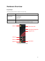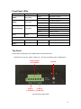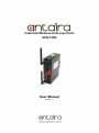
1
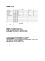
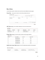
Front Panel LEDs
LED
Color
PWR1
Green/Red
PWR2
Green/Red
WLAN Strength
Diag
Green/Red
Green
Status
Description
Green
DC power 1 active
Red
DC power 1 fail/non active
Green
DC power 2 active
Red
DC power 2 fail/non active
Red
LED 1 < 25%
Green
LED 2 < 50%
Green
LED 3 < 75%
Green
LED 4 ≤ 100%
Blinking
Unit not ready/Boot sequence
Off
Unit ready
10/100Base-T(X) Fast Ethernet ports
ETH 1
Yellow
On
Port link up at 10Mbps
ETH 2
Green
On
Port link up at 100Mbps
Top Panel
The top panel components of the APN-310N are showed as below:
*Terminal block includes: PWR1, PWR2 (12 ~ 48V DC) and Relay output (1A@24VDC)
Relay Output
(1A @ 24VDC
Ground
Power 2
Power 1
(12-48VDC) (12-48VDC)
Top panel of the APN-310N
11