1
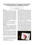
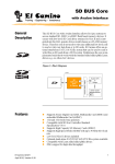
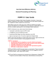
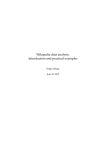
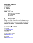
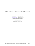
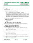
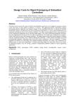
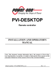
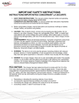
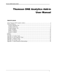
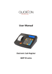
EXOSKELETON CONTROL OF A PROGRAMMABLE ROBOT
ARM USING FIELD-PROGRAMMABLE GATE ARRAYS
Rhyan Andrade, Donnie Bañez, and Carlos Oppus
Ateneo de Manila University
[email protected], [email protected], [email protected]
Abstract - The core objective of this project is the development of an exoskeleton controller for a prototype robotic arm,
which is stand-alone, portable, programmable, and easy to maintain and use. The design and implementation utilizes a
field-programmable gate array (FPGA) to meet this objective. At present, exoskeleton controllers of robotic manipulators
are usually bulky, stationary and usually dependent on a personal computer or mainframe. The product of this project
can become a basis for future exoskeleton controller designs, where it can make a significant impact on almost everyone
especially in industry and research. Such designs will be invaluable in automated factory processes, construction, toxic
waste handling such as maybe needed at the Philippine Nuclear Research Institute and hospitals handling radioactive
materials, operations in a vacuum environment, honey-bee culturing and even deep sea or space exploration.
Furthermore, the design can bring a complex technology to a level that everyone can comprehend, and can promise a full
utilization of such. Based on existing designs and technologies studied, a lightweight, portable and easy-to-wear
exoskeleton controller was constructed. This exoskeleton coupled with the use of an FPGA to serve as the system's main
processor will make the controller of a robotic arm easier to move, handle, understand, use, and maintain. With the whole
setup completed, the programmable robotic arm controlled by an exoskeleton controller is yet another important
achievement in the field of robotics.
1. INTRODUCTION
Robot control varies greatly in the manner it is implemented
and the type of material it uses to drive the structures. There are
three drive methods or techniques to cause movements in the
joints of robots. These are the hydraulic drive, pneumatic drive
and the electric drive. All three have their own advantages. For
instance, hydraulic drive is preferred for high speed and heavy
load requirements, but electric drive is the best choice for
assembly operations that require precision and cleanliness. In
today's industry settings, there are still a lot of hydraulic and
pneumatic-driven robot technologies, but the electric-driven
power systems tend to dominate and emerge above the other two
mainly because of its easy maintenance, stability and
flexibility[1]. Under the electric-driven systems, still a lot of
methods are utilized. There are robotic manipulators controlled
by entering directly the displacements of the end-effectors into
the system from a computer's console[2]. These designs are used
in high precision applications. There are also programmable
systems wherein a series of movements are stored in a RAM to
be played in a later time. Still there are designs whose controllers
resemble human body parts and are used by wearing the
controller and performing the actual movements the user wishes
to implement in the robotic manipulators. These controllers are
also referred to as exoskeleton controllers, because they resemble
an exoskeleton harness worn by users to control the end effectors.
2. STATEMENT OF THE PROBLEM
There are already many existing robot exoskeleton
controllers. However most of these are dependent on a computer
terminal or mainframe to operate. Although the computer is a
powerful computational device, physically, a personal computer
still takes too much space and is heavy to move from one location
to another. This makes the robotic controllers attached to them
inherit their properties of bulkiness and virtual immobility[3].
Moreover, such designs also require the users to first understand
their programs to properly operate the system. A user may need
an additional background on how to operate a computer and
interface the controller with it. As such, a non-technical person
may find it hard to understand how such a device may work.
2.1. Objectives
To answer these problems and at the same time provide an
advanced feature, the project aims to develop an exoskeleton
control for a prototype robotic arm that is:
1) stand-alone, meaning it should be independent on any
computer to perform its tasks;
2) portable, meaning it should be small and light enough
to be carried anywhere and plugged into any power
source;
3) programmable, meaning it should provide an option
for the users to record a series of actions and be able to
playback or perform the action repeatedly. This feature
allows the transformation of the exoskeleton controller
to a preprogrammed controller; and
4) user-friendly, meaning it should be comfortable enough
to wear, easy to use, understand, and maintain.
2.2. Methodology
The main hardware description language used to design
the whole project was Verilog with Quartus and Verilogger Pro
as the main software for editing, debugging and uploading.
Before the actual code for the project was written, tests were run
to check whether the input/output ports of the FPGA give the
correct signals to the external circuits, and accept signals from
the latter. Small Verilog codes corresponding to small circuits
were written to check in isolation the external input and output
ports of the FPGA.
With the I/O ports properly configured and verified, the
code for the main controller program was developed and tested
for functionality through software simulation. The programming
capability was added last, and subjected to the same simulation
tests.
Since all the hardware and software modules were already
tested in isolation, the next step to be taken was to commission
everything and test for functionality as a whole. The software
was loaded into the FPGA and the external circuits were
connected. Tests were conducted to verify the system's
functionality as a whole and necessary observations were taken.
2.3. Significance of the Study
The exoskeleton controller design would provide a blueprint
for the design of a commercial robot arm controller to be used in
practical day-to-day applications. The product of this project can
become a basis for future exoskeleton controller designs, where it
can make a significant impact on almost everyone especially in
industry and research. Such designs will be invaluable in
automated factory processes, construction, toxic waste handling
such as maybe needed at the Philippine Nuclear Research
Institute and hospitals handling radioactive materials, operations
in a vacuum environment, honey-bee culturing and even deep sea
or space exploration. These applications require the exposure of a
person’s limb to a hazardous environment, thus increasing the
risk involved in the operations. Using exoskeleton controllers to
control robotic arms situated in the hazardous environments can
decrease, and even eliminate the danger involved in the exposure.
Furthermore, the design can bring a complex technology to a
level that everyone can comprehend, and can promise a full
utilization of such. Since motors driving a robot arm can have a
torque greater than what a person can physically exert, portable
robot arms can be carried anywhere by anyone and may be used
as force amplifiers in doing heavy and loaded tasks such as lifting
appliances off the floor, cleaning hard-to-reach places, handling
hazardous materials, and a lot more. Moreover, due to the nature
of exoskeleton control, the user does not have to compute for
displacements to be entered into the system nor learn about a
complicated software or hardware control program. He or she
will only need to wear the controller and then simulate directly
what they want the arm to do. Taking a step further, the
programmable capabilities of the exoskeleton design would allow
a lot of users to free themselves from routinary and patterned
tasks and let the robot arm do the repetitive work. All that is
needed is to program the sequence of tasks in the arm and then
leave it to do the series of tasks on its own.
user wearing the controller is doing, even with a few degrees of
difference.
The speed of the response of the robot arm to the
movements of the exoskeleton controller also falls outside the
project's scope. The robotic arm utilized in this project moves
with a relatively slow speed (but its torque is considerable strong)
and an attempt to increase its speed would either endanger the
life of the DC motors or sacrifice the resolution and range of the
control. What is important for this project is that the robotic
manipulator follows the movements of the controller in its fullest
range, even at the cost of maintaining the arm's natural speed.
Another part of the project's limitation is the absence of a
starting position for the robotic arm upon initialization. The
design provided means of manually initializing the arm to a start
position, either through using the exoskeleton controller itself or
the manual controller. When the recording mode is switched on,
the user can always manage to bring the robotic arm back to its
original position after doing its task. So upon playback, the robot
would still perform the same action in a cyclic manner.
3. HARDWARE
The hardware mainly consists of five major parts: (1) the
exoskeleton controller, (2) the sensor circuit, (3) the fieldprogrammable gate array or FPGA, (4) the arm controller relays,
and (5) the robotic arm itself. In the normal mode of operation,
the exoskeleton controller provides the input into the system by
means of sensors located near the joints of the human arm. The
input analog signals coming from these sensors are then fed into
the sensor circuit to be converted into digital signals. Afterwards,
the digital signals are entered into the FPGA. Based on the
magnitude of the signals, the FPGA would send out the
appropriate output signals to control the robotic arm. They would
pass through the relays, which would either switch on or off the
DC motors in the robotic arm trainer. The DC motors are the
ones capable of moving the robotic arm in the system.
Exoskeleton
Controller
ADC Sensor
Circuit
FPGA
2.4. Scope and Limitations
The whole scope of the work deals with the interfacing of
the sensors (50-KO potentiometers) from the exoskeleton
controller to the robot arm, through a field programmable gate
array. The main highlight would then be the external interface of
the FPGA board to external circuits. Concerns on achieving an
almost zero percent error between the exact angular displacement
of the exoskeleton controller and that of the robot arm lies
outside the project's scope. For the set goals of the project, it is
enough for the robot arm to follow the general sense of what the
Relay
Circuit
ROBOT
ARM
Figure 1. Block diagram of the entire hardware setup
The exoskeleton controller serves as one of the input
terminals of the system. It translates the motion of the human arm
into a series of voltage signals that are in turn, interpreted by the
field-programmable gate array (FPGA). After processing, the
FPGA will send out the appropriate signals for the robotic arm to
emulate. In this way, the robotic arm moves according to the
motion of the exoskeleton controller.
The exoskeleton controller is a device with six built-in
potentiometers, serving as sensors, to detect the full motion of the
human arm-as shown in Figure 4.1. Rotating the knob of the
potentiometer (by the movement of the human arm), in effect,
varies the resistance in the device. Thus, with a constant current
driving the sensor, the voltage is also varied. By Ohm's Law,
which is V = IR, the voltage would vary directly proportional to
the change of resistance. These voltage signals are then fed into
the sensor circuit.
Shoulder Rais e
The FPGA is a technology for making integrated circuits.
What sets it apart from other chip technologies is that it is field
programmable. One can design and implement any chip and
would not need any external manufacturer. This entails less risk
since one can afford to make a mistake and not lose several
weeks just to have another chip made. In that case, just modify
the design, re-program the chip, load it into memory, and run the
system.
12-Bit
Data Bus
Exoskeleton Controller
HC 245
12-Bit Bi-Directional
Data Bus
3.1
Gripper
MAXIM 198
ADC
Elbow Raise
Wrist Rotate
LM
358
LM
358
LM
358
LM
358
LM
358
Shoulder Rotate
Figure 2. The exoskeleton with the corresponding controls for
the robotic arm
Each of these potentiometers represents an axis of motion
provided by the human joints. The entire human arm, from the
shoulder to the hand, has four joints. There is a ball-and-socket
configuration at the shoulder to accommodate the shoulder raise
and shoulder rotate motion. The elbow joint provides the elbow
bend. Wrist bend and wrist rotate are made by the wrist joint
while the human hand provides the gripping motion. For the
exoskeleton to imitate the human arm, there should be a sensor
for each of axes of motion.
3.2. Sensor Circuit
This circuit serves as the input interface between the
exoskeleton controller and the FPGA. Designed to obtain
readings from the five potentiometers attached to the
exoskeleton, the sensor circuit mainly converts the analog input
signals into digital signals. The MAX198 ADC chip makes this
conversion possible. Other components within the circuit only
serve to support this conversion. Furthermore, this circuit also
enables the FPGA to communicate with the ADC and vice versa.
3.3. Field-Programmable Gate Array
SENSORS
Figure 3. Block diagram depicting the various connections
inside the sensor circuit
Since it defines the nature of the project, the FPGA has
become the heart and brain of the system. Inputs are read from
the sensors and are then converted but they must pass through the
FPGA for processing. All other circuits serve as wired
peripherals for proper communication and translation of signals
from the exoskeleton controller to the FPGA and then to the
robotic arm. Based on the inputs, the code within the FPGA will
determine the appropriate response for the robotic arm to do. It is
the one that decides which motors of the robotic arm should run
and for how long. The FPGA can also be configured to
implement different modes of operation. Because of it, the
system can also be made programmable, meaning the user can
record a series of actions through the exoskeleton and the robotic
arm can do it repetitively and indefinitely. Finally, the FPGA is
the reason for making the system portable and independent from
a computer. It no longer needs an external processor to decode
the signals; the instructions are already encoded within the
miniature programmable integrated circuit[4].
3.4. Relay Circuit
In contrast with the sensor circuit, the relay circuit serve as the
output interface between the FPGA and the robotic arm. After
decoding the inputs and determining the proper response, the
FPGA will now send signals to activate certain relays, which act
as switches for the DC motors within the robotic arm. To switch
on a motor to move to a particular direction, the FPGA needs
only to send logic high to its corresponding output port. There are
ten (10) motors controlled by the FPGA, two for each of the
motors of the robot arm. Each motor is controlled by a single bit
from the FPGA through its port P2. This single bit is connected
to the input of an opto-isolator network (made up of 4N25 optoisolator, 2N3907 transistor and several resistors to protect the
FPGA from feedback signals coming from the output), which is
in turn connected to the transistor driver circuit at the other end.
The driver circuit (made up of 2n2222 transistor and several
transistors) turns on an electromechanical relay which eventually
switches a particular motor in the robot arm. This opto-isolator
and driver circuit network is constructed for each of the ten
motors.
As an alternative input device, the manual controller that
came along with the robot arm (its original controller) was also
interfaced with the relay circuit. It shares the 10-bit wide data bus
output of the relay circuit connected to the robot arm. If the
exoskeleton controller is disabled, the robot arm can still be
controlled by the manual controller because the input data bus to
the robot arm is always connected to the manual controller.
Manual
Controller
FPGA
OptoIsolator
Circuit
Relay
ROBOT
ARM
is the motor index which serves as an indicator of the appropriate
motor or joint that the valid data converted by the ADC is
associated with. For instance, a motor index of zero pertains to
the gripper and thus the ADC will convert the data coming in
from the potentiometer of the gripper and a corresponding output
will be sent to the motors controlling the gripper of the robot arm.
Once a 12-bit valid data is ready at the output terminal of the
ADC, the program enters the Data Storing/Loading block and
stores this data into a special register inside the FPGA along with
a stamp of the particular joint the valid data is associated with.
The manner in which the data is stored depends on the input
signals fed into the Data storing block by the input block of the
program. The Input block comprises of a small circuitry that
provides the users four input buttons, one for each of the three
modes (normal, recording and playback) and another as a master
reset button. All buttons, equipped with edge-detectors and
debouncer units, serve as the user’s terminal for switching
between modes of operation. In the normal and recording modes
of operation, valid data is taken from the output of the ADC and
the motor index used is the one sent by the FPGA to the ADC in
the control word. However, in the recording mode, the valid data
and its corresponding motor index are also simultaneously stored
in the RAM to be used later in the playback mode. In playback
mode, valid data and motor index are not taken form the ADC
and the control word, but instead, they are read from the RAM of
the device, the contents of which are pre-recorded earlier in
recording mode. After proper reading and storing of valid data
and motor index, the program enters the Data Processing and
Output block. In this block, the valid data is compared to a value
stored in a base register inside the FPGA. For every axis of
motion, there is a corresponding base register to be used form
comparison, and the motor index is the one responsible for
choosing the right base register to be used for a particular valid
data. For instance, for a motor index of zero, the valid data is
compared to reg1, a base register corresponding to the gripper.
Start
Figure 4. Block diagram of the relay circuit
E. Robotic Arm
The project used the commercially-available Robotic Arm
Trainer (OWI-007) as its mechanized output. It is mainly a
demonstration device that teaches the basic robotic sensing and
locomotion principles while testing one’s motor skill as the user
controls the arm. It has five degrees of freedom that the project
can utilize to perform various human arm movements. The device
also has a manual controller although the setup had a few
significant modifications regarding the robotic arm’s input and
power supply.
4. SOFTWARE
The hardware description language used in this project is
Verilog HDL, because it is sufficient enough to meet the set
objectives, and at the same time easier and simpler to write and
understand.
The whole process starts with the FPGA sending the
appropriate control signals to the ADC chip, along with the
control word which instructs the ADC to convert analog input
from a particular channel. An important part of this control word
ADC
Communication
No
Data
Ready
?
Yes
Data
Storing/Loading
Inpu
t
Data Processing
and Output
Display
from one mode to the other and it comes with a very
comprehensive User’s Manual. Further, the exoskeleton
controller is easy to wear and use. It wraps around the
arm and chest very comfortably and is made adjustable
to fit all types of body proportions.
Figure 5. Flow Chart of the Main HDL Program
The valid data is compared against the base register if it is less
than, greater than or equal to the base value within some margin.
If the value is equal or still within the set margin, the program
does nothing and loops back for another input. If the value is less
than or greater than, an appropriate signal is sent out by the
FPGA to the external motor controller which turns on a particular
motor in the robot arm. After which, the value of the base register
is then assigned the value of the recent valid data, and thus the
valid data value becomes the next basis fro the next input. The
margin can be adjusted to vary the sensitivity of the robot arm to
the exoskeleton controller’s movements, a high value means less
sensitivity to the movements but also less prone to noise
responses, and a low value means high sensitivity to movements
but a higher chance of responding to noise fluctuations in the
input. Optimal performance is obtained by adjusting the margins
to balance off the response to the controller and to signal noise.
The last block that the program enters into is the Display
bock, which serves as the window of the FPGA to the users. It
displays useful information about the current mode of operation,
the status of the interface between the controller, FPGA and the
relay circuit, and a memory usage indicator.
5. CONCLUSION
The whole system was reviewed and analyzed based on the
project objectives. In general, all the objectives of the project
were met with high standards:
a) Stand-Alone Property
The whole setup does not need a computer to
fulfill its function. As a single independent unit, the
exoskeleton controller can manipulate the robot arm very
well. The FPGA serves as the main CPU of the whole
system, thus eliminating the need to be attached to any
other processor. The system’s power supply is built-in,
and can be plugged into any local AC outlet.
b) Portability
The controller, the robot arm and the System
Control Unit (SCU) which is comprised by the FPGA,
the sensor circuit, the relay circuit, and the power
supplies are all readily transferable from one location to
the other. The main SCU is packaged as a single box and
can be plugged into any available 220V AC socket. All
three devices, the arm, the controller and the SCU are
light enough for anyone to carry.
c) Programmability
The project allows a maximum of five (5)
minutes recording time or 8192 valid_data entries to
record a series of movements. The system provides a
very stable recording and playback capabilities. However
the playback is still origin dependent.
d) User-friendliness
The whole setup’s user interface is very
simple. It only involves four (4) input buttons to switch
All the set objectives for this project were given sound
solutions by the project. Though there may be some limitations to
the design, these are small enough to affect the overall desired
performance of the system. Moreover, the whole project does not
involve high accuracy movement translations nor any study on
the speed of response of the robot arm.
REFERENCE
[1] R. J. Shilling, “Fundamentals of Robotics: Analysis &
Control”. New Jersey: Prentice Hall Inc., 1990.
[2] D.G. Caldwell, O. Koeak and U. Andersen, "Multi-armed
dexterous manipulator operation using
glove/exoskeleton control and sensory feedback,"
International Conference on Intelligent Robots and
Systems, vol. 2. Pittsburgh, Pennsylvania, USA.
[3] J. A. Rehg. “Introduction to Robotics: A Systems
Approach“. New Jersey, Prentice Hall Inc., 1985.
[4] “Digilab 20Kx240 Manual,” English Ed., Ver. 1.1. Sasco
Semiconductor, 2000.