1
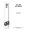
205 Williamson Square Franklin, TN 37064 Tel: 615/595-6665 Fax: 615/595-6610 FLEXTENSIONAL PIEZOELECTRIC ACTUATOR™ (FPA) USER MANUAL DYNAMIC STRUCTURES AND MATERIALS, LLC REV. 100323 205 Williamson Square Franklin, TN 37064 Tel: 615/595-6665 Fax: 615/595-6610 Table of Contents 1. 2. 3. 4. 5. 6. 7. 8. 9. 10. 11. 12. PERSONAL SAFETY WARNINGS AND CAUTIONS ...................................................... 2 OPERATING AND SERVICE PRECAUTIONS .................................................................. 3 Physical Features of DSM’s Piezoelectric Actuator Products ............................................... 3 Motion of a FPA Actuator ...................................................................................................... 5 Applied Piezo Voltage Input Limits ....................................................................................... 6 Actuator Static Operation ...................................................................................................... 6 Actuator Dynamic Operation ................................................................................................. 6 Actuator Position Output and Hysteresis ............................................................................... 7 Appropriate Mounting and Loading of a FPA Actuator ......................................................... 8 Piezo Self Heating and Operational Duty Cycle Limits .......................................................11 Preferred environmental operating conditions ..................................................................... 12 General Sources for Additional Information........................................................................ 13 Appendix - Application Notes a) An Introduction to Piezo-Actuation b) Flextensional Piezoelectric Actuation c) Mounting Piezo Actuators d) Isolating Piezo Actuators from Moments e) Design Challenges with Piezo-Actuation f) Piezo-Actuators driving Spring Loads V. 100601 1 205 Williamson Square Franklin, TN 37064 Tel: 615/595-6665 Fax: 615/595-6610 1. PERSONAL SAFETY WARNINGS AND CAUTIONS Please review the following points for both personal and equipment safety while operating any of DSM’s piezoelectric actuator products. Do not substitute parts or make any unauthorized modifications to the actuator. To ensure that its mechanical and electrical integrity are not compromised, please contact DSM for service and repair. High Energy/Voltage Warnings Exercise caution when using piezoelectric devices. High energy levels can be stored in the actuator’s piezoelectric elements, which are capacitive in nature. CAUTION AC Source Grounding Warning Ensure that the amplifier or driver used for controlling the actuator is connected to a grounded AC outlet with the recommended AC input connector configured for the available line voltage. There is a shock hazard if the amplifier chassis and cover are not connected to an electrical ground via the safety ground in the AC input connector. RISK OF DANGER In addition, the piezoelectric actuator must be mounted to a surface that is electrically grounded in order to avoid a potentially harmful voltage differential between the actuator and grounded objects. V. 100601 2 205 Williamson Square Franklin, TN 37064 Tel: 615/595-6665 Fax: 615/595-6610 2. OPERATING AND SERVICE PRECAUTIONS DSM’s flexure-guided piezoelectric actuators incorporate advanced materials and engineering for precision motion. The piezo actuators can easily be damaged from improper use and/or exposure to harmful environments. Improper uses include but are not limited to applications such as the following examples: • DO NOT: introduce static compressive loads exceeding 100% of an actuator’s blocked force rating • DO NOT: drive the actuator in a way that creates impacts between the actuator and other rigid surfaces. Strive to avoid dropping the actuator. • DO NOT: cycle the actuator beyond 80% of the first natural frequency corresponding to the loaded condition • DO NOT: introduce loading conditions that create bending moments in the actuator’s frame • DO NOT: introduce lateral or transverse loading of the actuator’s output pad or mounting point that exceeds 5% of the actuator’s blocked force rating • DO NOT: drive an actuator with a step input or square wave. (If rapid response is required, DSM recommends using a half-sinusoidal transition with frequency not exceeding 50% of the actuators first natural frequency corresponding to the loaded condition.) • Accidental, extreme voltage changes may damage the piezo material within the actuator. Extreme voltage changes may occur if a plug power plug is pulled or a piezo amplifier overvoltages or undervoltages the actuator. DSM recommends using only DSM piezo amplifiers with DSM piezo actuators. • DO NOT: introduce tensile loading into actuator frame. Prying or twisting of the actuator frame may damage the mechanism. • DO NOT: allow the piezo within the actuator to come in contact with water. All water and alcohol liquid must be removed prior to operation. Humidity levels must be reduced to the level recommended in section 11. Note that isopropyl alcohol may have high levels of water and should not come in contact with the actuator. Please contact DSM to determine the suitability of these flexure devices for your particular application’s requirements. 3. PHYSICAL FEATURES OF DSM’S PIEZOELECTRIC ACTUATOR PRODUCTS DSM has designed its flexure-guided piezoelectric actuator products to deliver reliable motion and force output. The figure below illustrates the physical features of a traditional DSM FlexFrame PiezoActuator™. The standard mounting orientation of this type of actuator is also shown below. V. 100601 3 205 Williamson Square Franklin, TN 37064 Tel: 615/595-6665 Fax: 615/595-6610 Output connection with a mounting hole (threaded hole size is variable) Metal flexure frame (metal type determined by application) Ground wire of the piezo stack Multi-layer piezoelectric “stack” Positive wire of the piezo stack Spring preload strap Base mounting connection with a threaded hole Representative FlexFrame PiezoActuator™ DSM’s typical FlexFrame PiezoActuator™ consists of a metal flexure frame, spring preload straps, and a piezoelectric “stack.” The piezo stack is equipped with two electrical lead wires, typically red (positive) and black (ground). Please refer to FlexFrame PiezoActuator™ electrical wiring options and connection diagrams for wiring details. Mounting screws should be length-sized to prevent them from passing through the threaded mounting connections of the actuator frame. If a mounting screw is too long it may impinge on the piezoelectric stack in the center of the actuator frame and damage the piezo, resulting in failure of the mechanism. Customized metal frames, piezo stack elements, and preload straps are necessary for specialized applications. The metal frame material of the FlexFrame PiezoActuator™ can be made from nonmagnetic material for high magnetic field applications. Titanium frames can be used for cryogenic and/or vacuum applications. Composite frame materials can be implemented where weight savings is crucial. DSM has piezoelectric actuator design experience with various extreme environments, such as high magnetic field (MRI), thermal (cryogenic or rocket), and vacuum (space) applications. Please contact DSM for application related questions or cost considerations. V. 100601 4 205 Williamson Square Franklin, TN 37064 Tel: 615/595-6665 Fax: 615/595-6610 4. MOTION OF A FPA ACTUATOR A voltage potential applied to the electrical leads of the piezo actuator results in a small physical expansion of the piezoelectric stack along its length. The lengthwise expansion of the piezo stack is amplified with a mechanical flexure frame, as shown in the figure below. As a result of the mechanical leverage created by the actuator’s flexure arms, the piezo stack’s lengthwise motion is translated into vertical motion of the actuator’s top and bottom mounting flanges. The figure below shows the exaggerated motion from a finite element model of an expanding FlexFrame PiezoActuator™. Direction of Motion Piezo stack length Mounting pad attached to a fixed base Exaggerated shape of actuated FlexFrame PiezoActuator™ (dark blue) superimposed over the original shape of the same actuator (light green) indicates the actuation direction. The vertical motion of the FlexFrame PiezoActuator™, as shown in the figure above, is expanding away from the piezo. Actuators can be designed to expand or contract when voltage is applied to the piezo stack. A detailed plot and explanation of the actuator stroke vs. applied piezo voltage will be shown later in this document. V. 100601 5 205 Williamson Square Franklin, TN 37064 Tel: 615/595-6665 Fax: 615/595-6610 5. APPLIED PIEZO VOLTAGE INPUT LIMITS The recommended voltage limit for DSM’s standard piezoelectric stack is a signal operating between –30 V and +150 DC. It is preferable to drive the actuator with a sine wave as input for high frequency actuation, because the extremely high-frequency components of square waves and triangle waves will decrease the expected life of the piezo stack, eventually leading to premature stack failure. When operating a piezoelectric actuator, take care not to subject the device to voltage spikes at or near maximum voltage, (which can occur when turning on an amplifier), as these spikes can also damage the piezo stack. Piezoelectric materials are very responsive, and high frequency drive signals can cause the material to experience damaging tensile stresses. 6. ACTUATOR STATIC OPERATION The actuator can be operated at static or near-static conditions using only a power supply and a voltmeter. The input voltage can be adjusted until the desired displacement level is achieved. Use the voltmeter to verify that the input signal is within the actuator’s rated voltage range (i.e., –30V to +150V). At higher humidity levels, prolonged DC Voltage can lead to stack degradation. 7. ACTUATOR DYNAMIC OPERATION Typical dynamic operation of a FlexFrame PiezoActuator™ device involves an analog output device (e.g., function/signal generator, data acquisition card) and a piezo linear amplifier. Prior to connecting the piezo stack in the FPA actuator to the piezo linear amplifier device, DSM recommends auditing the analog signal. Use the piezo linear amplifier to drive a capacitor that is equal to the capacitance of the piezo actuator and rated for high voltage levels. Monitor the voltage applied to the capacitor from the linear amplifier with an oscilloscope to ensure that the voltage limits and waveform are appropriate for the rating of the piezo stack. Use proper electrical caution while working with all high voltage devices and connections. The analog output device provides the signal to the linear piezo amplifier, which in turn is electrically connected to the piezoelectric actuator. During dynamic operation, it is important that the actuator is not driven at or near the actuator’s loaded resonant frequency. Operation at or near the actuator’s loaded resonant frequency may cause the displacement of the mechanism to exceed the actuator’s rated displacement. If a FPA actuator is driven in a dynamic manner where it exceeds its rated stroke by more than 20%, high cycle fatigue may occur in the flexure elements of the actuator frame. In high cycle fatigue, the flexures may snap and the piezoceramic may electrically fail as a result of unbalanced loading. Several solutions may be considered to avoid over-stroke of the piezo actuator in dynamic applications. The FPA actuator might be linked to the applied mass load with a spring to “decouple” the mass. Another option may be a bumper or stroke limiter placed in the V. 100601 6 205 Williamson Square Franklin, TN 37064 Tel: 615/595-6665 Fax: 615/595-6610 mechanism to prevent over-stroke. Alternatively consider driving the actuator at or near a loaded resonance condition only with a very low peak-to-peak input voltage with the actuator’s displacement monitored. Consider hiring DSM to analyze your load application to avoid damaging the actuator mechanism. The piezoelectric stack is very responsive to electrical ripple on the input signal. If the input signal has a low-amplitude, high-frequency ripple component, the actuator frame may not dynamically respond with corresponding motion, but the piezoelectric stack may respond and vibrate or chatter within the frame. For example, if a low resolution motion card or DAC (digital to analog conversion) card is used to produce the signal to the piezoelectric device, there might be some filtering ripple on top of the input signal. If the noise is not filtered out, it may manifest itself as a high frequency noise that can be heard emanating from the actuator. Although the actuator frame cannot respond dynamically to these signals, the piezo stack has the ability to respond and follow voltage signals up to 20 KHz. 8. ACTUATOR POSITION OUTPUT AND HYSTERESIS Actuator motion is proportional to the voltage applied to the piezo stack. The actuator motion is extremely repeatable due to the solid-state nature of the device and the sensitivity of piezo material to the applied voltage. When a piezoelectric actuator is cycled from one voltage level to another and then back, a hysteresis behavior can be seen in the actuator’s response. The hysteresis exhibited by the actuator displacement plot is a function of the piezo material not mechanical issues. Piezo hysteresis is extremely repeatable. The plot below depicts the displacement hysteresis of a FPA actuator vs. applied voltage. V. 100601 7 205 Williamson Square Franklin, TN 37064 Tel: 615/595-6665 Fax: 615/595-6610 FPA actuator displacement vs. voltage and the inherent piezo hysteresis The two curves shown in the graph are representative of the hysteresis at full voltage stroke, and this is quantified as 10-15% for typical piezoelectric materials. In practical application, the presence of hysteresis dictates that the actuator’s position at a given voltage level will be slightly different depending upon whether the voltage was attained by increasing or decreasing the applied voltage. The value of the difference is a percentage of the entire voltage change. For example, if the applied voltage change corresponds to a motion change of 50 microns, there is 5 to 7.5 microns of hysteresis, etc. Implementing a closed loop control algorithm can reduce or eliminate hysteresis. Contact DSM for the latest research and options for overcoming the effects of hysteresis. 9. APPROPRIATE MOUNTING AND LOADING OF A FPA ACTUATOR FPA devices are designed to accept loading directly through the axis of motion. The loading should be applied orthogonal to the mounting surface of the actuator output block (Y-axis as shown in the figure below). V. 100601 8 205 Williamson Square Franklin, TN 37064 Tel: 615/595-6665 Fax: 615/595-6610 Appropriate loading condition for a FPA actuator All loading must be applied uniformly and axially through the mechanism. Lateral or transverse shear loads and bending loads may cause damage to the actuator frame. This limitation applies to both static and dynamic loading and any combination of the two. Care should be applied to verify that any dynamic loading (operating at high frequency with an attached mass) does not exceed the recommended load. Sample FPA Piezoelectric Actuator with Mounting or Applied Moments to Avoid V. 100601 9 205 Williamson Square Franklin, TN 37064 Tel: 615/595-6665 Fax: 615/595-6610 Mounting Recommendations 1. When attaching the actuator to a mounting surface, use a clamp or wrench to support the actuator output block to prevent the Y-axis twisting moment from damaging the actuator. 2. Use a spherical coupling or flexure coupling to prevent X-axis and Z-axis moments from damaging the actuator during electrical operation or actuator motion. 3. Apply a linear guidance bearing to the moving output to carry any moment loads that may be present and to prevent them from damaging the actuator. Actuator Force Output and Available Stroke The magnitude of the applied load should not exceed the “blocked force” rating of the actuator. The blocked force rating is a product of the stroke and the stiffness of the actuator. Example: DSM’s FPA-0100E-S-0518-150-SS has a rated stiffness of 1.8 N/micron and a rated displacement of 100 microns over the standard –30 to +150V range. Therefore, the maximum recommended load (block force) is 180 N for this model. DSM defines a piezo actuator's "blocked force" as being that force which is required to compress/extend a fully extended/contracted actuator back to its zero position. In most cases, DSM designs the actuator's flexures such that the blocked force corresponds to the flexures' maximum design stress. Even under a static load equal to an actuator's blocked force, the actuator will be able to move through its full range of motion and will respond rapidly to changes in the applied voltage field. The static load simply shifts the actuator's static position. An analogous situation is to think of the piezo actuator as a spring that has a static load placed upon it. The static load compresses the spring (piezo) to a new static position. Subsequent changes in temperature (voltage) cause the spring (piezo) to change dimensions. Piezo actuators have an inverse, linear relationship between their force capacity (for pushing against a spring-type load) and their displacement. At zero displacement, an actuator has maximum force capacity, and at maximum displacement the force capacity has dropped to zero. When a piezo actuator pushes against a spring load, the actuator will stroke outward while pushing against the spring until a force balance is achieved between the actuator and the spring load (limited by the actuator’s displacement range). Please refer to DSM’s application note on this topic for additional information: http://www.dynamic-structures.com/pdf/driving_spring_loads.pdf Transverse and Lateral Loading of the the FPA Mounting Surface If X-axis and Z-axis transverse loads are applied to the FPA output plate, they can cause damage to the guiding actuator flexures and piezoceramic transducer. Care must be applied to prevent V. 100601 10 205 Williamson Square Franklin, TN 37064 Tel: 615/595-6665 Fax: 615/595-6610 these loads from being applied to the actuator. Such loads will cause severe moments to occur in the actuator body - leading to flexure and piezoceramic failure. Use of an external guiding support (flexure, blade spring, etc) to carry transverse loads is appropriate to prevent them from being applied to the actuator moving output surface. Contact DSM if you have questions about your application. Sample FPA Piezoelectric Actuator with Transverse Mounting Loads (Orange and Green) to Avoid 10.PIEZO SELF HEATING AND OPERATIONAL DUTY CYCLE LIMITS Piezoelectric materials are capacitive in nature, but these materials also have some internal, resistive losses that can lead to destructive self-heating under high dynamic operation. High levels of electrical current can flow in and out of the actuator depending upon the driving waveform and the associated rate of change of the applied voltage field. Peak current for a “straight line” voltage change is calculated as Current (Amps) = Capacitance x dV/dt (where dV/dt is the instantaneous change in voltage with respect to time). The rate of change in voltage with respect to time is directly related to operational frequency. Operation with a square wave driving waveform usually requires a very high change in voltage in a very short time span. Please check the expected operational current and heat up before using the piezoelectric actuators in applications where the duty-cycle or operational frequency may cause the external stack temperature of the piezo stacks to exceed 80 C. A smaller cross section piezo stack (e.g., 5x5 mm cross section) can likely be driven over a 0-150 V range at up to 300-350 Hz continuously without exceeding a steady-state stack temperature of 80 C. A large stack (e.g., 10x10 mm cross section) would be likely limited to approximately 150 V. 100601 11 205 Williamson Square Franklin, TN 37064 Tel: 615/595-6665 Fax: 615/595-6610 Hz for 0-150 V continuous operation in order to maintain the steady-state surface temperature below 80 C. The heat-up of the actuator depends on the application duty cycle among other factors. For applications where the user detects that the actuator temperature is approaching 80 C, DSM recommends the addition of forced air convection to aid in cooling the stack. As a result of the many factors that can affect the thermal condition of the piezoelectric stacks, please consult with DSM regarding your requirements. DSM cannot guarantee satisfactory performance under all conditions. 11.PREFERRED ENVIRONMENTAL OPERATING CONDITIONS A standard piezoelectric actuator will be designed to operate in the following environment. Any deviation from the specified environment must be approved by DSM and may result on the voiding of any warranty. Any deviation not approved by DSM will be grounds for voiding of any warranty. • • • Environmental temperature for full stroke operation at less than 200 Hz: Percent relative humidity: Operating supply voltage: 15 to 50 degrees Celsius* 0-50% -30 to +150 V** * NOTE: The output stroke of piezoelectric material decreases linearly from room temperature (25C) down to -273C, where displacement output is assumed to be zero. With this in mind, the motion range of a standard piezoelectric actuator will be about 20% less at -40C than at room temperature. ** This is the typical operating voltage for the majority of DSM’s actuator products, but some products are rated for up to 200V. Please see your respective quotation and/or product design data. CAUTION: As with any electrical device, do not spill liquids on or immerse piezoelectric actuators and drive electronics. This may cause electrical shock or short circuit of the devices. Please contact DSM for applications requiring temperature or relative humidity conditions outside of that recommended above. Vacuum and Specialty Environments V. 100601 12 205 Williamson Square Franklin, TN 37064 Tel: 615/595-6665 Fax: 615/595-6610 DSM’s customers have used our piezoelectric actuator designs in vacuum and specialty environments (MRI, etc) with great success. The performance of the actuator in any unique environment is the responsibility of the user. Based on some limited experience, DSM estimates that operation of the piezoelectric actuator devices in the following environments will not cause any difficulties. Helium, Argon, Nitrogen. 12.GENERAL SOURCES FOR ADDITIONAL INFORMATION DSM recieves piezo projects from time to time, that require additional piezo testing in novel environments, new electrical configurations, or inovative mounting techniques. The testing that DSM completes often yields new information that is publishable. The reader is encouraged to review DSM’s website for piezo information and new products. http://www.dynamic-structures.com/index.html DSM is familiar with several manufacturers of piezoelectric materials used in motion control devices. The reader is encouraged to review theses manufactures’ websites for additional information on piezoelectric actuators http://www.physikinstrumente.com/en/index.php http://www.piezomechanik.com/en/home/allcatalogs/index.html http://www.noliac.com/Noliac_publications_-675.aspx http://www.morganelectroceramics.com/access-pzbook.html V. 100601 13 205 Williamson Square Franklin, TN 37064 Tel: 615/595-6665 Fax: 615/595-6610 often used in DSM’s piezo-actuators. PZT stacks expand in the column direction as represented in Figure 1. Piezoelectric Actuation Mechanisms: An Introduction Using piezo-actuators requires an understanding of actuator mechanical and electrical performance issues. Understanding the basic operating concepts behind piezo-actuators may also be beneficial to controlling and operating the piezo-actuators. The following information on piezo-actuator design and performance issues can be helpful when comparing piezoelectric-based actuators to more conventional electromagnetic actuators (solenoids, motors, voicecoils) and other “induced strain actuator” materials such as electrostrictive ceramic, magnetostrictive, and shape memory alloys. Applications for Piezo-Actuators Actuators based on piezoelectric ceramic material prime movers (or piezo-actuators) are finding broad acceptance in applications where precision motion and/or high frequency operation is required. Piezoactuators can produce smooth continuous motion with resolution levels at the nanometer and subnanometer level. This property makes them useful in precision positioning and scanning systems. The very fast response times, wide operating bandwidth, and high specific force may be beneficial for applications in fluid valve control, optical scanning, vibration isolation, and precision machining. Using the Piezoelectric Effect to Generate Motion and Force Producing Displacement: DSM uses the term “piezoactuator” for actuator or motion generating devices that use electro-expansive ceramic materials such as lead zirconate titanate (PZT), as the prime mover. Piezoelectric materials exhibit an effect whereby they expand or contract in the presence of an applied electric field. This “induced strain” or change in length occurs as electrical dipoles in the material rotate to align with an orientation that more closely aligns with the direction of the applied electric field. The change in length is generally proportional to the field strength as applied via the device actuation voltage. A typical value for length change might be 0.1 percent of the total material length in the direction of the applied field. For example, when actuated, a 1 mm thick layer of PZT will increase in thickness by one micron. A monolithic stack of PZT layers and electrodes (called a PZT stack) is most [email protected] Appendix (a) Figure 1 – Example of PZT stack expansion PZT material fabricators supply their materials in the stack geometry to best leverage the piezoelectric effect at low voltages. A stack consists of many thin layers of PZT ceramic laminated together and electrically connected in parallel. PZT stacks come in various sizes and shapes and can be combined to produce extended motion. Useful expansions can be achieved at voltage levels as low as 10 volts, although many fabricators design their low voltage stacks for operation up to 150 volts. PZT stacks are typically available in circular or rectangular crosssections from 1 mm to 14 mm across and in lengths as small as a few millimeters. Other form factors for PZT in actuator applications include tubes and thin patches or strips bonded to one or both sides of a substrate material. DSM has developed a number of actuators that use mechanical amplification to enhance the small levels of expansion found in PZT materials (see “Amplification Mechanisms” Techbrief). These actuator mechanisms leverage the high force and small stroke of PZT materials to create many times greater stroke levels. Figures 2, 3, 4, and 5 represent some of the basic piezo-actuator amplification concepts for PZT stacks and thin patches. Displacement amplification lever-arm PZT stack transducer Figure 2 – Simple lever-arm mechanism www.dynamic-structures.com 205 Williamson Square Franklin, TN 37064 Tel: 615/595-6665 Fax: 615/595-6610 the stiffness of the external load is high enough to prevent expansion of the PZT. Typical blocked pressure levels are 5 to 7 ksi (34 to 48 MPa). Strengths of Piezo-Actuators Figure 3 – DSM LPA-100 piezo-actuator uses a simple lever-arm mechanical amplification. (PZT stack is green output is in vertical direction) PZ T Subst rate Ze ro Potenti al A ppl ied Posi ti ve Potential A ppl ied Figure 4 – PZT uni-morph patch amplification Figure 5 - A miniature piezo actuator for a 70 um displacement switching application uses a uni-morph amplification concept. Producing Force: PZT stacks are displacementgenerating devices. They expand proportionally to the applied electric field or actuation voltage. Maximum motion or expansion of the PZT occurs at maximum actuation voltage. When an external load resists the motion of the PZT expansion, the PZT stacks apply a force that is a function of the stiffness of the external load. The PZT stacks can generate a very high level of pressure against an external load if [email protected] Appendix (a) Given the relatively small displacement that a PZT stack can develop, piezo actuators have unique design considerations. For example, piezoactuators excel in precision positioning applications where small, high-force moves are desirable. When fabricating, measuring, or testing extremely small structures or features, piezo-actuators can provide very smooth and continuous motion over a range of a few microns to a few millimeters. With proper system design, piezo-actuators hold the potential for high speed operation. Generally, the response time of a piezo-stack is limited by the speed of sound in the material. Therefore, natural frequency of a PZT stack may be several kiloHertz. Even with the added mass and lower stiffness of an amplification mechanism, the natural frequency of an amplified piezo-actuator may be a few kiloHertz. Additionally, when designed and constructed properly, piezo-actuators can exhibit the following strengths. • solid-state construction with zero backlash, stiction, or cogging • low or zero power position hold capability • very high frequency response (bandwidth) • very high force per unit area (force and stroke directly scales with size) • little or no outgassing or particle generation as flexure based designs have little or no friction and require no lubrication • relatively low heat generation • highly scaleable and reliable Summary DSM’s piezo-actuators harness the small precise amount of expansion generated by the piezoelectric effect to produce a wide range of actuator solutions. With proper design, piezo-actuators have performance attributes and properties that can be valuable in precision positioning, vibration control, and scanning applications. Smooth, precise motion from the sub-nanometer to multiple-millimeter level is possible with a variety of solid-state actuation/amplification mechanisms. www.dynamic-structures.com 205 Williamson Square Franklin, TN 37064 Tel: 615/595-6665 Fax: 615/595-6610 Piezoelectric Actuation Mechanisms: Flextensional Piezo-Actuator Operation Solid State Kinematic Elements The active element in DSM’s flextensional piezoelectric actuator (FPA) architecture is the “PZT stack” in the center of the frame. As the applied voltage on the piezo stack is increased, the PZT stack expands (see DSM App Note - An Introduction to Piezo-Actuation). DSM’s FPA mechanism design mechanically amplifies this expansion (in the long dimension of the piezo stack) through the solid-state kinematic elements in the metal frame wrapped around the PZT stack. The kinematic elements in the amplification frame include links or blocks (thicker metal sections) connected by thin metal webs called “flexures.” The flexures act like frictionless hinges. They are designed to flex within their material fatigue stress limit for the given stroke capability of the actuator. For example, in the picture of the FPA-80E actuator below, a simple yellow line is traced through the flexures of the top arms of the actuator. As the PZT stack expands and pushes on the actuator’s end blocks along the line of action indicated by the white arrow, this line straightens a small amount to produce the 80 microns of amplified motion in the direction indicated by the black arrow. the PZT stack increases, the actuator assembly expands outward. Over the full rated voltage range of the FPA-80E, the actuator typically achieves a nominal displacement range of 80-90 microns. This level of motion results from the amplification of the piezo stack’s output motion of approximately 20 microns. The PZT material can also be driven to a small negative voltage. Under a negative voltage, the piezo material actually contracts (its length becomes shorter than at the zero voltage condition). The normally expanding piezo-actuator retracts when a negative voltage is applied. The results of a finite element model of an FPA100E show the exaggerated motion of the piezoelectric actuation. Figure 2 shows the results of a displacement analysis of the FPA-100E scaled by a factor of 20. Direction of Motion Figure 2 - Exaggerated shape of actuated FPA-100E (dark blue) superimposed over original, non-actuated shape of FPA-100E (light green) indicates the actuation direction. Direction of amplified motion The spring wire that runs across the actuator frame on both sides applies a preload that keeps the piezo ceramic in compression. The preload allows the actuator to function in contraction and expansion even when the dominant motion of the PZT stack causes expansion. The spring preload works to restore the actuator frame to its original position. When voltage on the piezo is reduced, the piezo contracts. The spring preload pulls the end blocks of the amplification frame towards one another, causing the actuator output to contract. Direction of piezo material expansion Figure 1 - PZT stack expansion in FPA-80E Contraction vs. Expansion in Piezo-Actuators The FPA-80E is designed as an “expansion” or “push” actuator. As the actuation voltage applied to [email protected] If an application requires a piezo-actuator with the dominant motion in a pulling/contracting mode, reversing the kinematic design of actuator causes the output points of the frame to contract as the piezo expands. The picture of DSM’s FPA-1100C in Figure 3 shows the imaginary yellow line connecting Appendix (b) www.dynamic-structures.com 205 Williamson Square Franklin, TN 37064 Tel: 615/595-6665 Fax: 615/595-6610 through the flexures that flattens out as the piezo material expands. Direction of amplified motion Direction of piezo material expansion Figure 3 – FPA-1100-C showing the direction of piezo material expansion and direction of amplified motion The comparison of the kinematic configurations of the FPA-80E and the FPA-1100C shows how the expansion of the piezo material can be used to create either an expansion/pushing (i.e., FPA-80E) action or a contracting/pulling (i.e., FPA-1100C) action. In both cases, the spring preload enables bidirectional motion as the piezo expands and contracts under a changing applied actuation voltage. Summary DSM’s piezo-actuators harness the small precise amount of expansion generated by the piezoelectric effect to produce a wide range of actuator solutions. The Flextensional Piezoelectric Actuator FPA design represents a compact, high-stiffness means of producing highly-amplified piezoelectric-controlled motion. DSM also produces a line of Leveraged Piezoelectric Actuators which are based on solidstate kinematic lever mechanisms and generally provide a higher dynamic bandwidth than the FPA series. With proper design, piezo-actuators have performance attributes and properties that can be valuable in precision positioning, vibration control, and scanning applications. Smooth, precise motion from the sub-nanometer to multiple-millimeter level is possible with a variety of solid-state actuation mechanisms. [email protected] Appendix (b) www.dynamic-structures.com 205 Williamson Square Franklin, TN 37064 Tel: 615/595-6665 Fax: 615/595-6610 Piezo Actuators - Mounting and Handling Guidelines Improper use includes the following but is not limited to applications such as the following : • • • • • • • • • DO NOT: introduce static compressive loads exceeding an actuator’s blocked force rating DO NOT: drive the actuator in a way that creates impacts between the actuator and other rigid surfaces. Avoid dropping the actuator. DO NOT: cycle the actuator beyond 80% of the first natural frequency of the mass loaded condition DO NOT: introduce loading conditions that create bending moments in the actuator’s frame DO NOT: introduce lateral or transverse loading of the actuator’s output pad or mounting point that exceeds 5% of the actuator’s force rating DO NOT: drive an actuator with a step input or square wave. (If rapid response is required, DSM recommends using a half-sinusoidal transition with frequency not exceeding 50% of the actuators first natural frequency of the loaded condition.) Accidental, extreme voltage changes may damage the piezo material within the actuator. Extreme voltage changes may occur if a plug power plug is pulled or a piezo amplifier overvoltages or undervoltages the actuator. DSM recommends using only DSM piezo amplifiers with DSM piezo actuators. DO NOT: introduce tensile loading into actuator frame. Prying or twisting of the actuator frame may damage the mechanism. DO NOT: allow the piezo within the actuator to come in contact with water. All water and alcohol liquid must be removed prior to operation. Humidity levels must be reduced to the level recommended in section 11. Note that isopropyl alcohol may have high levels of water and should not come in contact with the actuator. Proper Uses Amplified piezoelectric actuators may be loaded only through their output plates in the direction co-axial with the output displacement. All loading must be applied uniformly and axially through the mechanism. The applied forces must be centered very well on the mounting face. Tilting and shearing loads must be avoided or else they will damage the actuator. Lateral or transverse loads and bending loads may cause damage to the actuator [email protected] Appendix (c), p. 1 ceramics and frame. Lack of parallelism between mounting faces can be a principal cause of actuator failure. This type of failure can be prevented by using ball tips, flexible tips, adequate guiding mechanisms etc. Appropriate loading direction for an FPA This limitation applies to both static and dynamic loading and any combination of the two. Care should be applied to verify that any dynamic loading (operating at high frequency with an attached mass) does not exceed the recommended load. The flat output surfaces of the actuator should be mounted to a precision flat and smooth-ground, nonrotating surface. The FPA actuator should not be expected to carry moments and transverse forces. Supplemental guidance like bearings or flexures should be used if loads greater than 5% of the product of the actuator stiffness and stroke must be supported. Avoid Applied or Reaction Moments to the Output of the FPA Piezoelectric Actuator X-axis, Y-axis, and Z-axis moments if applied to the output plate of the FPA can cause damage to the guiding www.dynamic-structures.com 205 Williamson Square Franklin, TN 37064 Tel: 615/595-6665 Fax: 615/595-6610 actuator flexures. Mis-alignments between the mounting surface and the moving surface can lead to failures during mounting and electrical operation of the actuator. If a moment remains on the mounting surface when the actuator is energized, the moment applies an additive stress to the actuator flexures and the piezoceramic. The additional mounting stress can cause the stress in the actuator flexures to exceed the design stress. Use of a plain-faced mounting to the plain face of the actuator should only be attempted if a proper application analysis verifies that the X-axis and Z-axis moment loads are minimal. Otherwise, use a spherical coupling or flexure hinges to decouple the moment loads from the actuator. Consider having DSM analyze your mounting and loading conditions if you have questions about your application. Mounting Recommendations 1. 2. 3. 4. 5. 6. 7. When attaching the actuator to a mounting surface, use a clamp or wrench to support the actuator output block while leaving the opposite end of the actuator free to prevent the Y-axis twisting moment from damaging the actuator. Use a spherical coupling or flexure coupling to prevent X-axis and Z-axis moments from damaging the actuator during electrical operation or actuator motion. Apply a linear guidance bearing to the moving output to carry any moment loads that may be present and to prevent them from damaging the actuator. If using adhesive to mount actuators, use ground surfaces. During curing, do not exceed the operational temperature range of the actuator. The environment of all actuators should be as dry as possible. The combination of high electric DC fields and high relative humidity values should be avoided with all piezoelectric actuators. Because the piezoelectric ceramics in the actuator can develop a charge when handled and under temperature loading, it is important to keep the actuator leads short circuited during mounting and handling. Piezo actuators are sensitive to moisture, high relative humidity, liquids and contact with any other electrically conductive materials. Avoid operating actuators under these environmental conditions since they can cause dielectric breakdown. [email protected] Appendix (c), p. 2 Actuator Force Output and Available Stroke The magnitude of the applied load should not exceed the “blocked force” rating of the actuator. The blocked force rating is a product of the stroke and the stiffness of the actuator. Example: DSM’s FPA-0100E-S-0518-150-SS has a rated stiffness of 1.8 N/micron and a rated displacement of 100 microns over the standard –30 to +150V range. Therefore, the maximum recommended load (block force) is 180 N for this model. DSM defines a piezo actuator's "blocked force" as being that force which is required to compress/extend a fully extended/contracted actuator back to its zero position. In most cases, DSM designs the actuator's flexures such that the blocked force corresponds to the flexures' maximum design stress. Even under a static load equal to an actuator's blocked force, the actuator will be able to move through its full range of motion and will respond rapidly to changes in the applied voltage field. The static load simply shifts the actuator's static position. An analogous situation is to think of the piezo actuator as a spring that has a static load placed upon it. The static load compresses the spring (piezo) to a new static position. Subsequent changes in temperature (voltage) cause the spring (piezo) to change dimensions. Sample FPA Piezoelectric Actuator with Transverse Mounting Loads (Orange and Green) to Avoid www.dynamic-structures.com 205 Williamson Square Franklin, TN 37064 Tel: 615/595-6665 Fax: 615/595-6610 Isolating FPA and LFPA Piezo Actuators from Moment and Lateral Loading As described in the application note, “Piezo Actuators - Mounting and Handling Guidelines”, mounting hardware must not apply a moment or lateral loading to the output faces of the actuator frames. If mounting conditions or loading may apply a moment or allow lateral motion, the user should apply isolation flexures or ball pivots to the actuator’s output faces or use supplementary bearing stages to carry the moments or lateral loads. Simple Spherical Pivots A example of a simple isolation method using hemisphere pivots is shown in Figure 1. The wrapped around frame may be comprised of conventional hinge mechanisms or a flexure using a resilient material. Spherical pivots can be full or hemispheres and may be captured in machined divots in the wrap around frame. Figure 2 – Using Spherical Endcaps in a Spring-loaded Follower Plate to Limit Moment and Lateral Loading Simple Flexure Joints A example of a simple flexure method for isolating the actuator using cross flexures is shown in Figure 3. Another option is the use of conventional shaker stingers (like those on voice-coil shakers) on the actuator outputs. Figure 3 – Using Flexure Joints on the Output of the Actuator to Limit Moment and Lateral Loading Figure 1 – Using Spherical Endcaps in a Flexure frame to isolate Piezo-Actuator from Lateral or Moment Loading The follower frame can also be designed with a spring preload in order to carry any stretching load that might act to separate the frame from the Piezo-Actuator. Figure 2 shows a different scheme for achieving the same purposes. [email protected] Appendix (d) Naturally, when flexures, stingers or spherical joints are used, off axis loading will cause rotation of the unit. External guidance (Figure 1) or external stages like ball or crossed roller stages will prevent such rotation. DSM can be contracted to design a suitable frame for your application. www.dynamic-structures.com 205 Williamson Square Franklin, TN 37064 Tel: 615/595-6665 Fax: 615/595-6610 Developing piezo-actuators that feature precision motion capabilities presents an opportunity for creative solid-state mechanism design. DSM has developed strategies to deal with the challenge of short strokes and very high forces inherent to piezoelectric materials. Piezo-actuator design must account for the following issues. • • • • Reactive energy Hysteresis, creep, and temperature instability Spring effects - available force is not constant, but dependent on position Energy losses from compliance in the system Reactive Energy: Driving a piezo-actuator requires sourcing sufficient current from the driver (programmable power supply or amplifier) to produce the desired electrical field or voltage level in the PZT stack. Because PZT stacks have relatively high capacitance, only a small amount of the energy delivered by the driver is used to move the load. The majority of the current applied is in the form of reactive power. Thus, the driving electronics must be able to move a relatively large amount of charge in and out of the PZT stack. This is slightly analogous to a four-quadrant drive for a DC motor with the added complication that the load is capacitive rather than resistive. In short, the drive electronics for a piezo-actuator are specialized for driving capacitive loads. Hysteresis, Creep, Temperature Instability: Dipole hysteresis in piezoelectric actuator displacement manifests itself as a difference in displacement path in the forward stroke compared to the return stroke. Therefore, the correlation between voltage and strain in piezoelectric materials is typically not highly linear. Open-loop hysteresis is generally around 10 to 15% of full scale, depending upon the particular piezo material. The output of the piezo-actuator in a standard displacement graph reflects this variation in forward versus return path displacement (Figure 1). To compensate for the change in position, one must drive the piezo-actuator to a slightly different voltage in the return move to get back to the same starting position. The value of the stroke hysteresis is a percentage of the entire commanded stroke. For example, a 50 micron move would produce a hysteresis level of 5 to 7.5 microns. [email protected] Appendix (e) Since PZT stack expansion occurs when electrical dipoles in the material rotate, the expansion is susceptible to temperature, time, and material resistance effects. Changes in temperature cause dipole creep or variations in dipole mobility. Dwelling at a specific dipole orientation for a period of time manifests itself as slight mechanical creep or drift in the PZT displacement. Drift or creep of 1 to 3% might be manifested, therefore, DSM recommends the use of displacement feedback to achieve the very fine resolution possible in piezo-actuators. 700 600 Contraction Displacement (microns) Piezoelectric Actuation Mechanisms: Design Challenges With Piezo-Actuators 500 400 Expansion 300 200 100 Material Response Lag or Material Hysteresis (not the same as mechanical hysterisis) 0 -100 -50 0 50 100 150 200 250 300 Voltage Figure 1 - Voltage-Displacement curve for one of DSM's amplified piezo actuators in open loop motion. Note the hysteresis between the expansion and contraction paths. Spring Effects: A piezo-actuator acts like a spring; the force it develops is not constant over its range of motion as might be the case for a linear motor or air cylinder device. The force available from a piezoactuator progressively decreases as it extends. It is important to consider the stiffness of the actuator and the forces pushing against it to assure that it will operate correctly. Because the PZT stack is a displacement generating device and only develops force as its expansion is resisted, the amount of displacement and remaining pushing force are dependent on the stiffness of the applied load. DSM specializes in high stiffness actuators that can deliver long stroke/high force performance in compact sizes. Energy Losses from Compliance: Since piezoactuators produce small levels of displacement, any mechanical slop, play or backlash in the actuator system or in the mechanical connecting elements reduces the available work. As a result, DSM recommends working with a competent actuator designer to develop the appropriate connections and mountings systems incorporating piezo-actuators. www.dynamic-structures.com 205 Williamson Square Franklin, TN 37064 Tel: 615/595-6665 Fax: 615/595-6610 Application Note: Driving a Spring Load with a Piezoelectric Actuator When a piezo-actuator (whether amplified or non-amplified) is actuated against a spring load, it converts electrical energy into both motion and force. This force will vary according to the amount of expansion/contraction achieved by the piezo-actuator under the applied electrical field. When activated with an applied electric field, the piezo-actuator moves against the spring load until it reaches a force balance condition. If at this point the spring load were to be removed, the stored potential energy within the piezo-actuator would be converted completely into additional motion. Therefore, when working against a spring load, the amount of displacement that the piezo-actuator can produce in the spring load is less than the piezoactuator’s free zero-load displacement. The amount of displacement that the spring can be compressed or stretched is a function of the spring stiffness and the piezo-actuator stiffness. The following nomenclature will be used in this discussion: Constants k spr : stiffness or spring constant of the applied spring load k pzt : stiffness or spring constant of the piezo-actuator δ pzt , max : maximum displacement produced by the piezo-actuator with no load Fmax : maximum force capacity produced by the piezo-actuator when k spr is infinite Variables δ pzt : displacement produced by the piezo-actuator under the applied electric field Fpzt : force capacity produced by the piezo-actuator as it moves against a spring load Piezo-actuators have an inverse, linear relationship between their force capacity (for pushing against a spring-type load) and their displacement. At zero displacement, an actuator has maximum force capacity ( Fmax ). At maximum displacement ( δ pzt , max ) under the maximum applied rated voltage, the force capacity is zero. Similarly, when the stiffness of the spring load ( k spr ) is zero, the piezo-actuator is able to achieve δ pzt , max . When k spr is infinite, the piezoactuator is not able to move against the applied spring load and instead produces its maximum force capacity Fmax against that load under the maximum rated voltage condition. The maximum force capacity Fmax can be approximated by the product of δ pzt , max and the piezo-actuator’s stiffness k pzt . [email protected] www.dynamic-structures.com Appendix (f) 205 Williamson Square Franklin, TN 37064 Tel: 615/595-6665 Fax: 615/595-6610 One calculates the amount of stroke that the piezo-actuator can apply to the spring load using the following equations: Equations The linear force-displacement relationship for a piezo-actuator pushing against a spring load is defined as δ δ (1) δ pzt = δ pzt ,max − pzt ,max Fpzt or Fpzt = Fmax 1 − pzt δ Fmax pzt ,max where δ pzt is the deflection of the piezo-actuator and Fpzt is the corresponding force capacity that can be generated by the piezo-actuator at that deflection The force-displacement relationship of the spring load is defined as: (2) Fspr = δ spr k spr . Recognizing that at equilibrium the force provided by the piezo-actuator is equal in magnitude to the opposing force from the spring load, we can equate the expressions from (1) and (2): δ (3) Fspr = Fpzt = δ spr k spr = Fmax 1 − pzt δ pzt ,max At force equilibrium, the actuator has compressed the spring by a distance (4) δ pzt = δ spr Substituting (4) into (3) yields (5) δ spr F = Fmax k spr + max δ pzt ,max −1 = Fmax k spr + k pzt Generally, if the spring stiffness exceeds the piezo-actuator stiffness, less than one-half of the piezo-actuator's free displacement can be applied to the external spring. If the spring stiffness equals the piezo-actuator stiffness, than exactly one-half of the piezo-actuator's free displacement can be applied to the spring. If the spring stiffness is less than the piezo-actuator stiffness, more than one-half of the piezo-actuator's free displacement can be applied to the external spring. The [email protected] www.dynamic-structures.com Appendix (f) 205 Williamson Square Franklin, TN 37064 Tel: 615/595-6665 Fax: 615/595-6610 portion of the piezo-actuator's free displacement not applied to the external spring is stored in the piezo-actuator as potential energy. Examples of a piezo-actuator driving against a spring load FPA-100 piezo-actuator: nominal spring stiffness k pzt = 1.0 N/micron; nominal blocked force Fmax = 145 N. For reference, nominal displacement δ pzt , max = 145 microns. Case A: spring load having a stiffness of 0.25 N/micron (25% of the FPA-100 stiffness) Using Equation (5), we determine δ spr : δ spr = 145 N / [(0.25 N/µm) + 1 N/µm] = 116 µm Case B: spring load having a stiffness of 1.5 N/micron (150% of the FPA-100 stiffness) Using Equation (5), we determine δ spr : δ spr = 145 N / [(1.5 N/µm) + 1 N/µm] = 58 µm Case C: spring load having a stiffness of 1.0 N/micron (equivalent to the FPA-100 stiffness) Using Equation (5), we determine δ spr : δ spr = 145 N / [(1 N/µm) + 1 N/µm] = 72.5 µm [email protected] www.dynamic-structures.com Appendix (f)