1
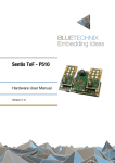
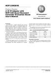
ToF-Flash
Hardware User Manual
Version 3.1
Contact
Bluetechnix
Waidhausenstraße 3/19
A-1140 Vienna
AUSTRIA
[email protected]
http://www.bluetechnix.com
Document No.: 100-1221-3
Date: 2014-10-02
© Bluetechnix 2014
Table of Contents
1
2
Introduction ....................................................................................................................................... 6
1.1
Overview .................................................................................................................................... 6
1.2
Key Features .............................................................................................................................. 6
System Architecture.......................................................................................................................... 7
2.1
Components .............................................................................................................................. 7
2.1.1
Power Supply ..................................................................................................................... 7
2.1.2
LVDS Clock Distributor....................................................................................................... 7
2.1.3
LIM ...................................................................................................................................... 7
2.2
Interfaces ................................................................................................................................... 7
2.2.1
Power Connector................................................................................................................ 7
2.2.2
Mod Light Connector ......................................................................................................... 8
2.3
LIM Addressing .......................................................................................................................... 8
2.4
Application Range...................................................................................................................... 9
2.4.1
IR-LED ................................................................................................................................ 9
2.4.2
Temperature Range ............................................................................................................ 9
2.5
Electrical Specifications ........................................................................................................... 10
2.5.1
Operating Conditions ....................................................................................................... 10
2.5.2
Absolute Maximum Ratings ............................................................................................. 10
2.5.3
Input current ..................................................................................................................... 11
2.5.4
Electrical Power Considerations ...................................................................................... 11
2.6
Mechanical Requirements ....................................................................................................... 12
2.6.1
Outline .............................................................................................................................. 12
2.6.2
LED Placement ................................................................................................................. 12
2.6.3
Cooling ............................................................................................................................. 13
2.6.4
Gap Pad ............................................................................................................................ 14
2.6.5
Mounting ........................................................................................................................... 14
2.6.6
ToF-Flash Adapter ............................................................................................................ 14
2.6.7
Cooling Plate .................................................................................................................... 14
2.7
Environmental requirements .................................................................................................... 15
2.7.1
Temperature ..................................................................................................................... 15
2.7.2
Humidity............................................................................................................................ 15
2.7.3
G-force, vibration.............................................................................................................. 15
2.8
EMC and safety requirements ................................................................................................. 15
3
Document Revision History ............................................................................................................ 16
A
List of Figures and Tables ............................................................................................................... 17
© Bluetechnix 2014
© Bluetechnix 2014
© Bluetechnix 2014
All Rights Reserved.
The information herein is given to describe certain components and shall not be considered as a guarantee
of characteristics.
Terms of delivery and rights of technical change reserved.
We hereby disclaim any warranties, including but not limited to warranties of non-infringement, regarding
circuits, descriptions and charts stated herein.
Bluetechnix makes and you receive no warranties or conditions, express, implied, statutory or in any
communication with you. Bluetechnix specifically disclaims any implied warranty of merchantability or fitness
for a particular purpose.
Bluetechnix takes no liability for any damages and errors causing of the usage of this board. The user of this
board is responsible by himself for the functionality of his application. He is allowed to use the board only if
he has the qualification. More information is found in the General Terms and Conditions (AGB).
Information
For further information on technology, delivery terms and conditions and prices please contact Bluetechnix
(http://www.bluetechnix.com).
Warning
Due to technical requirements components may contain dangerous substances.
© Bluetechnix 2014
Hardware Use Manual - ToF-Flash
1
Last change: 2 October 2014
Version 3.1
Introduction
1.1
Overview
The ToF-Flash is an external high-power IR-flash module for ToF depth sensors like the Argos-3D-P100, or
the Sentis-ToF-M100. The ToF-Flash is powered over a standard 2 pole terminal connector and receives a
synchronization signal via a 4 pole Interface connector.
1.2
Key Features
-
Light enhancement for all Bluetechnix ToF camera Products.
-
Optical Output Power: 10W
-
Opening angle: 100°
-
Plastic lenses for different opening angles available
© Bluetechnix 2014
Page 6 | 17
Hardware Use Manual - ToF-Flash
2
Last change: 2 October 2014
Version 3.1
System Architecture
ToF-Flash
3.3V Supply
LIM1
3D-Scene
LVDS
Distributor
Protection
Circuit
Vin
LIM2
LVDS
OWI
Figure 2-1: Hardware Architecture
2.1
2.1.1
Components
Power Supply
The input-voltage is variable from 12V to 30V.
The circuit is protected against load transients and reverse polarity.
2.1.2
LVDS Clock Distributor
To maintain a good signal quality, the SY89832U LVDS clock distributor splits up the single input signal to
two modulation signals for each LIM.
2.1.3
LIM
Two LIM-U-LED-850 modules can be connected to the ToF-Flasher V3.
2.2
2.2.1
Interfaces
Power Connector
A two pole terminal connector allows powering the Hardware. The used part is a 691322110002 from
Würth Electronic. The mating screw-terminal connector is 691361100002.
Pin
1
2
Name
VIN
GND
Description
Positive Power Supply
Power Ground
Table 2-1: Power Connector Description
© Bluetechnix 2014
Page 7 | 17
Hardware Use Manual - ToF-Flash
Last change: 2 October 2014
Version 3.1
Pin 1
Pin 1
Figure 2-2: ToF-Flash Connectors
2.2.2
Mod Light Connector
The Argos-P100 LED Mod Light Interface delivers the LVDS modulation signal and has an additional one
wire interface pin (OWI) which is connected to both oft the OWI interfaces of the LIM modules. This signal
pin accepts 3.3V TTL voltage levels. The used connector is a MQ172X-4PA from Hirose; the mating part is
MQ172X-4SA-CV, available at mouser or Digy-Key.
Pin
1
2
3
4
Name
OWI
MOD_N
MOD_P
GND
Description
One wire interface
Inverting LVDS input of the modulation signal
Non-inverting LVDS input of the modulation signal
Signal ground
Table 2-2: Modulation Connector Interface Description
Pin 1
Figure 2-3: Mod Light Interface
In addition to the Mod Light connector a standard USB-B plug can be optionally mounted on the bottom
side of the ToF-Flash adapter. This plug is by default not mounted.
Pin
1
2
3
4
5
Name
NC
MOD_N
MOD_P
OWI
GND
Description
Signal ground
Inverting LVDS input of the modulation signal
Non-inverting LVDS input of the modulation signal
One wire interface
Table 2-3: Auxiliary Modulation Connector Interface Description
2.3
LIM Addressing
The OWI is routed to both LIM modules. To have access to both, the SADDR0 addressing pin is set
different for each module (high for the left module, low for the right). To be able to access even more ToFFlashers, the address of each ToF-Flasher can be set with the bottom mounted DIP-Switch. Eight different
addresses are possible. See the following table for detailed settings.
© Bluetechnix 2014
Page 8 | 17
Hardware Use Manual - ToF-Flash
Switch Setting 1)
[87654321]
0000000x
0000001x
0000010x
0000100x
0001000x
0010000x
0100000x
1000000x
Last change: 2 October 2014
Version 3.1
Left LIM
Address
0x01
0x03
0x05
0x07
0x09
0x0B
0x0D
0x0F
Right LIM
Address
0x02
0x04
0x06
0x08
0x0A
0x0C
0x0E
0x10
Table 2-4 Serial Interface Address Configuration
NOTE 1): 0 means that the switch is OFF, 1 that it is ON. The switch number 1 has no functionality
Pin 1
Switch 8
Switch 1
Figure 2-4: Serial Address Setting
2.4
2.4.1
Application Range
IR-LED
The twelve LEDs (six for each LIM) are sufficient for a view range of approximately 10m (strong dependent
on the reflectivity of the target) with a viewing angle of 90°.
2.4.2
Temperature Range
Recommended operating temperature: -40°C to +55C°.
Maximum ambient temperature: -40°C to +85C°.
The maximum operating temperature is strongly dependent on the application. If only short integration
times (lower range) and low frame-rates are needed, or a high sophisticated cooling system is applied,
higher ambient temperatures are possible.
High ambient temperatures (up to 85°C) cause no damage to the device, but the ToF system won’t work
because the over-heat protection turns off the LEDs for protection and increased LED lifetime.
© Bluetechnix 2014
Page 9 | 17
Hardware Use Manual - ToF-Flash
2.5
2.5.1
Last change: 2 October 2014
Version 3.1
Electrical Specifications
Operating Conditions
Symbol
VIN
PLED
VCC
IIN
VOH
VOL
VIH
VIL
IO
TOP
φAMB
FITP3)
Parameter
LED supply voltage
Power consumption during ToF integration 1)
Logic supply voltage
Supply current
High level output voltage
Low level output voltage
High level input voltage
Low level input voltage
Output current on IO pin
Operating temperature on PCB
Relative ambient humidity (non-condensing)
Frame-rate integration time product
Min
12
Typical
12/24
3.0
3.3
2.8
0
2.31
-100
-40
10
Max
30
61.5
3.6
4.172)
3.3
0.5
1.15
100
85
90
10
Unit
V
W
V
A
V
V
V
V
mA
°C
%
Table 2.5: Electrical characteristics
Note 1) Average power for a ToF modulation signal with 50% duty cycle with 6 LEDs mounted on each
LIM.
Note 2) Limited by the on-board protection circuit.
Note 3) The Frame-rate Integration time product indicates the power consumption based on integration
time in milliseconds and frame-rate (FITP = 4 * ti * fr). The maximum value is valid without cooling.
Warning
Do not operate this device without appropriate cooling! An operation without appropriate
cooling may cause permanent damage to the device.
2.5.2
Absolute Maximum Ratings
Stressing the device above the rating listed in the absolute maximum ratings table may cause permanent
damage to the device. These are stress ratings only. Operation of the device at these or any other
conditions greater than those indicated in the operating sections of this specification is not implied.
Exposure to absolute maximum rating conditions for extended periods may affect device reliability.
Symbol
VIN
VIO
TAMB
TSTO
φAMB
Parameter
LED supply voltage
Input or output voltage
Ambient temperature
Storage temperature
Relative ambient humidity
(non-condensing)
Min
-30
-0.3
-40
-55
0
Max
30
3.6
85
125
90
Unit
V
V
°C
°C
%
Table 2.6: Absolute maximum ratings
© Bluetechnix 2014
Page 10 | 17
Hardware Use Manual - ToF-Flash
2.5.3
Last change: 2 October 2014
Version 3.1
Input current
The input current depends on the selected frame-rate (fps) and the integration time (tINT). The following
figure shows typical values. The values for the x axis shows the FITP which has been calculated with the
following equation:
1
𝐹𝐹𝐼𝐼𝐼𝐼𝐼𝐼 = 𝑡𝑡𝐼𝐼𝐼𝐼𝐼𝐼 [𝑚𝑚𝑚𝑚] ∙ 𝑓𝑓𝑓𝑓𝑓𝑓 � � ∙ 4
𝑠𝑠
60
y = 0.0378x + 22.104
Input Power (W)
50
y = 0.0274x + 15.632
40
30
P @ 24V Vin
Linear Zone
P @ 12V
Linear Zone
20
10
0
0
200
400
600
800
frame-rate integration time product
1000
Figure 2-5: Input power depending on frame-rate integration time product
2.5.4
Electrical Power Considerations
The supply voltage range is 12V to 30V, the maximum input power can be assumed as 60W. The maximum
input current is ca. 5A @ 12V input voltage.
The current protection as well as the over and under voltage protection is realized with LT4356.
Part
LVDS Splitter
LIM @ 3.3V
Sum:
Current
75 mA
2x 50 mA
175 mA
Power
248 mW
330 mW
578 mW
Table 2-7: 3.3V Domain Power Estimation
Part
LIM 1
LIM 2
FAN
Curent
3 x 1.2A
3 x 1.2A
0.1A
Sum:
Power
30 W
30 W
1W
61 W peak power
Table 2-8: 11V Domain Power Estimation
A peak power consumption of approximately 61.5 W is expected.
© Bluetechnix 2014
Page 11 | 17
Hardware Use Manual - ToF-Flash
2.6
2.6.1
Last change: 2 October 2014
Version 3.1
Mechanical Requirements
Outline
80 x 80 mm.
The total height mainly depends on the cooling. It can be also up to 80mm.
2.6.2
LED Placement
Half Angle
Barrier
If the ToF-Flash Module will be embedded into an enclosure, care must be taken to not shadow the light
cone of the LEDs. The following drawing shows the calculation model.
α/2
LED
Figure 2-6: LED distance to barrier calculation model
The light cone origin is located 2mm above the PCB surface.
For the exact LED position can be taken from the LIM specification. The two LIMs are located right next to
each other.
Figure 2-7: LED placement on the LIM module
© Bluetechnix 2014
Page 12 | 17
Hardware Use Manual - ToF-Flash
2.6.3
Last change: 2 October 2014
Version 3.1
Cooling
Calculation considerations:
•
•
•
The LEDs have an efficiency of at least 21%, i.e. the thermal power can be calculated as follows:
PLED = IRMS * Vf * 0.79 = 1.2A * 3.2V *0.79 = 3W
Only the most power consuming parts are taken in consideration. Compare to this parts, the rest
can be neglected. This Parts are:
o 12 LEDs (3W each)
o 4 LED series resistors (0.98W each)
o 4 half bridge FETs (0.4W each)
o 2 Buck Converter (including all Parts: 2.2W)
The worst-case relation between integration-time and read-out-time is 93% (achievable with an
integration time of 20ms).
The following drawing shows the used model for temperature calculations.
Figure 2-8: Thermal Power Calculation Model
Following heat spreaders fit to the design:
Name
517-95AB
241214B91200G
241204B92200G
RT [K/W @
lfm]
2 @ 300
1 @ 200
3 @ 300
Lxbxh
Hersteller
61 x 58 x 24
61 x 58 x 36
61 x 58 x 36
WAKEFIELD SOLUTIONS
AAVID THERMALLOY
AAVID THERMALLOY
Bestellnummer
(Disti)
1838853 (Farnell)
1436803 (Farnell)
1703176 (Farnell)
Preis
4.8
9.2
5.2
Table 2-9: Applicable Heat Spreader
Following Cooling Fans could be used: MB60251V2-0000-A99 (25mm), MB60201V2-0000-A99 (20mm).
This fan complies following certifications and safety guidance:
Figure 2-9: fan certification and safety
© Bluetechnix 2014
Page 13 | 17
Hardware Use Manual - ToF-Flash
2.6.4
Last change: 2 October 2014
Version 3.1
Gap Pad
Berquist Gap Pad 2500S20.
2.6.5
Mounting
The ToF-Flash module is itself a modular system. The fixed parts are the ToF-.Flash adapter, and the two
LIM-U-LED-850 modules. Other parts (mainly for cooling) may alter for different application.
2.6.6
ToF-Flash Adapter
This chapter describes the ToF-Flash adapter dimensions, for the LIM dimensions refer to the LIM-U-LED850 Hardware User Manual.
Figure 2-10: Adapter PCB Top Dimensions
Figure 2-11: Adapter PCB Bottom Side Dimensions
2.6.7
Cooling Plate
For a stand-alone variant of the ToF-Flasher, a cooling plate is needed for assembling the two LIMs to the
heat spreader.
© Bluetechnix 2014
Page 14 | 17
Hardware Use Manual - ToF-Flash
Last change: 2 October 2014
Version 3.1
Figure 2-12: Cooling Plate Dimensions
2.7
2.7.1
Environmental requirements
Temperature
-20°C to +55°C.
2.7.2
Humidity
10% to 90% non-condensing.
2.7.3
G-force, vibration
The ToF-Flasher module is designed for stationary operation. For rough environments, additional
measurements must be ordered.
2.8
EMC and safety requirements
The product should fulfill all requirements for CE conformity declaration as specified in 2004/108/EG.
EMV: EN55022, Class A; EN55024
Eye Safety: EN 62471
© Bluetechnix 2014
Page 15 | 17
Hardware Use Manual - ToF-Flash
3
Last change: 2 October 2014
Version 3.1
Document Revision History
Version
1
2
3
Date
2014 07 23
2014 07 25
2014 10 02
Author
DST
MHO
DST
Description
Adaptions for Hardware Revision V2.0
Added FITP vs. Power diagram
Adaptions for Hardware Revision V3.0
Table 3-1: Revision history
© Bluetechnix 2014
Page 16 | 17
Hardware Use Manual - ToF-Flash
A
List of Figures and Tables
Last change: 2 October 2014
Version 3.1
Figures
Figure 2-1: Hardware Architecture ................................................................................................................... 7
Figure 2-2: ToF-Flash Connectors ................................................................................................................... 8
Figure 2-3: Mod Light Interface ........................................................................................................................ 8
Figure 2-4: Serial Address Setting ................................................................................................................... 9
Figure 2-5: Input power depending on frame-rate integration time product ................................................. 11
Figure 2-6: LED distance to barrier calculation model ................................................................................... 12
Figure 2-7: LED placement on the LIM module ............................................................................................. 12
Figure 2-8: Thermal Power Calculation Model ............................................................................................... 13
Figure 2-9: fan certification and safety ........................................................................................................... 13
Figure 2-10: Adapter PCB Top Dimensions ................................................................................................... 14
Figure 2-11: Adapter PCB Bottom Side Dimensions ..................................................................................... 14
Figure 2-12: Cooling Plate Dimensions .......................................................................................................... 15
Tables
Table 2-1: Power Connector Description ......................................................................................................... 7
Table 2-2: Modulation Connector Interface Description .................................................................................. 8
Table 2-3: Auxiliary Modulation Connector Interface Description ................................................................... 8
Table 2-4 Serial Interface Address Configuration ............................................................................................ 9
Table 2.5: Electrical characteristics ................................................................................................................ 10
Table 2.6: Absolute maximum ratings ............................................................................................................ 10
Table 2-7: 3.3V Domain Power Estimation .................................................................................................... 11
Table 2-8: 11V Domain Power Estimation ..................................................................................................... 11
Table 2-9: Applicable Heat Spreader ............................................................................................................. 13
Table 3-1: Revision history ............................................................................................................................. 16
© Bluetechnix 2014
Page 17 | 17