1
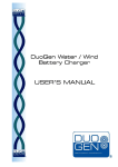
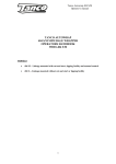
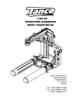
USER’S MANUAL
V2.2
6740 Cortona Drive
Goleta, CA 93117 USA
[email protected]
MULTI-PURPOSE DEVICE
(800) 235-5741
cmcrescue.com
Pulley l Descent Control l Belay
3330X0.00.101413
5. Let go of Release Handle immediately to activate belay!
M/A System
1.
2.
3.
4.
5.
Rig running end of rope through additional pulley(s).
Attach moving pulley to rope with rope grab.
Unlock Parking Brake.
Pull rope through M/A system.
MPD will hold rope during reset.
MULTI-PURPOSE DEVICE
USER’S V2.2
MANUAL
Pulley l Descent Control l Belay
Thank you for selecting the CMC Rescue MPD™ for your technical rope
rescue systems. Truly a multi-purpose device, the flexibility and versatility
of the MPD reduces the number of components in a rescue system and
simplifies system rigging. The result is a safer and more efficient rescue.
Please contact Customer Support if you have questions about this, or any
other CMC Rescue product.
WARNING
° Serious injury or death may result from the improper use of this equipment.
° This equipment has been designed and manufactured for use by experienced
professionals only.
° Do not attempt to use this equipment without proper training.
° Failure to follow these instructions could result in serious injury or death.
THIS DEVICE MEETS THE AUXILIARY EQUIPMENT (PULLEY, DESCENT
CONTROL AND BELAY DEVICE) REQUIREMENTS OF NFPA 1983,
STANDARD ON LIFE SAFETY ROPE AND EQUIPMENT FOR
EMERGENCY SERVICES, 2012 EDITION. EMERGENCY SERVICES
AUXILIARY EQUIPMENT IN ACCORDANCE WITH NFPA 1983-2012.
THIS MPD HAS PASSED THE MINIMUM BREAKING STRENGTH
AND HOLDING LOAD TEST USING THE FOLLOWING ROPE:
NEW ENGLAND ROPES, KMIII, CMC ITEM K05160, 13 mm
OR NEW ENGLAND ROPES, KMIII, CMC ITEM K05140, 11 mm
(AS APPLICABLE).
About the MPD
2
Release Handle
2
Parking Brake
4
Rigging the MPD
4
Securing the MPD
7
Using the MPD
as a Descent Control Device
8
To Lower
8
To Stop Lowering
11
Using the MPD as a Belay Device
12
Belaying a Lowering System
12
Belaying a Raising System
15
Mirrored Systems
15
Using the MPD in a
Mechanical Advantage System
16
Additional Information
17
(KMIII rope used for certification. For information on performance with other life safety
ropes, please contact CMC Rescue).
High Lines and Guiding Lines
17
Care and Maintenance
17
MADE IN THE USA (of US and foreign components).
Inspection and Repair
18
The most current version of the MPD User’s Manual can be downloaded
at cmcrescue.com/mpd.
Specifications
19
Quick Reference Guide
20
ISO 9001: 2008 Certified
©2013 CMC Rescue, Inc. All Rights Reserved.
1
CMC Rescue, Inc.
6740 Cortona Drive, Goleta, CA 93117 USA
(800) 235-5741 or (805) 562-9120
[email protected]
cmcrescue.com
2
THE MPD
The MPD is designed for use with static or low-stretch kernmantle life safety
rope. Use only rope that has been inspected, is of proper size and is in good
condition. The user should be aware that environmental conditions may
have an effect on the rope’s interaction with the MPD. For example, water
saturated ropes, icy ropes or ropes otherwise covered with substances such
as clay, tar or oil will, to varying extents, affect the rope’s interaction with the
MPD. The user should be aware of these conditions and make necessary
adjustments, such as adding additional friction. Saturated ropes or ropes
covered with foreign material may not progress smoothly through the MPD,
possibly resulting in a ratcheting type of progression as the rope moves
through the device. Additionally, rope that is dirty, sandy or muddy may
cause increased wear to the fixed and moving brakes, which may reduce
the device’s ability to arrest and hold a load.
RELEASE HANDLE
The Release Handle is used to rotate the Moving Brake off of the rope,
allowing rope movement through the device for lowering a load or releasing
tension on a line, such as with a guiding line or track line. Pulling the
Release Handle out engages a set of gears connected to the Moving Brake.
To minimize wear on the Moving Brake, it is recommended to turn the
handle fully counterclockwise to completely unseat the Moving Brake from
the rope and to control the rate primarily with friction of the rope applied
against the Fixed Brake V-Groove. To stop lowering and lock the rope,
disengage the Release Handle. NOTE Although there is a return spring to
assist in disengaging the Release Handle, it is the user’s responsibility to
ensure that the handle is fully pushed in when not actively lowering.
!
IF AT ANY TIME YOU NOTICE A SUDDEN CHANGE IN SPEED OR TENSION
ON THE ROPE RUNNING THROUGH THE MPD, IMMEDIATELY LET GO
OF THE RELEASE HANDLE (DISENGAGE) TO STOP THE LOAD!
Item Number 333000, 13 mm Rope Model
As with all new rescue equipment, the MPD should be thoroughly inspected
before being placed in service. The MPD is a robust unit but should still
be inspected after each use to ensure that damage did not occur. When
inspecting, look for any damaged, dirty or sticking components, excessive
wear or any other factor that may prevent proper function.
Front
Plate
Secondary
Friction Post
Front
Cover
Parking
Brake
Release
Handle
Back
Plate
Becket
High-Efficiency
Pulley with
One-Way Bearing
Fixed Brake
with V-Groove
Moving
Brake
3
Single
Pulley
Double
Pulley
Simple 3:1
M/A System
Simple 5:1
M/A System
ABOUT THE MPD
4
PARKING BRAKE
A unique feature of the MPD is the Parking Brake, which when locked,
prevents inadvertent letting out of the rope. The design of the Parking
Brake allows for rope to be taken in if required without having to unlock it,
although increased rope friction will be encountered. Lock the Parking Brake
prior to releasing your grip from the running end of the rope, except when
the MPD is rigged as a ratchet or progress capture in a pulley system. For
example, once the rigged MPD is connected to the anchor, for safety, lock
the Parking Brake until you are ready to use the device. To fully lock the
Parking Brake when using untensioned, icy or saturated rope, it may first be
necessary to pull out the Release Handle and rotate it clockwise to further
force the Moving Brake against the rope.
1
REVIEW DIAGRAM
FOR PROPER LOADING
2
ROTATE BACK PLATE
FULLY OPEN
Anchor
THE MPD
To rig the MPD, first ensure that the Parking Brake is unlocked. Hold the
MPD so that the back plate faces up. Take note of the diagram showing
the proper rope orientation, then open the MPD by rotating the back plate
clockwise until there is sufficient space to insert the rope between the fixed
and moving friction brakes.
Insert the rope with the running end between the friction brakes and place
the rope around the pulley in a clockwise direction. The load end of the rope
exits the pulley opposite the friction brakes. Close the MPD by rotating the
back plate completely counterclockwise, making sure that the rope properly
enters and exits the MPD as shown in the diagram on the back plate. Attach
the MPD to the anchor using an appropriate locking carabiner or screw link
through both the front and back plates.
INFORMATION
HIGH LINES AND GUIDING LINES
Running End
Running End
Load End
Load End
3
INSERT
ROPE
Parking Brake must be unlocked to load.
4
CLOSE AND SECURE
BACK PLATE
5
a fixed position of the friction
hand, while the other hand feeds
rope into the MPD.
!
Feed In Running End
FIRMLY GRIP RUNNING END OF ROPE TO ACTIVATE BELAY.
RIGGING THE MPD
6
THE MPD
!
NOTE The Parking Brake is intended to
temporarily secure the MPD when it is necessary
for the operator to release their grip on the
running end of the rope.
ALWAYS PERFORM A SAFETY
CHECK BY UNLOCKING THE
PARKING BRAKE AND GIVING
A QUICK TUG ON THE LOAD
END OF THE ROPE TO ENSURE
PROPER RIGGING PRIOR TO
COMMITTING A LIVE LOAD
OVER AN EDGE.
If the MPD is to be left unattended, or if you
need to release your grip on the running
end of the rope for more than a short
time, lock the Parking Brake first and
then secure the MPD by tying off the
running end of the rope around the
load end with an appropriate
tie-off method.
WHEN RIGGED PROPERLY,
THE MPD WILL LOCK UP.
THE MPD MUST BE
PROPERLY RIGGED
PRIOR TO USE.
Tug on
Load End
Running End
7
BELAYING A RAISING SYSTEM
If the load is being raised, then the Belay Line can simply be pulled hand
over hand through the MPD. However, if the distance the load has to be
raised is greater than approximately 30 m (100 ft), it is recommended to
convert the Belay Line system into a simple 3:1 mechanical advantage
properly disposed of after the operation is safely completed.
BELAYING A LOWERING SYSTEM
When belaying a lowering system, once the rescuer has good control of the
load and is in the correct descent path (this often occurs within the first
8
AS A DESCENT CONTROL DEVICE
When used to control a descent, the MPD design allows for easy adjustment
of the friction for the size of the load, rope type, and environmental and
terrain conditions. The speed of the descent is controlled by the friction of
the rope applied against the Fixed Brake V-Groove. Always start with the
running end held firmly back toward the anchor, parallel to the load end.
Reduce the friction by varying the angle at which the running end enters the
MPD. Maximum friction is applied when the Secondary Friction Post is used.
!
Begin lowering by rotating the handle slowly counterclockwise all the
way to completely unseat the Moving Brake from the rope, controlling
the rate primarily with friction on the Fixed Brake V-Groove. Maintaining
the “S-shaped” bend in the rope will improve the function of the braking
mechanism in the event it is needed and will increase the service life of
the Moving Brake, reducing the potential for rope creep through the device.
AT NO POINT SHOULD THE RUNNING END OF THE ROPE HAVE AN ANGLE
OF LESS THAN 90º TO THE LOAD END OF THE ROPE.
S-shaped bend
Edge transitions can be the most challenging part of an operation. Using the
MPD as a descent control device allows for a high degree of responsiveness
and control. As the rescuer or rescuer and patient approach the edge, it is
very easy to take in rope through the MPD to prepare for the edge transition.
Pretensioning of the Main Line is also simplified because of this.
Anchor
TO LOWER
To lower, firmly grip the running end of the rope and tightly hold it against
the Fixed Brake V-Groove, bringing it back toward the anchor and parallel to
the load end, creating an “S-shaped” bend in the rope as it passes through
the MPD. Pass the rope over the Secondary Friction Post for heavier loads if
needed. Unlock the Parking Brake and then firmly grip the Release Handle.
For the most comfortable hand operating position, before pulling outward on
the handle, give a slight clockwise turn of the wrist, then pull out to engage
the release mechanism.
Load
!
ALWAYS MAINTAIN A FIRM GRIP ON THE RUNNING END OF THE ROPE
DIRECTED BACK TOWARD THE ANCHOR IN AN “S-SHAPED” BEND BEFORE
ENGAGING THE RELEASE HANDLE.
9
10 m [33 ft] of the descent), it is recommended to convert from hand-tight
Belay Line tension to shared tension between the Main Line and Belay
Line. Should the Main Line system fail from this point on, a Shared Tension
system will minimize rope stretch and provide a considerably reduced
arresting distance as compared to a conventional untensioned belay. It
engage the
release
mechanism
(2)
Rotate counterclockwise
to lower
USING THE MPD AS A
DESCENT CONTROL DEVICE
10
FOR HEAVY LOADS
Add additional friction by threading the rope over the Secondary Friction Post.
PREPARING TO LOWER
Firmly grip the running end of the rope and apply friction over the Fixed
Brake V-Groove, bringing the rope back toward the anchor and parallel to
the load end, creating an “S-shaped” bend in the rope.
Load
Load
ALWAYS MAINTAIN AN “S-SHAPED” BEND IN ROPE
TO STOP LOWERING
TO LOWER
To stop lowering and lock the rope, disengage the Release Handle.
Unlock the Parking Brake. Grasp the Release Handle and pull up to
engage the release mechanism (1) and then rotate counterclockwise
to lower (2). Rotating the Moving Brake off the rope may significantly
increase the service life of the MPD.
NOTE Although there is a return spring to assist in disengaging the Release
Handle, it is the user’s responsibility to ensure that the handle is fully
pushed in when not actively lowering.
(1)
!
ALWAYS MAINTAIN A FIRM GRIP ON THE RUNNING END OF THE ROPE
WHEN THE PARKING BRAKE IS NOT LOCKED.
Pull up to
engage the
release
mechanism
(2)
Rotate counterclockwise
to lower
FOR HEAVY LOADS
Add additional friction by threading the rope over the Secondary Friction Post.
11
For the most comfortable hand operating position, before pulling outward on
the handle, give a slight clockwise turn of the wrist, then pull out to engage
the release mechanism.
12
AS A BELAY DEVICE
The MPD is designed to be used as a belay device to arrest a falling load
should the Main Line system fail. It is recommended that during edge
transitions, while either lowering or raising loads, that the Belay Line tension
be kept hand tight and without slack in the line. Stumbles by the rescuer or
litter tender(s) are most likely to occur during edge transitions, which may
result in the ropes being run across edges that can potentially damage or
cut them. It is less likely to damage both ropes if the Belay Line remains
untensioned during these transitions. Additionally, greater descent control
can be achieved if only one rope manages the rate of descent during edge
transitions.
If the Main Line system completely fails during an edge transition (e.g.
anchor failure or improper system connection), and if both ropes are
suspended above the terrain, as when using a high directional, then a
dynamic fall onto the Belay Line is likely. Among rescuers, this is widely
recognized as potentially the worst case dynamic event in rescue work.
While every effort should be made to rig and operate systems to minimize
the potential for such dynamic events, the MPD is designed and has been
tested to arrest a 1 m fall onto 3 m of static rope with a rescue-sized load
and limit the peak force below 15 kN (3,372 lbf) with no more than 1 m
(3.3 ft) stopping distance (as advocated by the British Columbia Council of
Technical Rescue Belay Competency Drop Test Criteria). Such a dynamic
event is severe and warrants that all involved equipment be retired and
properly disposed of after the operation is safely completed.
10 m [33 ft] of the descent), it is recommended to convert from hand-tight
Belay Line tension to shared tension between the Main Line and Belay
Line. Should the Main Line system fail from this point on, a Shared Tension
system will minimize rope stretch and provide a considerably reduced
arresting distance as compared to a conventional untensioned belay. It
will also help mitigate other hazards, such as an inadvertently slack Belay
Line or rope-induced rockfall, since the now-tensioned Belay Line will be
suspended above the terrain between contact points, just like the Main Line.
SHARED TENSION SYSTEMS
Shared Tension Systems are essentially two lowering systems in place of
one lowering system and a belay, with each line supporting approximately
half the load. If either system should fail, the increased load on the other
descent control device will cause an increase in rate of descent. While the
MPD is an effective belay device capable of safely arresting a falling load,
when used as a descent control device you are manually overriding the
belay function. This could result in increased stopping distances
if not using proper technique.
Therefore, in a Shared Tension lower it is imperative that the running end
rope of the Belay Line be held back toward the anchor, maintaining the
“S-shaped” bend as the rope runs through the MPD. If there is a sudden
change in speed or tension on the rope running through the MPD,
the belayer must immediately let go of the Release Handle
(disengage) while maintaining a firm grip on the running end of the
rope to ensure the braking mechanism activates and arrests the load
in the shortest distance possible.
!
YOU MUST LET GO OF THE RELEASE HANDLE WHILE MAINTAINING A FIRM
GRIP ON THE RUNNING END OF THE ROPE TO ACTIVATE THE BELAY!
BELAYING A LOWERING SYSTEM
When belaying a lowering system, once the rescuer has good control of the
load and is in the correct descent path (this often occurs within the first
13
Begin lowering by rotating the handle slowly counterclockwise all the
way to completely unseat the Moving Brake from the rope, controlling
the rate primarily with friction on the Fixed Brake V-Groove. Maintaining
the “S-shaped” bend in the rope will improve the function of the braking
mechanism in the event it is needed and will increase the service life of
Running End
USING THE MPD
AS A BELAY DEVICE
14
For the greatest system redundancy and therefore safety ensure the Belay
Line system is anchored and operated independently of the Main Line
system.
As with the Main Line, it is recommended that someone assist the Belay
Line operator by feeding rope to ensure there are no tangles or snags that
would cause the operator to unnecessarily stop the operation.
BELAYING THE EDGE TRANSITION
To ensure proper hand-tight tension of the Belay Line (such as during edge
transitions), firmly grip the load end of the rope with one hand and apply
friction, so that there is no slack in the rope between the load and your
hand. The other hand feeds the running end into the MPD so that the
rope is unseated from the sheave tread. This will reduce rope drag on
the sheave and keep the MPD from inadvertently locking up. This technique
allows the operator to match the speed of the Main Line. In contrast, the
technique of trying to simultaneously shuffle rope into and out of the MPD
will result in a repetitious start-stop motion of the belay rope and will likely
result in frequent unwanted lockups.
Applying Hand-Tight Tension
to the Belay Line
The operator is bracing his
arm on his leg to help maintain
a fixed position of the friction
hand, while the other hand feeds
rope into the MPD.
!
Load
NOTE The Parking Brake is intended to
If the load is being raised, then the Belay Line can simply be pulled hand
over hand through the MPD. However, if the distance the load has to be
raised is greater than approximately 30 m (100 ft), it is recommended to
convert the Belay Line system into a simple 3:1 mechanical advantage
pulley system to assist with the raising of the load. The load can be raised
more efficiently if the Belay Line assists with the raising, since it is possible
that a lower mechanical advantage will be required by the Main Line. This
will also take the stretch out of the line. For the final edge transition, convert
back to a 1:1 system using only hand tight tension on the Belay Line by
pulling it hand over hand through the MPD.
MIRRORED SYSTEMS
Rope rescue systems, where both rope systems are capable of
simultaneously performing as a Main Line and a Belay Line are referred
to as Mirrored Systems. Unlike the MPD, most descent control devices
are incapable of performing both functions concurrently. Ideally, a true
independent Mirrored System is achieved with maximum flexibility and
versatility when both the Main Line and Belay Line are each managed
with an MPD. This way either rope system can perform either function,
without the need for complex changeovers or function specific equipment.
Additionally, if an MPD is used for both the Main Line and Belay Line in a
Shared Tension System, then should either of these systems fail, the other
rope system can serve as a belay and the potential arresting distance is
minimized since both ropes will be prestretched.
Feed In Running End
FIRMLY GRIP RUNNING END OF ROPE TO ACTIVATE BELAY.
THE MPD
BELAYING A RAISING SYSTEM
15
the rope around the pulley in a clockwise direction. The load end of the rope
exits the pulley opposite the friction brakes. Close the MPD by rotating the
back plate completely counterclockwise, making sure that the rope properly
enters and exits the MPD as shown in the diagram on the back plate. Attach
the MPD to the anchor using an appropriate locking carabiner or screw link
through both the front and back plates.
16
IN A MECHANICAL ADVANTAGE SYSTEM
The MPD is designed to function both as a pulley and as a ratchet or
progress capture device in a M/A system. After lowering, there is no need
for a complex changeover between a lowering system and a raising system.
The one-way pulley inside the MPD applies friction during descent control
but serves as a fully functional, high-efficiency pulley while raising the
load. The MPD effectively locks the rope during pulley system resets with
minimal settling in distance. To convert to an M/A system, simply attach a
rope grab and traveling pulley to the Main Line and a simple 3:1 mechanical
advantage is created. The MPD has a built in Becket that can be used to
attach a change of direction pulley to allow higher mechanical advantage
systems to be built (e.g. simple 5:1 or compound 9:1), thereby eliminating
the need for a rigging plate. This keeps the pulley system neat and clean
with minimal loss of efficiency.
INFORMATION
HIGH LINES AND GUIDING LINES
The MPD was specifically designed to meet all required functions of a descent
control device, pulley with integral ratchet and belay device. As such, the MPD
is highly versatile for use in many aspects of high-line rigging, including:
• Guiding-line
or high-line track rope tensioning
management
• Operating the hoist or reeving lines
• Tag-line
For additional information on use of the MPD, instructional videos can be viewed at
cmcrescue.com/videos. Additionally, CMC Rescue School provides comprehensive,
hands-on training for all advanced techniques.
For questions or information on training with the MPD, or any other CMC Rescue
product, please call (800) 235-5741 or email [email protected].
CARE AND MAINTENANCE
Clean and dry the MPD after each use to remove any dust, debris or
moisture. Do not store the MPD with equipment where it may be exposed
to moist air, particularly where dissimilar metals are stored together.
Single
Pulley
Single
Pulley
Simple 3:1
M/A System
Double
Pulley
Simple 5:1
M/A System
User Information shall be provided to the user of the product. NFPA Standard
1983 recommends separating the User Information from the equipment
and retaining it in permanent record. The standard also recommends
making a copy of the User Information to keep with the equipment and
that the information should be referred to before and after each use. The
most current version of the MPD User’s Manual can be downloaded at
cmcrescue.com/mpd.
Additional information can be found in NFPA 1500, Standard on Fire Department
Occupational Safety and Health Programs and NFPA 1983, Standard on Life
Safety Rope and Equipment for Emergency Services.
17
disengage the Release Handle. NOTE Although there is a return spring to
assist in disengaging the Release Handle, it is the user’s responsibility to
ensure that the handle is fully pushed in when not actively lowering.
!
IF AT ANY TIME YOU NOTICE A SUDDEN CHANGE IN SPEED OR TENSION
ON THE ROPE RUNNING THROUGH THE MPD, IMMEDIATELY LET GO
OF THE RELEASE HANDLE (DISENGAGE) TO STOP THE LOAD!
ABOUT THE MPD
18
INSPECTION
Inspect the MPD according to your department’s policy for inspecting life
safety equipment. Equipment should be inspected after each use by an
inspector that meets your department’s training standard for inspection of
life safety equipment. Record the date of the inspection and the results in
the equipment log. Each user should be trained in equipment inspection and
should do a cursory inspection before each use.
The MPD should be inspected after each use to ensure that damage did not
occur. When inspecting, look for any damaged, dirty or sticking components,
excessive wear or any other factor that may prevent proper function. If any
significant damage is observed, the equipment should be retired from
service.
The MPD must be inspected after an impact load has occurred. Inspect for
any damage to the components. Evaluate the sheave for smooth operation
of the bearing. If any damage or indications of improper function are
noted, the MPD should be immediately retired from service.
REPAIR
All repair work shall be performed by the manufacturer. Other work or
modifications may void the warranty and shall release CMC Rescue, Inc.
from all liability and responsibility.
For information or service contact:
CMC Rescue, Inc.
6740 Cortona Drive, Goleta, CA 93117 USA
(800) 235-5741 or (805) 562-9120
[email protected]
cmcrescue.com
Item Number 333000, 13 mm Rope Model
UL Classified to NFPA 1983-2012 Edition
• Pulley General Use
• Descent Control General Use
• Belay Device General Use
Rope Diameter 13 mm* (1/2 in)
Weight 1.1 kg (2 lb 8 oz)
Rated Strength
• Pulley 44 kN (9,891 lbf)
• Descent Control 23 kN (5,170 lbf)
• Becket 33 kN (7,418 lbf)
13 mm Rope Model
Rope used for certification rounded up to 13 mm per NFPA 1983.
*Designed for use with 12.5 to 13 mm rope.
Item Number 333010, 11 mm Rope Model
UL Classified to NFPA 1983-2012 Edition
• Pulley General Use
• Descent Control Technical Use
• Belay Device General Use
Rope Diameter 11 mm (7/16 in)
Weight 1.1 kg (2 lb 8 oz)
Rated Strength
• Pulley 44 kN (9,891 lbf)
• Descent Control 20 kN (4,496 lbf)
• Becket 33 kN (7,418 lbf)
11 mm Rope Model
Photos used throughout this manual are Item Number 333000
MPD 13 mm Rope Model.
19
As with all new rescue equipment, the MPD should be thoroughly inspected
before being placed in service. The MPD is a robust unit but should still
be inspected after each use to ensure that damage did not occur. When
inspecting, look for any damaged, dirty or sticking components, excessive
wear or any other factor that may prevent proper function.
MADE IN THE USA (of US and foreign components).
The most current version of the MPD User’s Manual can be downloaded
at cmcrescue.com/mpd.
ISO 9001: 2008 Certified
©2013 CMC Rescue, Inc. All Rights Reserved.
20
REFERENCE GUIDE
Safety/Rigging
1.
2.
3.
4.
Read and refer to this manual.
Tug on load end of rope to verify correct rigging before use.
Lock Parking Brake when MPD not under load.
Lock Parking Brake and tie off MPD when left unattended.
Descent/Lowering
1. Hold rope firmly back against Fixed Brake V-Groove, maintaining
“S-shaped” bend in rope.
2. Add Secondary Friction Post for heavy loads.
3. Unlock Parking Brake.
4. Pull and turn Release Handle (full open).
5. Control speed with friction on Fixed Brake V-Groove.
Belay – Edge Transition
1.
2.
3.
4.
Hold load end of rope hand tight.
Unlock Parking Brake.
Feed running end of rope into MPD.
Maintain firm grip on running end to activate belay!
Belay – Shared Tension Systems
1. Hold rope firmly back against Fixed Brake V-Groove, maintaining
“S-shaped” bend in rope.
2. Unlock Parking Brake.
3. Pull and turn Release Handle (full open).
4. Control tension with friction on Fixed Brake V-Groove.
5. Let go of Release Handle immediately to activate belay!
M/A System
1.
2.
3.
4.
5.
Rig running end of rope through additional pulley(s).
Attach moving pulley to rope with rope grab.
Unlock Parking Brake.
Pull rope through M/A system.
MPD will hold rope during reset.
USER’S V2.2
MANUAL
About the MPD
2
Release Handle
2