1
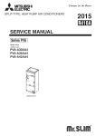
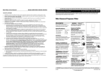
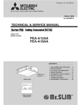
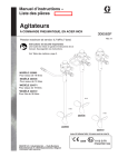
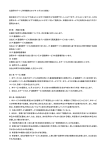
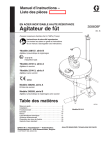
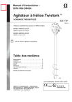
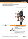
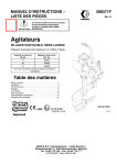
CG-550/030/A/GT/HP
MAINTENANCE & OPERATING INSTRUCTIONS
WITH
REPAIR PARTS LIST
SERIAL #______________________________
SAFETY DATA
PLEASE READ AND HEED THE FOLLOWING IMPORTANT SAFETY NOTICES BEFORE
PLACING MACHINE IN SERVICE.
* * * * NOTICE * * * *
PROPER PERSONAL PROTECTIVE EQUIPMENT, INCLUDING, BUT NOT LIMITED TO:
GOGGLES, DUST MASKS OR RESPIRATORS, GLOVES, HARD HAT, BOOTS AND RAINGEAR
MUST BE WORN WHEN OPERATING THIS EQUIPMENT.
* * * * NOTICE * * * *
FOLLOW MATERIAL MANUFACTURER’S INSTRUCTIONS FOR PROPER MATERIAL USE
AND RECOMMENDATIONS FOR SAFETY EQUIPMENT AND PROCEDURES.
* * * * WARNING * * * *
NEVER PUT HANDS OR TOOLS IN MIXERS OR PUMP UNLESS PRIMARY POWER SOURCE IS
SHUT OFF AND DISCONNECTED AND KINETIC ENERGY DISSIPATED. ON ELECTRICALLY
POWERED EQUIPMENT, USE PROPER LOCK OUT/TAG OUT PROCEDURES. FAILURE TO
OBSERVE THIS WARNING COULD RESULT IN SERIOUS PERSONAL INJURY AND/OR
DAMAGE TO THE MACHINE.
* * * * WARNING * * * *
NEVER ATTEMPT TO DISCONNECT OR OPEN THE COUPLING ON ANY PART OF THE PUMP
DISCHARGE SYSTEM WHILE PUMP IS IN OPERATION, OR IF THE DISCHARGE SYSTEM IS
UNDER PRESSURE FOR ANY REASON.
* * * * WARNING * * * *
NEVER OPERATE MACHINE WITHOUT THE VARIOUS GUARDS, SHIELDS AND OTHER
SAFETY EQUIPMENT WITH WHICH THE MACHINE WAS ORIGINALLY EQUIPPED IN PLACE
AND FUNCTIONAL.
* * * * WARNING * * * *
ALL ELECTRICAL CONNECTIONS MUST BE MADE BY A QUALIFIED ELECTRICIAN.
* * * * WARNING * * * *
HYDRAULIC COMPONENTS, INCLUDING, BUT NOT LIMITED TO VALVES, FITTINGS,
HOSES, MOTORS, RESERVOIR AND FILTERS MAY BE HOT. TO PREVENT INJURY, TOUCH
ONLY THE HANDLES PROVIDED. LET THE HYDRAULIC COMPONENTS COOL BEFORE
SERVICING THE EQUIPMENT.
®
WARRANTY STATEMENT
ChemGrout, Inc. warrants that equipment shall be free from defects in material, workmanship or
components.
The period of this warranty shall be limited to 90 days from the date of purchase and the extent
of ChemGrout's liability shall be limited to replacement of components that have been proven
faulty. No claims in excess of component replacement value will be recognized.
Specifically excluded from this warranty is normal wear resulting from the mixing and pumping
of abrasive slurries or damage to the equipment as a result of improper use.
SAFETY
Various guards, shields, grates and screens are provided over moving parts, such as: sheaves,
couplings, augers, paddles, belts, etc. to guard against injury to operators while the equipment is
in operations.
Warning stickers are provided to remind operators of the potential hazards.
Operators are advised to utilize appropriate personal safety equipment including, but not limited
to, saftey glasses or goggles, dust masks or respirators, gloves and / or rain gear and hard hats
when operating this equipment.
LIABILITY
It is understood and agreed that ChemGrout is relieved of any and all liability that may arise
from personal injury or damage to property as a direct or proximate result of the removal of
protective guards, shields, etc., the ignoring of warning signs and the lack of common sense
procedures.
®
TABLE OF CONTENTS
SECTION
SUBJECT
1.
GENERAL DESCRIPTION
2.
OPERATING INSTRUCTIONS
3.
GROUT SUGGESTIONS
4.
DIAGRAM & REPAIR PARTS LIST
5.
GROUT PUMP INSTRUCTIONS
6.
AIR MOTOR INSTRUCTIONS
®
SECTION 1
GENERAL DESCRIPTION
®
CG-550/030/A/GT/HP
GENERAL DESCRIPTION
The ChemGrout Model CG550/030/A/GT/HP is a pneumatically powered, skid mounted
cement grout plant specially designed and constructed for application in the geothermal
industry. The machine consists of one 70 gallon capacity vertical shaft paddle mixer and
one CG-030 single acting piston type grout pump. An oversize 6” diameter mixer
discharge gate facilitates discharge of thick mixes into a 50 gallon capacity hopper
situated directly above the pump. The grout pump is driven by a 8” diameter selfreciprocating cylinder, which allows the pump to produce discharge rates up to 16 GPM
and pressures up to 700 PSI. The extra large capacity hopper makes continuous
operation possible. A 30 gallon capacity water batcher (OPTIONAL) is installed over the
mixing tank to facilitate quick batching.
All pump components are assembled with horseshoe shaped pins making assembly
and disassembly for cleaning and maintenance easily accomplished with no special
tools required.
Simplicity of design and construction ensures years of dependable service with proper
and timely maintenance.
Dimensions: 76” X 31” X 51” (78” with water batcher.)
Weight: 750 lbs
®
SECTION 2
OPERATING INSTRUCTIONS
®
OPERATING INSTRUCTIONS
GENERAL
* * * * WARNING * * * *
NEVER PUT HANDS OR TOOLS IN MIXERS OR PUMP UNLESS PRIMARY POWER
SOURCE IS SHUT OFF AND DISCONNECTED. FAILURE TO OBSERVE THIS
WARNING COULD RESULT IN SERIOUS PERSONAL INJURY AND/OR DAMAGE TO
THE MACHINE.
SET-UP
In general, the most important factors in setting up are proximity to the work and access
to materials and water supply; consideration should be given to the disposal of waste
materials and wash-out residue.
It is always best to keep grout lines as short as possible to reduce pumping distances.
This is particularly important when pumping hard-to-pump materials, such as sanded
grouts and pre-blended materials.
The source of solid materials (cement, fly ash, sand, etc.) should be readily accessible
and an adequate supply of water should be available for mixing and clean-up.
When planning a project for high production rates, it is well to remember that the
greatest consumption of time occurs when charging the mixers. A proper set-up can
reduce this to a minimum.
START-UP
After set up, visually inspect that there are no foreign objects or old set up materials in
either the pump or the mixer(s), then make all necessary connections.
With operating levers, valves, or handles in either "NEUTRAL" or "OFF" position and the
primary power source turned OFF, fill the pump hopper with clear water. NOTE: It may
be necessary to elevate the discharge hose during this operation to prevent water
exiting through the ball valves.
®
OPERATING INSTRUCTIONS (cont'd)
Turn on the primary power source and observe that conditions are normal and machine
is ready to run.
Check each mixer for proper operation by running the mixer in both forward and reverse
directions, if unit is so constructed as to allow reverse direction.
Next, start the delivery pump to discharge the water that was previously introduced into
the pump hopper. This is an ideal opportunity to check the grouting system to determine
that all lines and hoses are clear and unobstructed. Pump condition may also be
checked at this time by testing discharge pressure.
When it is determined that all systems are normal, shut off the pump and drain the
water from the pump and all lines.
NOTE: Some pre-blended materials and some on-site mixes of sand and cement tend
to separate and clog the hoses upon contact with residual water. To prevent this
occurrence, it's a good procedure to mix and pump out a cement/water slurry prior to
mixing and pumping the production material, to lubricate the pump and hoses.
PRODUCTION
During the production phase of the work, monitor pump and mixer performance
continuously, being alert to any signs of abnormality.
Keep mixers free of material build-up, keep the outside of the machine clean, and keep
pump packing lubricated and just tight enough to prevent leakage. (Section 5)
CLEAN-UP
After disposing of excess production materials, carefully wash out mixer tanks, paddles
and baffles into the pump hopper and pump the resulting washout material through the
grout hoses to a suitable disposal site. Continue this operation until only clear water is
discharged.
It is advisable to drain all residual wash water from the pump and all hoses when
washout is complete.
CAUTION: NEVER RUN PUMP WITHOUT FLUID AS IT WILL CAUSE SEVERE
DAMAGE TO PISTON AND SLEEVE.
®
SECTION 3
GROUT SUGGESTIONS
®
Please note that the information contained in this section
is general in nature, and not specific to geothermal
materials, which possess their own unique characteristics
and preparation procedures.
®
MIXING AND PUMPING SUGGESTIONS
NOTE:
The suggestions offered herein are intended as an aid to help the operator identify
some of the factors that need to be taken into consideration when mixing and pumping
cementitious grouts. Because a wide variety of materials are available for many different
applications, it is incumbent upon the operator to become familiar with the specific
characteristics of the material he intends to use.
MATERIALS
Among the commercially manufactured materials available in today’s market are
materials for structural repairs, floor toppings, high strength non-shrink grouts, manhole
and sewer lining mortars and other specialty materials. Each of these materials has
unique characteristics, which must be well understood to insure a successful
application.
FLOW
In general, most materials need to be of a flowable or pourable consistency for
successful pumping. This means that if the material can be poured out of a pail or
bucket, it can likely be pumped. The exception to this requirement is repair mortars,
which tend to be mixed in a thicker consistency and require special pumping
techniques. Materials that contain aggregates pump best and perform best when the
consistency is kept to the lower range of pourable; that is, not too wet.
SETTING TIME
Some materials contain accelerating admixtures to reduce the setting time. This is
particularly true of repair mortars and other spray applied materials so that strength gain
can be fairly rapid. It is important to keep moving when using these types of materials.
Once the material is mixed, it must be pumped immediately and kept in motion and
subsequent batches must be mixed and pumped as rapidly as possible. Any delays in
the application process could result in plugged hoses and equipment. Temperature also
has an effect upon these materials to the extent that exposure of the hose to the sun on
a hot day will accelerate the set time even more; therefore this should be avoided. It
may even be necessary in some cases to cool the material, the mix water, or even the
hose itself.
PUMPING DISTANCE
Pumping distances should always be kept to a minimum, and hoses should run as
straight as possible no matter what material is being used. Sometimes circumstances
require longer than usual hose lengths; when this occurs, every effort should be made
to use every advantage possible to insure a successful application. Some materials
simply cannot be pumped for long distances, so it’s best to know the proposed material
characteristics before attempting a production procedure.
®
MIXING AND PUMPING SUGGESTIONS (Cont’d.)
GENERAL PROCEDURES
Before attempting to mix and pump production materials, it is prudent to rinse the mixer
and charge the pump hopper with sufficient water to thoroughly flush the pump and all
grout lines. This is to purge the grouting system of any residual materials or scale that
may exist. Once that is completed, remove the grout hose from the pump and drain out
all water by elevating one end, or by progressively elevating the entire hose, starting at
one end and proceeding to the other.
Next, mix a slurry composed of portland cement in approximate proportions of 6-1/2 to
7-1/2 gallons of water to one bag (94 lbs.) of cement, and pump this through the
grouting system. This is to remove any residual water from the hose, lubricating it for
the production material to follow. Now the production grout may be mixed and pumped
immediately behind the slurry mix, which is thus evacuated from the hose, and may be
retrieved in a bucket. Do not attempt to pump production material through a dry hose.
Finally, one last word about procedures. Occasionally, no mater how conscientious an
operator may be, a hose will get plugged. Once this happens, the only sure way to
remove the plug is to empty it of material. Beating on it with a hammer or running over it
with a vehicle will not usually be successful. A prudent operator will be prepared for
such eventuality by having readily available a sufficient length of small diameter stiff
tubing, hose or plastic pipe to which he can rapidly connect a water source and flush the
grout from the hose.
®
ADDITIONAL SUGGESTIONS
“HOMEMADE” GROUT
Sometimes commercially prepared grouts are not readily available, and in these cases it
may be necessary to formulate and produce the material on site. This can be done quite
successfully, but certain basic principles must be observed.
The resultant material should exhibit the following characteristics:
1. A stable suspension of solids that does not separate while at rest.
2. Color must be predominantly that of the cement used.
3. Fluid enough to pour from a container but not too wet. (Thick batter consistency or
thicker)
CEMENT
There are several types of Portland cements manufactured to satisfy a variety of
specific requirements, such as high early strength, sulfate resistance and other needs.
The most common of these is Type I Portland, and is that which is most frequently used
in the production of cementitious grout.
WATER
In most instances, the water to be used for the production of grout should be clean and
free of sulfates or other dissolved chemicals. If available, potable water is ideal. Since
the water to cement ratio is the most important factor in the quality of the material in its
final state, the water content should be kept to the minimum that will produce materials
with the characteristics listed above.
ADMIXTURES
Admixtures are available to modify and enhance the grout mixture. These include
plasticizers, water reducing agents, expansive agents, anti-washout ingredients, set
time modifiers and others. Each of these admixtures are designed to impart specific
properties to the grout. If used at all, they should be used only with a full understanding
of their effects, and only according to the manufacturers’ recommendations.
FLYASH
In some parts of the country, flyash (a byproduct of coal burning power stations) is
available. This material has often been used to enhance the properties of cementitious
grouts or, in some cases to reduce the cement fraction. Use of this material should be
approached with CAUTION, since ash from some sources have, in recent years, been
observed to cause FLASH SET in grout mixes. If the use of this product is anticipated,
trial mixes should be made to prove their applicability.
®
ADDITIONAL SUGGESTIONS (Cont’d.)
SAND
Sand is often used in grout formulations either to increase the volume of the material,
thus reducing the cost, or to act as an aggregate in the case of high-strength structural
grouts. If the use of sand is anticipated, several factors must be considered such as the
shape, size and gradation of the sand to be used. In general, the sand should be clean,
well graded and of rounded, natural shape. Angular particles such as those found in
manufactured sands should be avoided.
Of all of the considerations when anticipating the use of sand in a grout mixture
intended to be pumped, one of the most important is gradation. Gradation of a sand
sample is determined by a sieve analysis, which reveals the percentages of each
individual particle size of which the sand is composed. Laboratory tests and field
experience shows that some sand gradations will pump better than others, and some
will pump only with difficulty, if at all. Sample sieve analysis data is offered herein as a
guide to choosing sand that has a good chance of producing a strong, pumpable grout
mix.
Another factor to take into consideration when choosing a sanded grout over a slurry
grout is the volume, or amount of sand that can be used in the mix. This will vary as a
function of the gradation, but in general will usually be in the proportion of 1-1/2 to 2
times the cement content by VOLUME. In rare cases, it may be possible to exceed this
proportion, but caution should be exercised.
Grouting Sand Gradation Specifications
Sieve Size
% Passing
#8
#16
#30
#50
#100
#200
100
90-100
55-80
30-55
10-30
0-10
NOTE:
The suggestions above are primarily for conventional portland cement based grouts. It
is recognized that geothermal work utilizes special mixes, therefore, it is incumbent
upon the operator to learn the characteristics of the material he will be using.
®
U. S. Standard Sieve Numbers
100
3/8
4
8
16
30
50
100
200
0
10
90
Materials with gradation curves to the right
80
20
70
30
60
40
50
50
40
60
Materials with gradation curves to the left
of these limits usually are NOT pumpable.
30
70
20
80
10
90
0
10
5
1
0.5
Particle Size in Millimeters
®
0.1
0.05
100
0.03
Percent Retained by Weight
Percent Passing by Weight
of these limits usually ARE pumpable.
SECTION 4
DIAGRAM & REPAIR PARTS LIST
®
14 15
17
27A
17A
18
10 10A
21
22
19
23
19A 20
3 3A 3B
2
34
9
16
33
2A
31A
24
28 28A
7
32
25
29
31
26
1
6
CG-550/030/A/GT
CG-550/030/A/GT/HP
COMPONENT PARTS LIST
REF #
1
2
2A
3
3A
3B
6
7
9
10
10A
14
15
14*
15*
16
17
17A
18
19
19A
20
21
22
23
24
25
26
27A
28
28A
29
31
31A
32
33
34
PART #
63030A
21030SCN50
21030HOP50
846SLIDE
546GATEGASK
33TBC7112
06CYL8X7
84030RELIEF
06NAN5000N06
06M05
06M05A
046AMNRV11
04K208
04SM6AMAN
04SM6AMA-TK1
06LUB15
30SW050T
21WINBASE
21PADCPLGH
2130PAD
21PADBUSH
21PADPIN
2130BAGBKR
2130COV
84BBLV50
542VICT#77
33EV11/4ABR
21050REDUCE11/4
2130DUSTCOV
33AM13
06CRAP2
06NAF5000N010
06NAL5000N010
06FRL1
841BBALL
06NVSA-ALT
061/8CHECK
DESCRIPTION
Grout Pump
Hopper Screen
Hopper
6" Slide Valve Assembly
Discharge Gate Gasket
T Bolt Gasket Clamp
8” X 7” Air Cylinder
Grout Pressure Relief Valve
Exhaust Silencer
½” Muffler
Replacement Element
Mixer Air Motor (Gast)
Air Motor Repair Kit (Gast Motor only)
Alternate Air Motor (Ingersoll Rand)
Repair Kit (Ingersoll Rand)
¾” ASL Air Line Oiler
15:1 Gearbox
Gearbox Base
1” Paddle Coupling
Mixer Paddle
Paddle Bushing
Paddle Pin
Mixer Guard / Bag Breaker
Cover For 27" Mix Tank
Mixer Air Valve
2” Victualic Clamp
1-1/4” Part A Evertite Coupling
2” to 1 ¼” Reducer
Mixer Cover
1” Air Connection
30 Mesh Air Filter
1” Air Line Filter
1” Air Line Lubricator
1” Filter/Regulator/Lubricator Assembly
Pump Control Valve
Directional Control Valve
1/8” Brass Check Valve
* Machine may be equipped with Gast or I/R motor.
** Complete sets of warning labels are available upon request
®
SECTION 5
GROUT PUMP INSTRUCTIONS
®
13
15
26
17
20
18
5B
12
27
27
16
21
14
6A
5
10
3A
22
7A
3
10C
6
4
6A
3A
1A
2A
2
10E
9A
22
19
8
10B
9
11
3
10A
7
3A
4
2B
1
2A
3
CG-030/A/HP Parts Diagram
2C
CG-030/A/HP
COMPONENT PARTS LIST
REF.
1
1A
2
2A
2B
2C
3
3A
4
5
5A
6
6A
7
7A
8
9
9A
10
10A
10B
10C
10E
11
12
13
14
15
16
17
18
19
20
21
22
26
27
®
PART NO.
DESCRIPTION
21030REDUCER-02C
24030RBOLT
21050REDUCE11/4
542VICT#77
33EV11/4ABR
84030RELIEF
21030STAPLE
33EV3GASK
21030BALL
See Main Parts List
See Main Parts List
21030BALLSEAT3
21030RING
21030TEE
24030TBOLT
21030SLEEVE
21030CYLBKTA
21030CYLBKTAHP
07030PIST
21030PISTBP
21030PISTSP
21030PISTCUP
243/4X10JAMNUT
21030AIRADAPT
06NAN500N06
06FRL1
06NAR5000N010
06NAL5000N010
06NAF5000N010
841BBALL
33AM13
06CYL8X7
06CRAP2
06NVSA-ALT
06VR370
292160
061/8CHECK
CG-030 Reducer (3” X 2” Victaulic)
CG030 Reducer Bolt (3/8-16 X 3-1/3)
2” Victaulic X 1-1/4” NPT Reducer
2” Victaulic Coupling (With Gasket)
1-1/4” Part A Evertite Coupling
Grout Pressure Relief Valve
CG-030 Staple Pin
Coupling Gasket
2-5/8” Polyurethane Ball
Hopper
Hopper Screen
CG-030 Ball Seat
“O” - Ring For Ball Seat
CG-030 Tee
Hopper Ball Retainer (3/8-16 X 4-1/2)
CG-030 Sleeve
CG030 Air Cylinder Bracket
CG030 Air Cylinder Bracket Adapter
Piston Assembly (parts 10A to 11)
CG-030 Piston Backer Plate
CG-030 Piston Spacer Plate
CG-030 Piston Cup
Piston Nut
CG-030 Piston Adapter
Exhaust Silencer
1” Filter/Regular/Lubricator
1” Regulator
1” Lubricator
1” Filter
1” Ball Valve
1” Air King Fitting
8" Bore X 7" Stroke Air Cylinder
30 Mesh Air Filter
1” 2 Pos., 4 Way Dir. Ctrl. Valve
Air Bleeder Valve (directional control)
Pressure Gauge
1/8” Check Valve
030 GROUT PUMP
Maintenance
Daily - add oil SAE 10 or SAE 20 at (15) Drain filter (16).
Operation
Connect air line to (18) and grout line to (1). Pour 5 gallons water in hopper (5). Start
pump by opening valve (17) and pump out water. Disconnect and manually drain hose.
Reconnect grout hose. Begin mixing by introducing first water, then solid materials to
mixer. Mix until smooth and creamy, then discharge into hopper and begin pumping see IMPORTANT NOTICES below.
Cleanup
Pour water into (5) and pump until discharge is clear. Stop pump, disassemble, wash
and clean. Reassemble pump immediately when clean to prevent loss of parts.
Important Notices
Some pre-blended grouts not pumpable. Granular particles in grout must be well
graded. Maximum particle size in slurry 3/16" (.5 cm.). Grout mix must not be too wet.
See section on grout mix recommendations.
®
SERVICE GUIDE
PROBLEM
PROBABLE CAUSE
SOLUTION
Pumps water O.K., will
not pump grout.
Grout mix too "thick", does
not enter pump chamber
Add water to grout mix, but
be careful not to dilute mix so
Much as to cause aggregate
to segregate.
Aggregate too large,
prevents
ball from seating.
Change to smaller
aggregate, or screen out
larger particles.
Aggregate segregations in
Discharge hose. (“Sand
Plugs”)
Drain residual water from
Discharge hose prior to
pumping grout.
Aggregate improperly
graded;
change aggregate.
Grout material has
excessive Coefficient of
internal friction.
Some premixed grout
materials are not pumpable.
See section on grout mix
recommendations.
Pump stalls on discharge
stroke.
Pump discharge or hose
plugged with grout.
Disconnect discharge hose,
check pump, clean out hose.
Pump runs but does not
discharge.
Grout not entering pump
Chamber.
Grout too "thick" or
obstruction in hopper.
Piston will not reverse
direction
Directional valve spool
“stuck”
Shift spool manually with
small diameter object, such
as a nail or awl.
Pump strokes unevenly
or too slowly.
Misadjusted shuttle valve.
Readjust shuttle valve
adjusting screws (13); turn
out to increase speed and in
to decrease speed.
®
SERVICE GUIDE cont’d
PROBLEM
PROBABLE CAUSE
SOLUTION
Pump does not run.
Insufficient air supply.
Check air at source.
Require
30 CFM at 100 PSI.
Pump fluid end plugged.
Remove staples (3),
disassemble pump and
check sleeve (3) for
obstruction.
Directional valve spool
“stuck”
Shift spool manually with
small diameter object,
such as a nail.
Obstruction in air supply
line or filter
Disconnect air line,
determine clear. Remove
cover and clean air filter.
Low discharge
Low air pressure.
Check air supply pressure;
pressure. Should be 100
PSI.
Grout or fluid leakage
around piston.
Excessive clearance
between piston and
sleeve.
Replace piston cups
Excessive piston wear
Dirty or scored sleeve.
Clean residual material
from sleeve (8), or replace
sleeve, if scored.
®
EXPLANATION OF AIR CYLINDER TIMING SEQUENCE DIAGRAM
VALID FOR CG-030 AND ALL AIR DRIVEN RECIPROCATING PUMPS
FIGURE 1
In this picture, air is entering the cylinder through Port B, driving the piston forward,
while exhaust air is exiting from Port A through the timing valve (1). While in motion, the
air pressure at pilot ports (4) and (5) is equal to line air pressure.
FIGURE 2
In Figure 2, the piston has traveled to its fully extended length and engaged poppet
valve (2), allowing the escape of a small amount of air from the pilot system. Release of
this air has reduced the air pressure at timing valve pilot port (5), resulting in a pressure
imbalance, causing the timing valve spool to shift, directing drive air through Port A,
reversing direction of piston travel.
FIGURE 3
As the piston rod retracts, air pressure in the pilot system is again equal to line
pressure, and exhaust air is expelled from the rear of the cylinder through Port B while
drive air is entering the cylinder through Port A.
FIGURE 4
The piston has reached its maximum retraction travel and engaged poppet valve (3),
resulting in a reduction of air pressure at pilot port (4). This causes the timing valve
spool to shift, directing drive air to the cylinder through Port B. The piston is now moving
forward again as exhaust air exits the cylinder through Port A.
®
TIMING SEQUENCE DIAGRAM
CHEMGROUT AIR POWERED PISTON AND PLUNGER PUMPS
2
2
3
3
A
(+)
A
Fig. 1
4
A
B
B
(+)
(+)
Fig. 2
5
1
3
A
B
(-)
A
B
1
2
B
(-)
4
A
4
2
Fig. 4
B
3
A
(+)
5
®
B
( +)
Fig. 3
4
1
5
A
B
(+)
5
1
SECTION 6
AIR MOTOR INSTRUCTIONS
®
AIR MOTOR
Operating and Maintenance Instructions
Construction
Your air motor is a precision built rotary type motor. The vanes will last 5,000-15,000
hours depending upon speed, method of oiling, operating pressure, and the precautions
taken in maintaining the motor. The type of shaft seal used does not lend itself to
operating pressures above 100 PSI.
Guarantee
Air motors are guaranteed against defects in material or workmanship (normal wear of
parts excluded) for a period of one year from factory ship date. Unit failing within
warranty will be rebuilt or replaced at manufacturer's discretion, F.O.B. factory.
Maximum liability not to exceed original purchase price of unit involved. Allowing excess
moisture or foreign particles from the air line to enter the motor will nullify the guarantee.
Installation
Install a moisture trap and filter in the air line ahead of motor. For efficiency of output
and control of speed, use air lines the same size as or the next pipe size larger than the
intake port of the motor. If operating intermittently without automatic air line oiler place
motor in accessible position for easy lubrication. A single rotation motor will operate
properly in only one direction. A reversible motor will work equally well in both
directions. A 4-way valve which can be connected by piping to both air ports of the
motor will make reversing possible. When coupling or connecting the motor to a driven
member, avoid any end or side thrust on the shaft, and especially do not hammer on
shaft.
Operation
The starting torque is less than running torque and could vary depending on the position
at which the vanes stop in relation to the air intake port. The speed and torque can be
regulated by using a pressure regulator or a simple shut-off valve to obtain desired
power and conserve air. For moderate speeds (under 2,000 RPM) or intermittent
operation 1 squirt of oil in bearing oilers per day will suffice. For continuous duty or
frequent high speed operation, use an automatic air line oiler set to feed 1-3 drops per
minute. The bearings will receive oil from the rotor chamber during automatic oiling.
Use SAE No. 10 oil. Lubrication is necessary for the bearings, shaft seals, and rust
prevention.
Excessive moisture in the air line can cause rust formation in motor and might also
cause ice to form in muffler due to expansion of air through the motor. The moisture
problem can be corrected by installing a moisture separator in the line and also by
installing and after cooler between the compressor and air receiver.
®
Servicing
If the motor is sluggish or inefficient try flushing with solvent* in well ventilated area.
Disconnect the air line and muffler and add several teaspoons full of solvent* Rotate the
shaft by hand in both directions for a few minutes, again connect the air line and apply
pressure slowly until there is no trace of solvent* in exhaust air. (Keep face away from
exhaust air). Check the muffler felts for grease, dirt, etc. If dirty, wash them in solvent.
Replace the felts and connect the muffler. Re-lubricate the motor with a squirt of oil in
the chamber and bearings oilers.
If the vanes need replacing, or foreign particles are present in motor chamber, an
experienced mechanic may remove the end plate opposite the drive shaft end. Don't
pry with a screw driver as it will dent the surface of the plate and body causing leaks. A
puller tool should be used which will remove the end plate while maintaining the position
of the shaft. New vanes should have the edge with corners cut on angle or the notched
edge (if reversible) towards the bottom of the vane slot. New gaskets should be the
proper thickness onion skin otherwise motor will operate inefficiently and waste air. The
end plates should be replaced carefully using an arbor press with a pusher acting on
both races of the bearing while supporting the opposite (drive) end of the shaft rigidly.
This will eliminate brinelling of the bearings and misalignment of rotor.
*Recommended solvent for air motors and lubricated pumps is Gast Flushing Solvent
part #AH255, or any non toxic, non flammable industrial cleaning solvent.
DO NOT USE KEROSENE.
®
SPECIAL INSTRUCTIONS
AIR OPERATED EQUIPMENT
Whenever compressed air powered equipment is used, it is the air compressor which is
the primary motive force to drive the equipment. Whether the compressor is driven by a
diesel or gas engine, or an electric motor is immaterial. The important factor is its
capacity to provide a sufficient QUANTITY of air expressed in terms of CUBIC FEET
PER MINUTE at a specific PRESSURE, usually expressed in terms of POUNDS PER
SQUARE INCH. Thus, compressors are usually rated in terms of X CFM at Y PSI. (For
example, 250 CFM at 120 PSI) Occasionally, you may see a horsepower rating, but it
is much more common for compressors to be rated as previously described.
In any event, the capacity to do work is directly related to the VOLUME and
PRESSURE of the compressed air supply. Air powered equipment is designed to
accomplish specific tasks and therefore, requires a specific MINIMUM VOLUME of
compressed air at a specific PRESSURE.
With any air powered equipment, it's perfectly acceptable to use a compressor with a
higher volumetric capacity than the equipment requires, since the equipment will only
use the amount of air that it needs; however, the stated pressure capacity of the
equipment should not be exceeded by more than 10%. Excess pressure can be
harmful to the seals of air motors and cylinders and will significantly shorten the service
life of the equipment.
Attempts to run pneumatically powered equipment on compressors of lower capacity
than required will likely yield disappointing results.
RECOMMENDATIONS
When using air powered equipment, some simple rules and procedures will help assure
a successful job:
1.
Keep compressor properly serviced with adequate fuel and engine oil and keep
compressor oil at proper levels. Drain condensation from receiving tank before
start-up.
2.
Keep hose runs between compressor and machine as short as practical.
3.
Use air hose that is rated for the pressure capacity of the compressor and of
sufficient diameter to transport the volume of air that the compressor is rated to
deliver. (In other words, use a BIG hose!)
4.
Never use air supply hose for any other purpose, and always
blow the hose out before connecting to equipment at the start of a working shift.
®
Recommendations For Air Operated Equipment (cont'd)
5.
Keep equipment and line oilers full and clean filters and mufflers daily. The
object is to provide an unrestricted flow of air TO and FROM the machine; move
it from the compressor to the machine as fast as possible, and when you're
finished with it, get rid of it as fast as possible. Also, remember that everything
needs lubrication, including air motors and cylinders, so keep the oilers full.
6.
One final word: in temperate geographical zones, work is often done in
temperatures between about 40 degrees F. and 60 degrees F. with relative
humidity that may reach as much as 100 percent. Because air is heated as it's
compressed and cools rapidly as it expands (like at the exhaust muffler of your
grout plant), be on the lookout for ice. Since the expanding moist air can cool to
temperatures below the freezing point, ice will frequently form around the
exhaust ports of air motors and cylinders; when this happens, a restriction is
created that may severely impair the operation of the equipment.
The introduction of an Anti-freezing agent such as "Tannergas" through special
dispensers made for that purpose is the best way to prevent ice formation under these
conditions. If this isn't available, obtain and install an additional line oiler immediately
after the compressor and keep it filled with ethylene glycol anti-freeze.
®