1
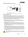
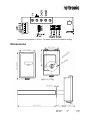
Installation manual
CF5-D, CF5-D-Disp
CO2 / temperature transmitter for mounting in
ventilation ducts
2
1
2
1
3
7
4
5
6
9
10
8
Figure 1
1
2
3
4
5
Sampling probe
Sealing gasket
Largest locking nob
2 washers
2 screws
6 O-ring 29,2x3,53 (Factory supplied mounted in box)
7 PCB (Factory supplied mounted in box)
8 Snap-in lid
9 PG9 cable entry bushing
10 Temperature sensor (to be put into the sampling tube)
Dokument
IMA 207
Rev
2
Page
1 (4)
Mounting of CF5-D on to the duct.
11
10
Figure 2
10
Hole with 25 mm diameter
11
Temperature sensor with 110 mm cable mounted in the sampling probe
Mounting Instruction
Since there might be a substantial pressure difference in duct mounting applications,
it is essential to avoid ambient air from suction into the duct mounting box. For
correct function it is indispensable that the sealing of the box cover, the cable entry
bushings, the cable feed through and the duct entrance are absolutely tight. The duct
entrance may need extra sealing paste in order to prevent leakage. The PCB must
be handed carefully and protected from electrostatic discharge.
1) Electrical cable entry: The box has a factory mounted cable entry bushing in
dimension PG9. Never feed more than one cable through each cable entry
bushing, or else gas might leak through!
2) Mounting the tube: Drill a hole (10) with 25 mm diameter (or 1 inch) for the
sampling probe and two holes with 4 mm diameter for the screws (5) into the air
duct and mount the tube (1) with the gasket (2). The sampling probe should be
mounted with the largest locking knob on top. The unit can be mounted with the
air coming from the left or right.
3) Attaching the sensor box is made to the sampling probe by a snap-in bayonet
fitting. First, carefully stick the temperature probe (11) into the sampling probe.
(1). Orient the box onto the sampling probe so that the box upside is on the same
side as the largest locking knob (3). When the probe is fitted into the notches of
the box, then turn the box clockwise until stop (see Figure 1). Position 1 indicates
open where the box can be removed from the sampling probe. In position 2 the
box is locked to the probe.
If for some reason the PCB must be removed it must be handed carefully
and protected from electrostatic discharge! Normally, removing the PCB is
not required.
Dokument
IMA 207
Rev
2
Page
2 (4)
Electrical connections
~
The power supply has to be connected to + and
.
is considered as system
ground. If the analogue output is connected to a controller the same ground reference
has to be used for the CF5-D unit and for the control system! Unless different
transformers are used, special precautions need to be taken.
PLEASE NOTE! The CF5-D signal and power supply
grounds are common.
NOTE! The same ground reference has to be
used for the CF5-D unit and for the control
system!
Connect the power after mounting. The analogue
output should be connected before measuring.
Connection
Terminal
~
+
Function
Power (+)
Electrical Data
Remarks
24 VAC/DC+ (+-20%), 3W 2W without output load
See note 1!
Power ground (-)
24 VAC/DC-
Out(1)
Analogue Output 1 (+)
0-10 VDC or 0-20 mA,
2-10 VDC or 4-20 mA,
According to positions of
Out(1) and start point
jumpers.
See note 2!
Out(2)
Analogue Output 2 (+)
Same as Output 1
According to positions of
Out(2) and start point
jumpers.
See note 2!
Not marked
Signal Ground (-)
Connected to
fuse
via PTC See note 1!
Note 1: The ground terminal is used as negative power supply DC input or AC phase
ground
(halfwave rectifier). The signal ground M, protected by a PTC resistor, is the
same as power ground
(permitting a ”3-wire” configuration). A single transformer may be
used for the entire system.
Note 2: CF5-D can deliver a voltage or a current loop for Out(1) / Out(2). To change
between voltage and current output mode the hardware jumpers are used. There is one
jumper for Out(1) and one for Out(2), so that one output can be a voltage output and the
other a current output. Both, voltage output and current outputs, can have start points 0 % (010 VDC or 0-20mA) or 20% (2-10 VDC or 4-20mA). The same start point is used for both
outputs. See the user manual.
Dokument
IMA 207
Rev
2
Page
3 (4)
+
~
Terminals and jumpers on CF5-D. The darker positions are default settings.
Dimensions
Dimensions of sensor in mm and inches
Dokument
IMA 207
Rev
2
Page
4 (4)