1
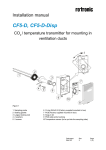
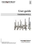
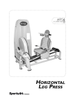
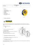
Installation manual
CF5-W, CF5-W-Disp
Dismounting of the sensor
4
1
3
2
1 top part
2 front part
3 wall plate
4 screw
5 label with
settings
inside the
top part
5
Pull the top part upwards
1
Push the front part upwards while
keeping the wall plate steady
UK Distribution by IMA Ltd:
Phone: +44 (0)1943 878877
Email: [email protected]
Web: www.ima.co.uk
Fold the front part forwards and
loose it from the hooks (#1)
Dokument
IMA 206
Rev
1
Page
1 (4)
Mounting of the sensor
A
B
The wall plate is screwed onto the wall (A) Put the top tabs of the front part into the top
holes of the wall plate.
(B) Press the lower edge of the case onto
the wall plate to latch
If the connection cables are drawn through a conduit the conduit must be
sealed.
Air of different temperature may otherwise disturb the temperature
measurements.
The screw head diameter should be max 7,5 mm
The screw head height should be max 2,5 mm
+
~
The top part is pushed under the
locking hooks of the wall plate
and is secured with a screw
Terminals and jumpers on CF5-W.
The darker positions are default settings.
Terminals and jumpers are located under the top part.
If for some reason the PCB must be removed it must be handed carefully
and protected from electrostatic discharge! Normally, removing the PCB is
not required.
Dokument
IMA 206
Rev
1
Page
2 (4)
Electrical connections
~
+
The power supply has to be connected to
and
.
is considered as
system ground. If the analogue output is connected to a controller the same ground
reference has to be used for the CF5-W unit and for the control system! Unless
different transformers are used, special precautions need to be taken.
PLEASE NOTE! The CF5-W signal and power supply
grounds are common
PLEASE NOTE!
The same ground reference has to be used for
the CF5-W unit and for the control system!
If possible keep the sensor powered up after mounting. Connect the analogue output
before measuring.
Connection
Terminal
Function
Electrical Data
Power (+)
24 VAC/DC+ (+20%), 3W
Power ground (-)
24 VAC/DC-
Out(1)
Analogue Output 1 (+)
0-10 VDC or 0-20
mA,
2-10 VDC or 4-20
mA,
According to positions of
Out(1) and start point
jumpers. See note 2!
Out(2)
Analogue Output 2 (+)
Same as Output 1
According to positions of
Out(2) and start point
jumpers. See note 2 and
3!
~
+
Not marked
Signal Ground (-)
Connected to
PTC fuse
Remarks
2W without output load
See note 1!
via
See note 1!
Note 1: The ground terminal is used as negative power supply DC input or AC phase
ground
(half wave rectifier). The signal ground M, protected by a PTC resistor, is the
same as power ground
(permitting a ”3-wire” configuration). A single transformer may be
used for the entire system.
Note 2: CF5-W can deliver a voltage or a current loop for Out(1) / Out(2). To change
between voltage and current output mode the hardware jumpers are used. There is one
jumper for Out(1) and one for Out(2), so that one output can be a voltage output and the
other a current output. Both, voltage output and current output can have start points 0 % (010 VDC or 0-20mA) or 20% (2-10 VDC or 4-20mA). The same start point is used for both
outputs. See the function manual.
Dokument
IMA 206
Rev
1
Page
3 (4)
Note 3: Please use voltage outputs for temperature measurements. The accuracy of temperature
measurements is valid only for units configured in voltage outputs mode.
Dimensions and holes
31(1,22)
83(3,26)
120(4,72)
Dimensions of sensor in mm and (inches)
30(1,18)
30(1,18)
Mounting of the sensor onto
the wall
25(0,98)
Please use screws with screw
head diameter less than 7,5
mm (0,295 inches) and screw
head height less than 2,5 mm
(0,1 inches)
52,5(2,07)
30(1,18)
2(0,08)
7,8(0,31)
29,8(1,17)
4,2(0,16)
Dimensions of mounting plate in mm and (inches)
Dokument
IMA 206
Rev
1
Page
4 (4)