1
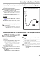
Connecting to the Network Provider
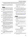
Cable with two Cable with star quad
twin wires
Physical
circuit/
pair 1
Physical
circuit/
pair 2
a1
Red
Without ring
b1
Black
Single rings, 17 mm spacing
a2
White
Double rings, 34 mm spacing
b2
Yellow
Double rings, 17 mm spacing
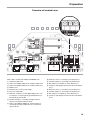
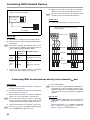
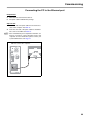
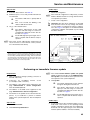
Abb. 16: Wire up the NT and the external S0 port
External S0 port
2. Connect the NT to the four terminal clamps on the external S0 port. See Abb. 16.
NT
☞
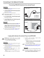
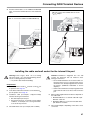
Connect the DSL connection to the Ethernet port
Important: If you would like to integrate the PBX into
an existing network, please contact the system administrator responsible for this. Making changes to an
existing network may cause considerable malfunctions. In addition, please note the PBX factory settings for the Ethernet configuration described in
Page 31.
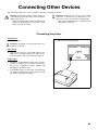
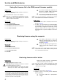
Abb. 17: Connecting the DSL router
Requirements
✔
Minimal distance between the devices
✔
A DSL router that is specifically designed for VoIP
data communication (SIP aware)
☞
✔
Note: If this is not the case, several of the ports on the
router necessary for VoIP data communication must
be enabled (RTP port and SIP-UDP ports) (Port Forwarding). A list of the ports used in the PBX can be
found in the configuration manager on the PBX under
Administration 왘 Port overview.
The patch cable included in the package
Steps to take
1. Insert the end of the cable into the Ethernet socket on
the PBX. See Abb. 17.
2. Insert the other end of the cable into the output socket
on the DSL router or into an existing network outlet.
☞
Note: To connect the DSL router to the network provider, please refer to the documentation provided by
the network provider and included with the DSL router. See also Abb. 11 and Abb. 12 on page 18.
Further steps
쑱 Configure the necessary network settings on the DSL
router and/or on the PBX at the end of commissioning. See Page 31.
21