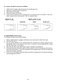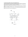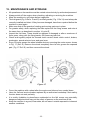
1
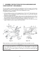
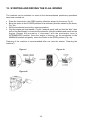
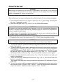
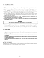
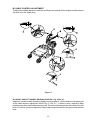
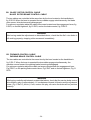
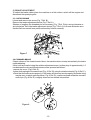
MIDLAND POWER DISTRIBUTION LIMITED qu alit y se r vic e suppor t FLM60H User Manual www.midlandpower.co.uk - FLAIL MOWER MANUAL CONTENTS 1. 2. 3. 4. 5. 6. 7. 8. 9. 10. 11. 12. 13. 14. 15. 16. 17. 18. 19. 20. 21. 22. USE OF THE MANUAL............................................................................pag. 4 NOTICE ON THE MACHINE..................................................................pag. 5 TECHNICAL DATA...................................................................................pag. 8 LIFTING AND TRANSPORTATION...........................................................pag. 9 MAIN PARTS OF THE MACHINE..........................................................pag. 10 CONTROLS AND ADJUSTMENTS.......................................................pag. 12 ASSEMBLY INSTRUCTIONS FOR THE HANDLEBARS AND FRONT SUPPORT WITH WHEELS......................................................pag. 14 SAFETY INFORMATION A) GENERAL INSTRUCITONS..............................................................pag. 15 B) TRAINING..........................................................................................pag. 15 C) PREPARATION.................................................................................pag. 15 D) WORKING USE.................................................................................pag. 16 E) AFTER WORK...................................................................................pag. 17 TRANSPORTATION OF THE MACHINE.................................................pag. 18 SAFETY SYSTEMS AND GUARDS.........................................................pag. 19 OPERATIONS TO BE CARRIED OUT BEFORE SWITCHING ON........pag. 19 STARTING AND DRIVING THE FLAIL MOWER..................................pag. 20 CUTTING TIPS......................................................................................pag. 22 CHECKS A) TYRE PRESSURE............................................................................pag. 22 B) CABLE CONTROL ADJUSTMENT....................................................pag. 23 C) BRAKES ADJUSTMENT...................................................................pag. 25 D) BELT REPLACEMENT AND ADJUSTMENT.....................................pag. 26 E) CHECKING AND REPLACING THE FLAILS......................................pag. 29 F) SHARPENING THE FLAILS.................................................................pag. 30 G) CHECKING AND REPLACING THE TRANSMISSION OIL...................pag. 31 MAINTENANCE AND STORAGE..........................................................pag. 32 CLEANING THE MACHINE....................................................................pag. 33 SEASONAL LONG-TERM STORAGE PERIODS..................................pag. 33 DECOMMISSIONING AND SCRAPPING................................................pag. 34 TECHNICAL ASSISTANCE......................................................................pag. 34 WARRANTY..............................................................................................pag. 34 CE MARKING........................................................................................pag. 35 TROUBLESHOOTING............................................................................pag. 36 Enclosure 1. NOTES Enclosure 2. Declaration of Conformity -3- Operating and Safety Instruction FLAIL MOWER MOD. 610 FOREWORD This machine may only be utilized for the purpose for which it was designed, i.e. agricultural use, for the cutting of shoots, grass and brushwood. Any other use other than that stated, not covered or deducible from this Manual and the enclosed Engine Manual is "PROHIBITED". Failure to comply with instructions in this Manual and in the Engine Manual releases the manufacturer from all liability, in particular for any damage resulting from improper or incorrect use, through negligence, superficial interpretation or flagrant disregard for the safety requirements herein. Get your dealer to explain how to use the machine in optimum safety conditions. Always perform the checks as prescribed herein before each work session with the machine. Should any information given in the following pages be unclear or not straightfor-ward please contact the manufacturer directly. 1. USE OF THE MANUAL This Manual consists of numbered pages and enclosures featured in the list of contents. Before operating the machine the user must read the instructions in the Operator's Manual caRefully as well as those of the Engine Manual enclosed. Use of the flail mower by more than one operator (individually), means that they must have carefully read the Operator's Manual and the Engine Manual before using it. The aforementioned manuals form an integral part of the machine and must therefore be kept intact and in good condition, in a known, easily accessible place for the entire working life of the machine, even if the flail mower is passed on to another owner. The purpose of these manuals is to provide the information necessary for the safe and competent use of the product. In the instance of wear or purely for a greater technical working knowledge, the manufacturer may be contacted directly. The Notes Section at the end of the Flail mower Manual is for the addition of any complementary notes. In this Manual all safety information appears in special boxes headed “WARNING”. WARNING This heading is used to draw the user's attention to hazardous areas or moving parts of the machine. It is also used in instances where failure to comply with the instructions given may result in injury to persons and animals or damage to property. -4- 2. NOTICE ON THE MACHINE The symbols affixed to the machine serving to warn of danger during its use and maintenance are as follows: THE USER MUST READ THE INSTRUCTION MANUAL PROVIDED DANGER OF FOREIGN OBJECTS BEING THROWN OUTWARDS. KEEP A SAFE DISTANCE ALWAYS DISCONNECT THE CABLE FROM THE ENGINE SPARK PLUG. DANGER OF HAND INJURY. SWITCH OFF THE ENGINE -5- DANGER OF CRUSHING. KEEP A SAFE DISTANCE DANGER OF INJURY TO BOTH UPPER AND LOWER LIMBS. DO NOT PUT HANDS OR FEET INSIDE THE CUTTING ELEMENT WHILE IN MOTION DANGER OF GETTING CAUGHT UP IN ROTATING PARTS. DO NOT PUT HANDS IN THE ROTATING PARTS DANGER OF FOREIGN OBJECTS BEING THROWN OUTWARDS. SAFETY GOGGLES MUST BE WORN -6- EAR DO NOT ALLOW CHILDREN NEAR THE MACHINE WHEN IN OPERATION.MUFFS MUST BE WORN CAUTION: HOT PARTS. DANGER OF BURNS. FIRE HAZARD The symbols affixed to the machine serve to warn of danger during its use and maintenance. It is vitally important to understand the meaning of the danger notices and all messages should be kept in legible condition. In the instance of wear these no-tices should be replaced and use of the machine suspended while without such notices. The operator is advised to observe the warnings given on the affixed notices. -7- 3. TECHNICAL DATA OF THE MODEL 610 ENGINE: petrol HONDA GX 200 K1 ENGINE CAPACITY: 4.8 kW (6.5 HP) ENGINE FILTER: dry filter WORKING WIDTH: 60 cm CUTTING HEIGHT: adjustable 20 - 80 mm CUTTING SYSTEM: 32 flail rotor SPEED GEARS: 2 forward gears – 2 reverse gears TRASMISSION: mechanical GEARS: in oli bath SPEED: forward (1) 1.80 km/h (2) 3.30 km/h reverse (1) 1.80 km/h (2) 3.30 km/h WHEEL RELEASE MECHANISM: mechanical START: recoil SERVICE BRAKE : on wheel axle ROTOR BRAKE : on rotor drive HANDLEBARS: height-adjustable TYRES: Tractor 13 x 5.00-6 SIZE L x W x H (mm): 1400 x 660 x 800 WEIGHT (kg): 120 ACOUSTIC PRESSURE, measured according to EN 12733 : ACOUSTIC POWER, measured according to EN 12733 : HANDLEBAR VIBRATION ( EN 12 733) AW : 89 dBA LWA 98 dBA 1,88 m/s² Environmental conditions Unless otherwise stated at the time of ordering it is understood that the machine is to work normally in the environmental conditions covered by the following points. Environmental conditions other than those described may cause mechanical breakage resulting in the creation of dangerous situations for persons. -8- ALTITUDE The altitude of the place in which the machine is to be used must not exceed 1500 m above sea level. TEMPERATURE Minimum ambient temperature: -5°C Maximum ambient temperature: +50°C ATMOSPHERIC CONDITIONS The electrical equipment will function correctly in atmospheric conditions with a relative humidity up to 50% at a temperature of 40°C and at 90% with a temperature up to 20°C (without condensate). ATMOSPHERE WITH RISK OF EXPLOSION AND/OR FIRE The standard machine herein described is not designed to work in explosive atmospheres or in those with risk of fire. 4. LIFTING AND TRANSPORTATION All material is carefully checked by the manufacturer before shipping. The flail mower is delivered in a wooden crate or cardboard box with the handlebars and front support with wheels disassembled. Upon receipt of the machine make sure that it has not been damaged during transit and that the packaging has not been tampered or any parts removed. Report any damage or missing parts immediately to the driver and the manufacturer with photographic documentation. After assembling the handlebars, the front support with wheels and the safety bar as per the instructions given in paragraph 7 of this manual, the machine may be moved on its own wheels. The manufacturer is not liable for any damage caused by transportation of the machine after its delivery. WARNING Extreme care must be taken during handling to prevent overturning. Avoid steep gradients to prevent loss of control. Make sure that there are no persons present within the danger area. -9- 5. MAIN PARTS OF THE MACHINE The machine consists of the following main parts: A - FORWARD CLUTCH CONTROL LEVER B - ACCELERATOR CONTROL LEVER D - FLAIL ROTOR CLUTCH CONTROL LEVER E - RIGHT WHEEL RELEASE LEVER E1 - LEFT WHEEL RELEASE LEVER F - ENGINE G - FRONT WHEELS H - FRONT GUARD I - CUTTING HEIGHT ADJUSTMENT LEVER L - HANDLEBAR HEIGHT ADJUSTMENT LEVER M - ON/OFF SWITCH (1/0) N - SPEED SELECTOR LEVER O - GEAR LEVER - 10 - Figure 1 Figure 2 - 11 - 6. CONTROLS AND ADJUSTMENTS A) FORWARD CLUTCH CONTROL LEVER This lever only has two positions: engage and disengage. Lowering the lever engages the clutch and releasing it disengages the clutch. The service brake is connected to this lever. The brake operates automatically when the clutch is disengaged. B) ACCELERATOR CONTROL LEVER This is used to adjust the number of engine revolutions according to the operations to be carried out. Hence at switch on the lever will be positioned on the minimum setting whilst during work operations it will be positioned as required by use. D) FLAIL ROTOR CLUTCH CONTROL LEVER This is used to engage and disengage rotary movement of the flail holder rotor. Lowering the lever engages the clutch and releasing it disengages the clutch. The flail brake is connected to this lever, so the brake operates automatically when the lever is released and the rotor stops within a few seconds. WARNING The flail rotor rotates at high speed if the engine is running and the flail clutch is engaged, regardless of the position of the forward clutch. E and E1) RIGHT AND LEFT WHEEL RELEASE LEVERS These make directional gear changes easier during forward movement or manoeuvring of the machine. WARNING Never use the release levers instead of the forward clutch control lever since release of the two wheel release levers at the same time automatically disengages the service brake, thus overriding its safety function. This precaution must be observed particularly when working on steep banks. G) FRONT WHEELS These are the front support for the machine and they are involved in cutting height adjustment. H) FRONT GUARD The front guard (Fig. 1 Ref. H) opens or closes automatically according to the amount of grass to be cut. Use of the machine with the guard left open is strictly prohibited. This may cause the outward projection of objects. The guard may only be set in the open position during flail replacement operations with the machine switched off. - 12 - I) CUTTING HEIGHT ADJUSTMENT LEVER This lever serves to adjust the cutting height. Warning: if the cutting height is set too low the following undesirable consequences may occur: - foreign objects such as stones, etc., may be thrown outwards - dirt and mud may accumulate inside the rotor guard, thus impeding regular discharge of cut grass. - premature flail wear and possible breakage of the same. L) HANDLEBAR ADJUSTMENT LEVER The height of the handlebars can be adjusted to suit both the user and the working conditions. Set the handlebars at user hip height. M) ON SWITCH Two-position switch: (1) for starting the engine (0) for switching off the engine N) SPEED SELECTOR LEVER This lever is used to select the forward speed of the machine. The numbered positions indicate the speed settings (1st - 2nd) and the letter N indicates the neutral gear. O) GEAR LEVER This lever is used to select the advance of the machine (forward, neutral, reverse). Used together with the speed selector lever (Fig.2 Ref. N) it gives 2 forward gears and 2 reverse gears. WARNING Before operating the gear lever ( Fig. 2 Ref. O) it is advisable to set the speed selector lever (Fig. 2 Ref. N) in neutral (N). The required gear should only be selected after this operation. WARNING Be sure to set the lever positions correctly (Fig. 2 Ref. N and O), making sure that the levers are correctly engaged; if they are not engage the forward clutch mo-mentarily (Fig. 1 Ref. A) so that the speed setting engages correctly. The above operation may prove particularly useful during the machine's first working hours. - 13 - 7. ASSEMBLY INSTRUCTIONS FOR THE HANDLEBARS AND FRONT SUPPORT WITH WHEELS The flail mower is delivered with the handlebars and front support with wheels disassembled. Remove the cardboard packaging or crate (to be disposed of in an appropriate manner, in accordance with current regulations in force). To assemble, proceed as follows : Lift the handlebar and insert it in the support shown in Fig. 3 ref. B. Then feed the screw stay (Fig. 3 ref. C) through the relative holes and secure it on both sides using the screws and washers provided. Position the support with front wheels and connect the height adjustment piece (Fig. 3 ref. D) using the screw and washer provided. Fix it to both sides of the bonnet as well using the screws, washers and spacers provided, as shown in Fig. 3 ref. A. Fix the safety bar ( Fig.3 ref. E ) to the special holes on the two front sides of the wheel support using the screws, washers and nuts provided. Figure 3 Figure 3a Before switching on ensure that the machine has been fully assembled correctly. WARNING After assembling the handlebars, the foward control, roller movement and right wheel release cables MUST be secured using the CLIP PROVIDED, as illustrated in the Figure 3a. Tie the cables together so that they do not touch the exhaust pipe and suffer heat damage. - 14 - 8. SAFETY INFORMATION Before using the flail mower it is essential that the operator has understood the warnings, do’s and don’ts and precautionary measures given in this manual and in the engine manual: the prevention of injury to the operator, third parties, animals or objects directly depends on observance of these instructions. A) GENERAL INSTRUCTIONS Use of the flail mower for purposes other than those envisaged is strictly prohibited. Climbing aboard and/or riding on the flail mower is strictly prohibited. Tampering with the safety systems and guards is strictly prohibited. Modifications to devices/components not envisaged by the manufacturer are strictly prohibited. The electrical parts of the engine must be protected at all times. B) TRAINING Read the Operator’s Manual and the Engine Manual before using the machine. Use of the machine by minors under the age of 16 years or by persons without the necessary psychological and physical capabilities is forbidden. Do not use the machine near other persons or within enclosed areas. The placing of hands, other parts of the body and clothing in the moving parts of the machine is prohibited. It is forbidden to approach the moving parts. Before carrying out any inspection or servicing operations make sure that the engine has been switched off and the spark plug wire removed. C) PREPARATION Make sure that the working area around the machine is free of obstacles and has sufficient lighting. Before switching on the engine make sure there are no persons, animals or vehicles in the vicinity. Before switching on the engine make sure that both engagement levers (forward clutch control lever - Fig. 1 Ref. A and flail clutch control lever - Fig. 1 Ref. D) are in the disengaged position (released) ; the service brake will be on automatically; then place the gear lever in neutral (see Fig. 2 Ref.N ) Before switching on the machine make sure that the screws, fixing elements and protection devices are in place and that the affixed notices are legible. Then: Make sure that the wheel fixing bolts have been tightened fully. Secure all flail nuts and fixing bolts to prevent their loss during work operations. Replace any old or worn flails. The guard in front of the flails ( Fig. 1 Ref. H) must always be closed while the machine is in use. When switching on the engine check the position of the various control levers (see the section on “Controls and adjustments”). Supervise the clothing of personnel operating the machine: a long-sleeved jacket with close-fitting cuffs, long, close-fitting trousers, heavy-duty footwear, and a protective cap or helmet should be worn. Avoid wearing loose-tailed clothing, unbuttoned jackets or torn, undone or partially zipped up items to prevent them from being caught up in the moving parts. Safety goggles and ear protection devices must be worn. Safety gloves must also be worn during machine operation and maintenance. - 15 - Do not switch on and operate the flail mower in enclosed areas since the engine gives off carbon monoxide fumes which are colourless, odourless, tasteless and extremely dangerous. Take care when handling fuel. Fuel is highly flammable and its vapours explosive : - Only use an approved container. - Take care not to remove fuel caps or top up the tank with the engine running. - Allow the engine to cool before proceeding with fuel-filling operations. - Do not smoke during this operation. - Never fill the machine with fuel in an indoor ambient. - It is advisable to use a wide funnel to prevent spillage of fuel on the engine and on other surfaces of the flail mower. - If any fuel is spilled do not attempt to switch on the engine; simply move the machine away from the area of spillage before switching on. - After filling up with fuel reposition and screw the fuel tank cap right down. Do not rest the flail mower or the fuel container in indoor environments with naked flames. D) WORKING USE When working keep everyone at a minimum distance of 10 metres from the machine. Keep the engine well ventilated and clog-free (materials and other residue) to prevent damage to the engine and risk of fire. Clean the cooling fan and fins regularly. Clean the air filter at the same time as well. Drive smoothly, avoiding brusque starts, braking and turns. Take care not to touch the silencer when hot. When reversing make sure there are no children or animals around. Take care not to get caught up in the moving parts of the machine. If a slipping belt causes abnormal noise, smells or overheating, switch off the engine immediately and check the machine to prevent the outbreak of fire and damage to the transmission. The rotating flails are extremely dangerous. Keep away from the rotor guard when the flails are in motion. Do not help the grass into the housing using hands or feet and do not allow anyone to stand either in front of the machine or in its direction of travel. WARNING During work operations the grass is shredded and expelled by the machine. However, if the grass is damp it tends to build up inside the flail housing, thus leading to the incorrect feeding of the grass to be cut. The result is that even on short grass the engine may tend to cut out. Remove the build-up of grass inside the housing (with the engine switched off) using a stick of wood, or wait until the grass dries out before resuming cutting. If during work operations the engine tends to stop due to overloading, either a slower gear must be used or the cutting height must be increased, or else only part of the machine working width must be used. - 16 - When working in a stony or obstacle-riddled area try to remove as many objects as possible before commencing cutting. Then work at a greater cutting height than usual. WARNING Stones and other objects may be thrown outwards in direction of the operator or of other persons in the vicinity. Keep at a safe distance from persons, animals and objects. If the cutting mechanism accidentally comes into contact with an object (stump or stone), switch off the engine and carry out the following operations: - Inspect the damage. - Do not attempt to repair it if unskilled to do so. - Check that no parts have come loose. Do not use the machine if it does not work properly or is broken: seek authorized service. It is strictly prohibited to leave the flail mower running whilst unsupervised. It is strictly prohibited to transport the machine with the engine running. When loading the machine onto a vehicle, the inclination of the ramps must not exceed 15°. WARNING EXERCISE CAUTION WITH GRADIENTS . Danger of machine overturning. Given its outdoor use, it is advisable not to use the flail mower when it is raining. The area next to the engine exhaust may reach a high temperature. WARNING Danger of burns. Do not go near water fountains or precipices and do not cross narrow bridges during work operations to prevent the risk of falling. Do not work on steep banks with gradients in excess of 10°. Take special care on steep banks; avoid working upstream of the machine so as not to run the risk of slipping under it, particularly when the ground is wet. Avoid working on the shoulder, between flat ground and a steep bank. The machine may skid or slip. In the instance of difficulty or emergency stop simply release the forward clutch control and flail rotor levers. Work on flat ground for the utmost safety. E) AFTER USE Before moving away from the machine, place the gear lever in neutral (Fig. 2 Ref.N) and switch off the engine by moving the switch (Fig.2 Ref.M) to the 0 position. For greater safety shut off the feed cock (Fig. 4). - 17 - 9. TRANSPORTATION OF THE MACHINE LOADING AND UNLOADING FROM A VEHICLE For transportation it is pReferable to use a vehicle with an open bed. Choose firm, flat ground. Switch off the vehicle’s ignition, put into reverse gear, pull on the hand brake and block the tyres with chocks to prevent accidental movement of the vehicle. WARNING Alzare al massimo il gruppo di taglio del trinciasarmenti , per evitare il rischio di pericolose interferenze con i bordi delle rampe Do not stand in front of the machine Firmly hook the loading ramps onto the vehicle bed. Use stable load ramps with a non-slip surface strong enough to take the weight of the machine. The inclination of the ramps must not exceed 15°. Recommended length : at least 31/2 times the vehicle bed’s height from the ground. Recommended width : to be chosen according to the tyre width of the machine Proceed with the loading of the machine, manoeuvring it caRefully. Set the accelerator lever at minimum (Fig. 1 Ref. B) and the speed lever ( Fig. 2 Ref. N) to the 1st gear setting Using the lever as shown in Figure 2 Ref. O, engage the forward gear for loading, or the reverse gear for unloading. During loading/unloading operations on the ramps avoid operating the flail clutch (Fig. 1 Ref. D), the gear lever (Fig. 2 Ref. O) and the right and left wheel release levers (Fig. 1 Ref. E and E1) because such actions may prove extremely dangerous. Line the front wheels up with the centre of the loading ramps. Take care when the machine passes from the loading ramps to the vehicle bed, because a shift in balance occurs. Once loaded, turn off the engine using the relative switch (Fig. 2 Ref.M), make sure that the service brake has automatically come into operation upon release of the forward clutch control levers ( Fig. 1 Ref. A), block the machine wheels using chocks and firmly tie the machine to the vehicle. - 18 - 10. SAFETY AND GUARD SYSTEMS WARNING The safety devices must never be tampered with. It is necessary to understand how they work and safeguard their efficiency and correct operation. In the instance of doubt, problems or malfunction contact your dealer. FORWARD CONTROL AND FLAIL MOVEMENT LEVERS When released both of these levers instantly disengage the transmission connected to them, thus automatically engaging their respective brakes, hence the machine service brake in the first case and flail rotor rotation in the second. In this way they act as safety devices. In the instance of difficulty or sudden emergency, the quick release of these levers will return them to their standard position (raised). FRONT GUARD The front guard (Fig. 1 Ref. H) opens or closes automatically according to the amount of grass to be cut. Use of the machine with the guard left open is strictly prohibited. This may cause the outward projection of objects. The guard may only be set in the open position during flail replacement operations with the machine switched off. 11. OPERATIONS TO BE CARRIED OUT BEFORE SWITCHING ON Position the flail mower outdoors on sufficiently firm, flat soil. Read the instructions provided by the engine manufacturer in the relative manual and follow them caRef.ully to prevent situations arising which may endanger either persons or the machine. Then check: - the state of the flails by inspecting them; - that all the screws are tightened, particularly those securing the flails; - that the guards and safety devices are securely tightened. - that there are no persons in the vicinity. During operation do not allow persons near the machine, especially children. The operator is responsible for any harm done persons in the working area of the machine. Oil recommendations Before switching on the engine check the oil level and top up, if necessary, while keeping it in a horizontal position. Do not overfill. Use of a high-grade detergent oil is recommended (Ref.er to the enclosed engine manual). Fuel recommendations Use of fresh, clean lead-free petrol is advised. WARNING It is advisable to consult the engine manual before swithcing on the machine. - 19 - 12. STARTING AND DRIVING THE FLAIL MOWER The machine can be switched on once all the aforementioned preliminary operations have been carried out. Place the feed cock in the OPEN position (direction shown by the arrow, Fig. 4). Bring the choke to the CLOSED position for a cold start (direction shown by the arrow, Fig. 4a). Set the accelerator lever at the minimum position. Grip the engine pull lead handle ( Fig. 4b ) and pull gently until you feel the “bite”, then pull on the lead sharply to overcome the pressure, prevent kickback and switch on the engine. Repeat the procedure, if necessary, with the accelerator lever in INTERMEDIATE position. Once the engine is running, set the accelerator in the MINIMUM position and gently return the choke to the OPEN position (Fig. 4a). Cleaning of the machine is recommended after use (see the section “Cleaning the machine”). Figure 4 Figure 4a Figure 4b - 20 - DRIVING THE MACHINE WARNING When using the machine for the first time it is advisable to get the feel of it by executing manoeuvres on flat ground free of foreign objects. Cut in a straight line at low speed, slightly overlapping the section cut previously. After switching on the engine following the instructions given in the previous paragraph: 1. move the speed selector lever (Figure 2 Ref. N) to the 1st gear setting, ensuring that the lever is engaged correctly. 2. then move the gear lever ( Fig. 2 Ref. O) to the FORWARD position. WARNING If the gear is not properly engaged it may disengage, giving rise to a potentially dangerous situation. If the gear engages with difficulty, partially engage the clutch for an instant before trying to engage the gear again. For safety reasons it is advisable to start work using the lowest gear, gradually working up to a higher gear if compatible with work conditions. 3. Engage the flail rotor clutch control lever (Fig. 1 Ref.D) after accelerating a little. WARNING Select a suitable cutting height to prevent the flails from striking foreign objects. 4. To move the machine, accelerate and then engage the forward clutch using the relative lever (Fig. 1 Ref. A). 5. To select a different position and/or speed gear the forward clutch control must first be disengaged by releasing its lever (Fig. 1 Ref. A).Then select the desired FORWARD or REVERSE position (FWD – REV , in Fig. 2) using the gear lever (Fig. 2 Ref. O), and the required speed using the speed selector lever (Fig. 2 Ref. N). Then re-engage the forward clutch control lever (Fig. 1 Ref. A) to set the machine in motion again. 6. To stop the flails release the relative lever ( Fig. 1 Ref. D); the flail rotor brake will function automatically. 7. To stop the machine, release the relative lever (Fig. 1 Ref. A); the service brake will function automatically. Then switch off the engine by moving the switch to the position (O) as shown in Figure 2 Ref. M). 8. To move the machine with the engine switched off, disengage both wheel locks using the levers as shown in Figure 1 Ref. E and E1. To use the wheel release mechanism consult the section “Main parts of the machine”, Ref.s. E and E1. - 21 - 13. CUTTING TIPS 1. Before commencing cutting operations, read the safety instructions given in the previous sections. 2. Before engaging flail movement using the relative lever ( Figure 1 Ref. D) the guard (Fig. 1 Ref. H) must be fully lowered to prevent the outward projection of objects. 3. At first the setting of a relatively high cutting height is recommended (using the relative lever in Figure 1 Ref. I), lowering it gradually according to working conditions. 4. Engage the flail clutch (Fig. 1 Ref. D) only after having carried out the machine switchon and gear engagement operations and selected the required speed (see “ SWITCHING ON” section) 5. Before engaging the flail clutch (Fig. 1 Ref. D), gradually move the accelerator (Fig. 1 Ref. B) until the required speed is reached. 6. Engage the flail clutch (Fig. 1 Ref. D) gradually. Overly brusque flail clutch engagement may stall the engine. WARNING Take great care because the flails rotate at very high speed. 7. Maintaining flail rotation while in reverse gear is not advisable. In fact, although the machine is able to work in reverse gear, the risk of the outward projection of objects is increased considerably. The risk of the operator falling also increases considerably. 14. CHECKS - Adjust the belt and cable control tension after the first few working hours to compensate initial loosening. Briefly operate all the machine's components to detect any abnormal noises or overheating. During the initial running in period avoid heavy-duty usage to encourage proper settling of the mechanical parts. Never neglect maintenance operations after work and carry out all prescribed checks regularly. A) TYRE PRESSURE Regularly check the tyre pressure. If both two tyres are not inflated to average pressure the machine will tend to travel sideways during operation. - 22 - B) CABLE CONTROL ADJUSTMENT To adjust the cables place the machine on flat ground, switch off the engine and disconnect the wire from the spark plug. Figure 5 B1) RIGHT AND LEFT WHEEL RELEASE CABLES ( Fig. 5 Ref. A) Inspect or move the cable sheathing slightly to ensure play of 1-2 mm between the upper part of the cable and the adjustment screw (Fig. 5. Ref. A, ). If there is none, restore to ideal position using the relative adjustment screw. The above drawing shows the cable of the left lever. Of course, the same operation should also be performed for the right wheel release lever. - 23 - B2. BLADE ROTOR CONTROL CABLE BLADE ROTOR BRAKE CONTROL CABLE The two cables are controlled at the same time by the lever located on the handlebar in fig. 5 Rif. B. When the lever is operated the two cables engage simultaneously: the blade rotor moves, its brake becoming disengaged. For optimum regulation adjust the cable set screws located near the engagement lever, fig 5 Rif D, on the belt tightener, fig 12 Rif D, and on the brake control, fig 12 Rif E. WARNING After having made the adjustments as described above, check that the flail rotor brake is still working properly, stopping roller movement immediately. B3. FORWARD CONTROL CABLE PARKING BRAKE CONTROL CABLE The two cables are controlled at the same time by the lever located on the handlebar in fig. 5 Rif. C. When the lever is operated the two cables engage simultaneously: the machine moves forward, the parking brake becoming disengaged. For optimum regulation adjust the cable set screws located near the engagement lever, Fig 5 Rif E, on the parking brake control lever, Fig 5 Rif F and on the belt tightener, Fig 11 Rif D. WARNING After having made the adjustments as described above, check that the service-brake control wire still has a play of approximately 1-2 mm between the end of the wire and its adjustment screw ( Fig. 5 Ref. D, point c). If not, restore this play, oth-rwise the brake will not perform correctly. - 24 - C) BRAKE ADJUSTMENT To adjust the brake cables place the machine on a flat surface, switch off the engine and disconnect the spark plug wire. C1) ROTOR BRAKE Loosen and remove the screw (Fig. 7 Ref. B). Remove the brake adjustment device (Fig. 7 Ref. A ). Shorten or lengthen the threaded pin as necessary (Fig. 7 Ref. D) by turning clockwise or anti-clockwise. Ref.it the brake adjustment device (Fig. 7 Ref. A) in its seat and make sure that the flail rotor control lever performs its safety function correctly. Figure 7 C2) FORWARD BRAKE If upon release of the forward control lever, the machine does not stop immediately, the brake needs adjusting. If this is not successful using the relative adjustment screw, to allow play of approximately 1-2 mm between the wire and its adjustment screw, proceed as follows : -remove the cover (Fig.8 Ref. A); -tighten both springs to the same load (Fig. 8, Ref. B) using the relative dowels (Fig. 8 Ref. C); -check that the brake works properly. If the brake still does not work properly, the brake lining may be worn, in which case the shims ( Fig. 8, Ref. D) must be removed so that the eccentric control pin (Fig. 8 Ref. E) is slightly loose and not locked into position. Figure 8 - 25 - D) BELT REPLACEMENT AND ADJUSTMENT If a belt breaks or becomes worn it is advisable to change both belts connected to the engine at the same time. The replacement of just one belt alone may give rise to adjustment problems. Conversely, the blade rotor control belt is completely independent of the others, so for its replacement or adjustment carry out the following: D1) BLADE ROTOR DRIVE BELT - remove the plastic guard ( Fig. 9 Ref. C), by unscrewing and taking out the screws shown in Figure 9 Ref. B pull the spring ( Ref. A Fig. 10 ) off the upper connecting screw ( Fig. 10 Ref. B) , so that the belt tightener ( Ref. C Fig. 10 ) remains free and lowers automatically. slip the belt off by turning the lower pulley in an anti-clockwise direction using your hand ( Ref. D Fig. 10). obviously for assembly the procedure must be reversed, bearing in mind that once the spring is in position the belt is automatically in its ideal adjustment position. To access the transmission belts and rotor brake adjustment device area, remove the plastic guard (Fig. 9 Ref. D) and unscrew and remove the 4 screws shown in Figure 9 Ref.A. Figure 9 Figure 10 - 26 - D2) FORWARD BELT Remove the brake adjustment device (Fig.7 Ref. A) by unscrewing the screw (Fig. 7 Ref. B) and slipping off the rotor engagement belt (Fig.12 Ref. A) turning the engine pulley anticlockwise. Slip off the transmission belt (Fig. 11 Ref. A) from the large pulley side (Fig. 11 Ref. B) and turning the engine pulley anticlockwise (Fig. 11 Ref. C). Fit on a new belt by slipping it onto the engine pulley (Fig. 11 Ref. C) first, then onto the other (Fig. 11 Ref. B), switch on the engine and make sure that the forward clutch engagement lever (Fig. 1 Ref. A) is released and that in this condition the belt does not work. Should the belt engage move the engine slightly towards the front of the machine by unscrewing the fixing nuts (Fig. 13 Ref. A) When retightening the nuts after making this adjustment make sure that the two pulleys (Fig. 11 Ref. B, Ref. C) are perfectly aligned. Figure 11 Figure 13 - 27 - D3) ROTOR ENGAGEMENT BELT The rotor engagement belt should only be replaced and adjusted after having first replaced the forward belt( point D2) Remove the belt (Fig. 12 Ref. A) turning the engine pulley (Fig. 12 Ref. C) anticlockwise. Fit the new belt by slipping it onto the large pulley (Fig. 12 Ref. B) first, then onto the engine pulley (Fig. 12 Ref. C). Then switch on the engine, making sure that the rotor engagement lever (Fig. 1 Ref. D) is released and that in this condition the belt does not work. Should the belt engage remove the pulley support screws (Fig. 14 Ref. A and B) and move the pulley support towards the machine handlebars. Then retighten the screws and adjust the rotor brake (Fig. 7 Ref. C). Figure 12 Figure 14 - 28 - E) CHECKING AND REPLACING THE FLAILS Always check the state of the flails before commencing work. Do not forget to switch the engine off! Checking and replacement of the flails requires the assistance of another person to hold the handlebars down to tilt up the front part of the machine. The flails will be presented as shown in Figure 15. - During work operations if the flails (Fig. 15 Ref. A ) strike stones or stumps stop straightaway and make sure that they have not become bent or broken. Damaged flails must be replaced. If the flails are very worn, cracked or bent, they make snap and project objects outwards, risking serious accident. It requires specific experience and suitable equipment to replace and repair flails. Use heavy-duty work gloves to check or replace the flails to avoid risk of injury to hands. The flail fixing screws and relative nuts ( Fig. 15 Ref. B) are also subject to wear. Always replace them at the same time as the flails, using bolts and screws of the same strength and type. When some of the flails are broken or bent they give rise to excessive vibration at high speed. The flails are reversible, so when they become blunt on one side they can be assembled on the other. Generally speaking, unless it’s a question of only 1 or 2 flails, all the flails should be replaced at the same time to prevent the occurrence of vibration. Even the flail rotor holder (Fig. 15 Ref. C) may cause vibration. If so, it should be replaced. The flails wear more quickly on dry, sandy ground. In these conditions they should be replaced more frequently. It is advisable to keep spare flails handy. Figure 15 - 29 - To remove the flails proceed as follows: 1. 2. 3. 4. 5. Switch off the engine and disconnect the spark plug wire Adjust the cutting height to maximum Open the front housing. Check the state of the flails. Check that the flails are not cracked, bent, excessively worn or broken. If they are, either reverse them (turning them 180°) or replace them. F) SHARPENING THE FLAILS To sharpen the flails proceed as follows: 1. Wear a safety helmet, goggles and heavy-duty work gloves. Work with care. 2. Hold the flail firmly. 3. Do not grind parallel to the cutting edge. Do not grind the cutting edge to razor sharpness; leave a flat edge of 0.4-0.6 mm. If honed to razor sharpness the cutting flail will wear down very quickly. 4. Grind all the flails in the same way so as to maintain rotor balance. 5. When grinding the flail only remove a little material at a time and spray with water to lower the temperature. If the flail overheats during sharpening it will lose temper and become less wear resistant. 6. If the rotor is off balance after the flails have been sharpened the resulting vibrations may damage the machine. - 30 - G) CHECKING AND REPLACING THE TRANSMISSION OIL Check the transmission oil level using the relative level cap (Fig. 16 Ref. A). If oil leaks out upon removal of this cap then there is enough of it in the transmission. If not, remove the filling cap shown in Fig. 16 Ref. A, then top up with SAE 90. The oil should be replaced after the first 20 hours of use and after this every 100 working hours. Remove the drainage cap shown in Fig. 16 ( Ref. B) and allow all the oil to run out. After Refitting the drainage cap, fill the transmission from the filling cap with SAE 90 transmission oil. Refit the lid securely to prevent any leakage of oil. Figure 16 - 31 - 15. MAINTENANCE AND STORAGE All operations on the machine must be carried out exclusively by authorized personnel. Always switch off the engine when checking, adjusting or servicing the machine. Allow the machine to cool down before inspection. The belt guard (Fig. 9 Ref.s. D and C) and flail guards ( Fig. 1 Ref. H) must always be correctly installed and intact. If they become damaged, have them repaired before the machine is used again. Make sure that all the guards of rotating and moving parts are in place. For greater safety, when replacing the flails replace all the fixing screws and nuts at the same time, as described in section 14, point E. Inspect the fuel lines. These should be replaced if damaged or after a maximum of three years, along with the fixing bands. Old lines may leak fuel. Check and regularly adjust the forward clutch control, blade clutch control, brakes, accelerator, speed selector lever and gear lever. Every 50 hours grease the wheel release devices, removing the centre screw shown in Fig. 17 (Ref. A). Remove the wheel completely from its hub, grease the exposed part ( Fig. 17 Ref. B) and then remount the wheel. Figure 17 Cover the machine with a sheet after the engine and silencer have cooled down. Have the flail and service brakes replaced by an authorized workshop if their safety function does not work perfectly. It is strictly forbidden to place/leave unattended on the flail mower any potentially dangerous objects which may put the safety of persons or the machine at risk. Keep the machine in a good, clean state; do not leave it outside exposed to inclement weather conditions. - 32 - After use store the machine in a place where children have no access. Always allow the machine to cool down before putting it away. After use store the machine in a place where fuel vapours cannot reach a naked flame or sparks. In the instance of a long period of non-use, drain the fuel tank completely. Use of the machine does not require specific lighting. However, the recommended minimum amount of light (e.g. 200 lux) is enough to be able to read the notices on the machine and to operate it without running risks caused by poor light. 16. CLEANING THE MACHINE Proceed in the following order: - - Switch off the engine and disconnect the spark plug wire; Clean the engine and the outside of the machine with a cloth soaked in a little oil. Clean all parts of the machine, particularly the starting unit, air filter, exhaust and carburetor. It is advisable to follow the instructions given in the engine manual. Clean the inside of the belt guard (Fig. 9 Ref. D) with a blast of compressed air. To clean the inside of the flail guard ( Fig. 1 Ref. H), wash with a jet of water straight after use while still damp. When washing carefully cover and protect the electrical parts of the engine, the carburetor, the air filter and the exhaust from the water to prevent engine problems. To clean the flail area a tool should be used (stick of wood). 17. SEASONAL LONG-TERM STORAGE PERIODS To store the flail mower for prolonged periods of non-use, proceed as follows: - Park the machine on flat, firm, clean ground. Oil deposits on the ground where the machine is positioned may cause irreparable damage to the tyres. Disconnect the spark plug wire; Clean the machine carefully as described in section 16 (Cleaning the machine) Make sure that all screws and nuts are fully tightened. Retouch with paint any parts which have become exposed during use. Store the machine in a clean, dry place. Empty the fuel tank, following the instructions given in the engine manual; Regularly check the tyre pressure, and adjust if necessary. Lubricate all moving parts and have any necessary repairs to the machine carried out. - 33 - 18. DECOMMISSIONING AND SCRAPPING After the working life of the flail mower the user must have it dismantled and its components removed as per EEC directives or in accordance with current legislation in force in his country, taking particular care over the dismantling of the following materials of environmental impact: - plastic parts - rubber parts - coated electric wiring - petrol engine - metal parts - toxic substances 19. TECHNICAL ASSISTANCE Routine maintenance must be carried out as per the instructions given in this Manual. For any instances not covered herein and for technical assistance in general contact your dealer referring to the data given on the identification plate affixed to the machine. The right reference will ensure swift, precise answers. For swift delivery of spare parts always quote the following information on the order: - Machine model and serial number - Part description and quantity required For assistance concerning the engine it is advisable to contact the service centre authorized by the engine manufacturer (see engine manual supplied). 20. WARRANTY The flail mower has a 12-month warranty which starts from the day of purchase, (or up to 50 hours’ service, if for individual use) or 6 months (or up to 50 hours’ service, if for commercial use) excluding the engine, for which the warranty supplied by its manufacturer applies. The manufacturer will replace free of charge any parts it acknowledges to be faulty. Labour and transportation costs are to be paid by the customer. For any problems or repair enquiries please contact your dealer. Warranty applications must be forwarded to the manufacturer via the dealer. Any damage during transit must be reported to the dealer immediately. As regards any materials not manufactured by us, particularly the engine, the regulations of the respective manufacturers apply. So, any applications for repairs must be forwarded to the specific service centres within those specific areas. If maintenance work carried out on the machine does not conform to the instructions provided, involving the use of non-original spare parts or without the written authorization of the manufacturer, thus jeopardizing the integrity of the machine or changing its characteristics, the manufacturer will not be liable for the safety of persons or for the faulty operation of the machine. All unauthorized modifications to the machine invalidate the warranty agreement. - 34 - 21. CE MARKING The plate bearing the CE mark gives the main characteristics and information for the identification of the flail mower. - Manufacturer’s details - Machine model - Serial number - Year of construction - Capacity in kW - Weight in kg The above information must not be altered or modified in any way. It is up to the user to keep the plate clean, legible and in good condition. The position of the CE plate on the machine is shown in the Figure below: Figure 18 - 35 - 22. TROUBLESHOOTING The following table illustrates some problems which may arise during operation. FAULT Grass ejection insufficient CAUSE 1. Grass wet 2. Grass too long 3. 4. 5. 6. Cutting height too low Engine speed too low Forward speed too high Build-up of grass inside flail housing Machine does not cut the grass 1. Forward speed too high completely 2. Engine speed too low 3. Grass too long Machine scalps the ground 4. Flails worn or broken 5. Build-up of grass inside flail housing 1. Cutting height too low 2. Undulating terrain 3. Ground uneven 1. belt tension inadequate 2. Build-up of grass inside flail housing 3. Belt worn Machine vibrates excessively 1. Build-up of grass inside flail housing 2. Belt damaged 3. Flails bent or broken 4. Flail rotor warped Engine overloads during work 1. Engine speed too low operations 2. Flails worn 3. Forward speed too high 4. Snarl or build-up of grass on rotor 5. Grass too long Belt slips MEASURES TO BE TAKEN 1. Wait until the grass has dried 2. Go over the grass twice, changing the cutting height 3. Increase the cutting height 4. Accelerate to maximum 5. Decrease forward speed 6. Clean the inside of the flail housing 1. Decrease forward speed 2. Accelerate to maximum 3. Go over the grass twice, changing the cutting height 4. Replace the flails 5. Clean the inside of the flail housing 1. increase the cutting height 2. change cutting pattern (e.g. direction) 3. increase cutting height 1. Adjust the belt tension 2. Clean the inside of the flail housing 3. Replace belt 1. Clean the inside of the flail housing 2. Replace belt 3. Replace flails 4. Replace rotor 1. Accelerate to maximum 2. Invert or replace flails 3. Decrease forward speed 4. Remove grass from flail rotor 5. Go over the grass twice, changing the cutting height 6. increase the cutting height 1. wait until ground dries 2. work in direction of bank 6. Cutting height too low Machine tends to run away on 1. ground too soft steep banks 2. operator cutting at right angles to bank The cutting unit projects 1. front guard raised 1. lower the front guard objects outwards 2. front cover open 2. close front cover firmly 3. working in reverse gear 3. only work in forward gear - 36 - ENGINE FAULT Engine sluggish at switch on CAUSE 1. accelerator not in start-up position 2. Choke not closed 3. Petrol does not arrive 4. Air bubbles or water inside the petrol lines 5. Thick oil prevents rotation 6. Winding or mechanism faulty Spark plug in condition 7. Poor power Engine stalls Exhaust fumes dark 1. 2. 3. 1. 2. 1. 2. start poor No fuel Air filter blocked Elastic bands worn no fuel feed cock shut off low grade fuel too much engine oil Engine emits black smoke and 1. air filter blocked power is poor 2. choke not fully opened Exhaust fumes bluish 1. too much engine oil 2. Elastic bands worn Silencer becomes red through 1. Air filter blocked overheating 2. Inside of self-winding starter blocked with grass cuttings MEASURES TO BE TAKEN 1. move the accelerator to the intermediate position 2. Close the choke when cold. 3. Check the fuel tank and remove any water or sediment. Make sure that the feed cock is open. 4. Check the lines and bands. Repair or replace if damaged 5. Use oil with a viscosity suited to the temperature 6. Replace winding or start mechanism 7. Clean or replace spark plug. Adjust the distance between the electrodes. 1. Refill the tank 2. clean air filter 3. replace elastic bands 1. Refill tank with petrol 2. open feed cock 1. replace with high grade fuel 2. restore engine oil to correct level 1. clean air filter 2. open the choke completely 1. restore engine oil to correct level 2. replace elastic bands 1. clean air filter 2. clean self-winding starter housing For any problems not easily resolved or in case of doubt you are advised to contact your dealer. - 37 - NOTES _________________________________________________________________ _________________________________________________________________ _________________________________________________________________ _________________________________________________________________ _________________________________________________________________ _________________________________________________________________ _________________________________________________________________ _________________________________________________________________ _________________________________________________________________ _________________________________________________________________ _________________________________________________________________ _________________________________________________________________ _________________________________________________________________ _________________________________________________________________ _________________________________________________________________ _________________________________________________________________ _________________________________________________________________ _________________________________________________________________ _________________________________________________________________ _________________________________________________________________ _________________________________________________________________ _________________________________________________________________ _________________________________________________________________ _________________________________________________________________ _________________________________________________________________ _________________________________________________________________ _________________________________________________________________ - 38 - CE DECLARATION OF CONFORMITY The undersigned GALGI Srl Via Andrea Costa, 4 44042 Cento (FE) - Italy declares under its own responsibility that the new machine type: FLAIL MOWER model: 610 serial number : from H000... to H000.... year of construction: 2008 described as follows: Machine for agricultural use for the cutting of shoots, grass and brushwood conforms to the Essential Health and Safety Requisites of Directive 98/37/CEE and subsequent amendments. Applicable standard : EN 12733. Cento, 23.10.2008 signature: Gallerani Fabiano (Legal Representative) - 39 -