1
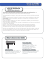
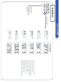
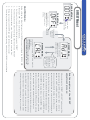
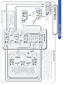
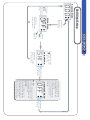
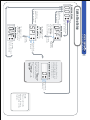
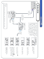
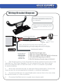
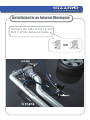
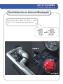
gizzmo
ELECTRONICS
Wiring/Bracket Diagram
Disconnect the negative terminal of
the battery BEFORE proceeding with
the installation.
Please ensure you follow the image
on the left re the assembly of your
bracket
Solenoid
2 Core Solenoid Cable
3 Core Cable
YELLOW:
RED:
RPM Input
12V Power Supply
BLACK: Earth
Notes: The RPM input wire MUST GO TO A DIGITAL LOW
VOLTAGE SOURCE e.g. ECU tach output, ECU to Igniter wire etc.
This wire MUST NOT go to a high voltage source e.g. coil negative
IBCR
1
2
3
4
PRESSURE SUPPLY
5
Loom side of
IBCR2 Plug
looking INTO
plug from
IBCR2 side
1: BLACK Ground supply input
2: RED 12V+ Power Supply input
3: RED 12V+ Supply output from IBCR2 to Solenoid
4: YELLOW RPM signal input to IBCR2
5: BLACK Switching Ground output to Solenoid
1.
The Pressure port is to be connected to a direct pressure source at an inlet
manifold e.g. Fuel Press Regulator. Do not connect this to any other device
such as a solenoid valve or blow off valve. A 3mm Y connector is provided
to assist plumbing.
2.
Mount the solenoid with the un-used port facing downwards. Connect the
hoses as per the correct application (actuator or external wastegate).
3.
Connect the Red wire to a good fused power source that is live only when
the ignition switch is in the on position.
4.
Connected the Black wire to a good clean chassis earth.