1
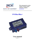
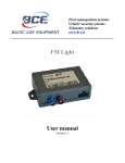
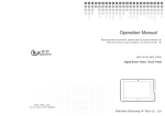
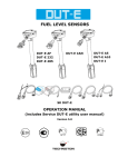
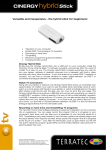
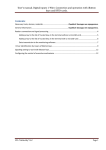
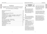
GPS / GLONASS tracker FM Blue+ User manual Version 1.2 Fleet management systems Vehicle security systems Telemetry solutions www.bce.lt Contents 1. FM Blue+ general device information ............................................................................................ 3 1.1. Safety and legal information ........................................................................................................ 3 1.2. Description ................................................................................................................................... 3 1.3. Package......................................................................................................................................... 4 1.4. Technical specifications ............................................................................................................... 4 1.5. Physical properties ....................................................................................................................... 5 1.6. Pinout & diagnostic LEDs............................................................................................................ 7 1.6.1. Pinout .................................................................................................................................... 7 1.6.2. Diagnostic LEDs ................................................................................................................... 8 1.7. Installation .................................................................................................................................... 9 1.8. Configuration ............................................................................................................................. 10 1.9. Support ....................................................................................................................................... 10 1.10. Document versions ................................................................................................................. 10 2. Annex 1. Installation instructions .................................................................................................. 11 3. Annex 2. Configuration manual .................................................................................................... 16 3.1. BCE Device Configuration Manager ......................................................................................... 16 3.1.1. Users and Dealers ............................................................................................................... 16 3.1.2. Devices and Retranslators ................................................................................................... 18 3.1.3. Firmware ............................................................................................................................. 22 3.1.4. XML settings ...................................................................................................................... 22 3.1.5. GSM operator groups .......................................................................................................... 24 3.1.6. Device logic ........................................................................................................................ 25 3.1.7. Function signals .................................................................................................................. 27 3.1.8. Functions ............................................................................................................................. 28 3.1.9. Configuration examples ...................................................................................................... 30 3.1.10. Dataset7_Mask1 description table .................................................................................. 33 3.1.11. Dataset7_Mask2 description table. FMS-CAN (J1939) ................................................. 34 3.1.12. Dataset7_Mask3 description table .................................................................................. 36 4. Annex 3. Connecting additional sensors. Wiring diagrams ........................................................ 37 4.1. Volvo CAN-bus (using CAN H, CAN L and RS485) ................................................................... 37 4.2. Renault CAN-bus (using CAN H, CAN L and RS485) ................................................................ 38 4.3. LLS fuel sensor (one sensor, frequency mode) ............................................................................. 39 4.4. LLS fuel sensor (two sensors, frequency mode) ............................................................................ 40 4.5. LLS fuel sensor (one sensor, analog mode) ................................................................................... 41 4.6. LLS fuel sensor (two sensors, analog mode) ................................................................................. 42 4.7. LLS fuel sensor (EIA 485/ RS485)................................................................................................ 43 4.8. FM Blue – ADP CAN interconnection .......................................................................................... 45 4.9. iButton............................................................................................................................................ 47 4.10. 1-WIRE temperature sensor ......................................................................................................... 48 Fleet management systems Vehicle security systems Telemetry solutions www.bce.lt 1. FM Blue+ general device information 1.1. Safety and legal information Do not disassemble the device. May interfere operation of adjacent electronic devices. Device may be damaged by water and high humidity. Installed by qualified professionals only. Copyright © Baltic Car Equipment, Ltd. All rights reserved. Reproduction, transfer, distribution or storage of part or all of the contents in this document in any form without prior written permission of Baltic Car Equipment is strictly prohibited. 1.2. Description FM Blue+ is a device with GPS/Glonass and GSM connectivity, designed for object tracking. It is able to acquire information on object location, speed, direction, etc. and transfer the data via GSM network. Digital and analog inputs of the device may be used to connect different external sensors/devices. Outputs of the device may be used to control external equipment remotely. FM Blue+ can read CANbus data from vehicles without additional adapters and has various CAN protocols integrated: FMS CAN (protocol J1939) Volvo/Renault (protocol J1708, without adapters) OBDII (diagnostic protocol for light vehicles, SAE-1979) CAN protocols for light vehicles Flexible configuration allows users/dealers to adjust the device to meet their specific requirements. All device settings and firmwares are updated remotely via GPRS. It is possible to create setting templates for groups of vehicles, use mass updates and create unique device operation logic, fulfilling requirements of most cases on the market. Fleet management systems Vehicle security systems Telemetry solutions www.bce.lt 1.3. Package FM Blue+ is shipped to a customer in a cardboard box and contains all required components for operation*. Package contents: 1. FM Blue+ device (control unit) 2. External GPS antenna 3. External GSM antenna 4. Wires + 1A fuse Note. SIM card is not included, but is necessary to operate the device. Contact your local GSM operator to purchase a SIM card. BCE recommends an M2M SIM card for best performance and reliability. 1.4. Technical specifications Table 1. FM Blue+ technical specifications Interfaces 4 digital inputs 3 x ADC: 1 x ADC: 0..16 V, 11 bit 2 x ADC: 0..36 V, 11 bit 2 digital outputs CAN data interfaces: FMS CAN (J1939) Volvo/Renault (protocol J1708, without adapters) OBDII (diagnostic protocol for light vehicles, SAE-1979) CAN protocols for light vehicles 1-WIRE RS-232/RS485 GSM Telit GE865 Quad GSM/GPRS protocol stack 3 GPP Release 4 compliant Sensitivity: <-107 dBm @ 850 / 900 MHz <-106 dBm @ 1800 / 1900 MHz GPRS class 10 (up to 85.6 kbps), class B Jamming detection Internal memory 4 Mb, up to 150.000 entries Accelerometer: LIS33DE GPS / GLONASS U-blox / Telit A-GPS support Precision: Position: 2.5m CEP Take off time: 1 second „hot start“ in the open air < 30 seconds warm start in the open air (average) 30 seconds cold start in the open air (average) Sensitivity: -148dBm cold start -162dBm tracking Physical properties Dimensions (HxWxD): 26 x 80 x 55 mm Weight: approximately. 73 g Operating temperature range Operation / Storage: -40 Cº to +85 Cº Electrical properties Operation’s flow: Active Mode: at 12V - < 50mA Sleep Mode: at 12V - < 8mA 6 – 34V operating voltage, min 10V to start Protection from impulses up to 120V Power cut-off registration to the event log Fleet management systems Vehicle security systems Telemetry solutions www.bce.lt 1.5. Physical properties 7 9 1 1 TOP SIDE 5 8 3 6 4 2 2 Fig. 1. FM Blue+ front view. Note. To insert a SIM card, loosen device mounting screws at the bottom of the device. Table 1. FM Blue+ components No. 1 2 3 4 5 6 7 8 9 Short description Mounting screws place Device box mounting screws Device and GPS status LED GSM status LED GPS antenna socket (blue) GSM antenna socket (purple) IMEI and hardware ID sticker SIM card Socket 2x8 pins Fleet management systems Vehicle security systems Telemetry solutions www.bce.lt 3 3,5 80 19 7 55 10 7,5 5 101 6 26 Fig. 2. FM Blue+ dimensions Fleet management systems Vehicle security systems Telemetry solutions www.bce.lt 1.6. Pinout & diagnostic LEDs 1.6.1. Pinout EIA485 (A) Green RS23 (TX) Purple CAN LOW Orange 1-Wire Yellow IN2/ADC4 Green/ black IN3/OUT1 Purple/black IN4 Blue/black IN5 Grey/black EIA485 (B) Green/black RS232 (RX) Blue CAN HIGH Orange/black ADC5 Grey ADC3/OUT2 White EXT BAT/ADC6 Brown BATTERY + Red GROUND Black Fig. 3. FM Blue+ pinout and cable colors. Electrical properties of the device are shown in Table 2. Table 2. FM Blue+ electrical properties. ADC Power supply multiplier (adc2) 0.025V +-1.5% ADC 11bit ADC 3 multiplier (adc3) 0.01V +-1.5% ADC 11bit max 20V ADC4 multiplier (adc4) 0.0205V +-1.5% ADC 11bit max 40V ADC5 multiplier (adc5) 0.0205V +-1.5% ADC 11bit max 40V Fleet management systems Vehicle security systems Telemetry solutions www.bce.lt ADC EXTBAT multiplier (adc6) 0.0205V +-1.5% ADC 11bit max 40V EXT BAT OUT (+) 13.5V regulated 1.5A limited OUT1 (-) 1.7A OUT2 (-) 1.7A Power supply, min start up voltage 10V Power supply, min operating voltage after start up 6V Power supply, stage1 30V Clamping voltage clamping type 34V varistor IN2,IN3,IN4,IN5 Max measuring frequency, accuracy 3Khz, +/-1Hz IN2, IN3, IN4, IN5 voltage threshold 4.7V, +/-3% 1.6.2. Diagnostic LEDs FM Blue+ has two indication LEDs – for GPS and GSM modem status. LEDs start flashing only if IN5 digital input is connected to battery +. Fig 4. LED flash signal. Example. Fleet management systems Vehicle security systems Telemetry solutions www.bce.lt Table 3. Short flash meaning. GPS status. Short flashes count Meaning 1 No GPS signal 2 Poor precision. HDOP>1.5 3 3 satellites locked. HDOP<1.5 … ... 12 12 satellites locked. HDOP<1.5 Table 4. Long flash meaning. GSM modem status. Long flashes count Meaning 1 Modem connected to server, Modem connected to Internet, Modem GPRS registered, Modem GSM registered, Modem SIM card ok, Modem turned on 2 Modem connected to Internet, Modem GPRS registered, Modem GSM registered, Modem SIM card ok, Modem turned on 3 Modem GPRS registered, Modem GSM registered, Modem SIM card ok, Modem turned on 4 Modem GSM registered, Modem SIM card ok, Modem turned on 5 Modem SIM card ok, Modem turned on 6 Modem turned on 7 Device started 1.7. Installation FM Blue+ is installed where risk of mechanical damage, high humidity and extreme heat is low. Device is mounted stable to vehicle body, therefore ensuring correct operation of the internal accelerometer. Complete installation manual is available as Annex 1. Fleet management systems Vehicle security systems Telemetry solutions www.bce.lt 1.8. Configuration FM Blue+ is meant to be operated through a configuration/retranslation server, where dealers/users can configure their devices to fulfill specific requirements. Configuration manual is available as Annex 2. 1.9. Support FM Blue+ is built to be a reliable, stable and easy to install device. Please read and follow provided installation and operating instructions carefully. However, if you encounter difficulties while installing or using this product, technical support is available and may be reached by e-mail [email protected]. 1.10. Document versions Table 5. Document versions Version Date 1.0 2012.03.20 1.1 2012.11.09 1.2 2013.06.05 Changes Document created. Updated configuration description, added LLS connection Updated configuration description, various sensor connection wiring diagrams added. Fleet management systems Vehicle security systems Telemetry solutions www.bce.lt 2. Annex 1. Installation instructions List of suitable vehicles FM Blue+ is intended for all vehicles with petrol or diesel engines, where negative pole is body of the vehicle. Device must be connected to the vehicle battery, ensuring constant power supply even if the engine is not working and ignition is off. When active, FM Blue+ uses a small amount of direct current (DC) – less than 50 mA at 12V. It can be mounted in 12 V or 24 V vehicles. Standby mode This is a mode of the device when the vehicle ignition is turned off, and there are no active alarms. In this mode, the GPS receiver is switched off in the control unit (in order to reduce power consumption) and communication with the server intervals are increased. Device switches to active mode if programmed trigger is detected (for example accelerometer signal). Active mode This is a mode when ignition is on, or when any programmed trigger is active. In this mode, GPS receiver is enabled in the central unit and connection with the server is carried out more frequently. After ignition is switched off, the central unit remains active for another 10 minutes. Free configuration of data dispatch frequency is possible. During the data transfer (GSM / GPRS communications), short-term increase in current consumption of up to 100 mA is possible. Power-line (primary or back up battery) has to be connected via 1A fuses. Basic instructions before beginning the installation Quality of connections, location of the device and its’ antennas, etc. play a significant role on accurate operation of the system. Below are some tips and rules for correct installation to attain professional quality and ensure maximum efficiency of the device. Location for central unit installation Central unit should be hidden in a difficult to access location to prevent unwanted interference by unauthorized persons. Small size and flat body makes it easy to do and allows use of small gaps for installation. Fleet management systems Vehicle security systems Telemetry solutions www.bce.lt The device must be fixed in the vehicle in position where connectors are oriented to the ground. This will prevent moisture condensation inside the unit. Electrical connections Control unit must be powered by continuous voltage. When starting the engine, voltage can not fall below 8 V. It is desirable that power supply for the device is connected to the factory cable led from battery terminals. This allows operation of the unit despite of failure of any vehicle fuses. Mechanical connections To highest possible extent, cavities in the vehicle should be used for wiring. If you need to make a new hole, it must be protected against corrosion appropriately! Wiring connection must be made by brazing, and not merely mechanical wire connection. It is especially important to protect the connections with insulation for high-resistance atmospheric conditions. Do not use insulation with unknown resistance parameters. Efforts should be made to tie the new wiring into the car's standard wiring bales. Installation of central unit Steps to install central unit: Insert a SIM card into the device; Install GSM and GPS antennas; Install central unit; Connect power supply; Connect array; Connect ignition wire to a digital input (usually IN5); Connect other devices (optional). SIM card SIM card must be inserted into the device before starting installation. The device must be turned off when inserting SIM card. Before inserting the SIM card, make sure you have activated GPRS connection, the card’s PIN code must be disabled. If the vehicle is travelling to foreign countries, roaming service must be activated for the SIM card. The SIM card and phone number must be checked and clearly marked on the installation certificate of the device. Fleet management systems Vehicle security systems Telemetry solutions www.bce.lt IMPORTANT! Before inserting a SIM card, do not forget to disable PIN code. Otherwise, the device will not work, and the SIM card will be blocked. GPS antenna installation GPS antenna is the main element responsible for vehicle positioning accuracy and quality. To ensure best possible GPS signal reception and evaluating GPS signal character, there are strict requirements for correct installation of GPS antenna: The accordingly marked side of the antenna must be invariably directed to the sky (sticky side facing ground). The antenna must be oriented horizontally (not at an angle) and oriented with the corresponding side towards the top. The antenna should not be covered with metal sheet or reinforced glass. In vehicles with standard glass (e.g., without built-in heating elements), antennas can be mounted on panels or under its lining at the windscreen. The antenna must have open view to the sky, unimpeded with windowsills or other metallic elements. In vehicles where it is not possible to place the antenna under the windscreen (vertical windscreen, armored glass), the antenna can be installed in the vehicle’s bumper or in other element that ensures the free access to the sky. The installed antenna should be hidden and not visible. Fixing of the antenna must be stable and immobile, providing for the installation durability. It is necessary to take into account events, which may lead to loss of antenna’s stability, to select the mounting location and methods that would allow to avoid these factors. Antenna’s position changes are not permitted, because it may result in loss of appropriate antenna’s orientation. Cable to the GPS antenna must be as short as possible, and avoid areas with high electromagnetic interferences. Arbitrary lengthening or shortening of the cable is not allowed. The wire surplus should be twisted into a circle with a radius larger than 10 cm. The cable must not be bent, or twisted at tight angles. GPS antenna cable must not be laid in parallel to GSM antenna cable, also the two cables cannot be twisted together. GSM antenna installation GSM antenna is responsible for transfer of collected data and connection with central server. Good antenna’s performance is the key element in obtaining information from the device. Fleet management systems Vehicle security systems Telemetry solutions www.bce.lt GSM antenna does not require orientation to open sky; however you should be aware that metal elements weaken the GSM signal. GSM antenna must be installed in more than 40 cm away from the control unit, as well as from other electronic devices. It is also necessary to take into account the emission of the antenna’s high frequency radio waves, which may interfere with operation of electronic devices. In case antenna is difficult to place in the cabin (strong GSM signal suppression), it may be installed in any other element allowing the reception of the GSM signal. As for GPS antenna, GSM antenna should be hidden from outside observers. Device installation Central unit is only mounted in inside of the vehicle, it can not be installed in the engine chamber, next to the cabin, or in the area of exposure to direct external conditions. Central unit must be hidden (for example, under the upholstery), as well as protected from moisture exposure. Device must be fastened in a stable position to avoid random twitches and displacements (suspension on cables is strictly prohibited). Central unit must be mounted horizontally. Precise orientation is of particular importance to flawless operation of the system, since the device is equipped with acceleration sensors recording the data which directly affects the results obtained. Pinout and cable colors are shown in figure 1. EIA485 (A) Green RS23 (TX) Purple CAN LOW Orange 1-Wire Yellow IN2/ADC4 Green/ black IN3/OUT1 Purple/black IN4 Blue/black IN5 Grey/black EIA485 (B) Green/black RS232 (RX) Blue CAN HIGH Orange/black ADC5 Grey ADC3/OUT2 White EXT BAT/ADC6 Brown BATTERY + Red GROUND Black Annex 1. Fig. 1. FM Blue+ pinout. Fleet management systems Vehicle security systems Telemetry solutions www.bce.lt Power supply Power supply of central unit has to be connected directly from the vehicle’s battery, using 1A fuse. IMPORTANT! Power supply may be connected to the central unit only after connecting GSM and GPS antennas! When disconnecting the device, you must first turn off the power supply, and only then disconnect the antennas! Ground wire Ground wire should be connected to the vehicle body. A reliable electrical contact with the body must be ensured, wire has to be bolted. Ignition input (combustion lock status) Connect a wire of the vehicle where voltage is present only when ignition is activated to IN5. Universal digital inputs (optional) Universal Digital inputs (IN2; IN3; IN4; IN5) are intended to collect data from remote devices. Analog inputs (optional) Analog inputs are intended to collect data from remote devices by measuring voltage. ADC3 range 020V; ADC4, ADC5, ADC6 range 0-40V. Fleet management systems Vehicle security systems Telemetry solutions www.bce.lt 3. Annex 2. Configuration manual 3.1. BCE Device Configuration Manager BCE Configuration Manager is a web based service for adding new devices, changing device settings, firmware, operators, creating retranslations and more. This service allows you to configure and manage your devices remotely. You may access it at http://fmset.eu if you have an account. Once you log in to the website, home screen will appear. In this page you can find useful information about Baltic Car Equipment products: User manuals Hardware revision code description and pinout Event meaning list Status LED flash meaning Master SIM card BCE configuration manager includes the following tabs: 1. 2. 3. 4. 5. 6. 7. 8. 9. Home Users Dealers Devices Firmwares GSM operator groups XML settings Device logs Audit info (for administrators only) 3.1.1. Users and Dealers Each dealer has a user account and can control all his devices via BCE Device Configuration Manager. You may create new user accounts. The fields which are marked red must be filled (user ID, password, role), other fields are optional (see Picture 2). A dealer must be assigned to every user. It should be created in dealers tab first. Fleet management systems Vehicle security systems Telemetry solutions www.bce.lt Picture1. User creation window Dealer is necessary for proper device management in the configuration system. Your dealer and user will be created by Baltic Car Equipment team, when you start using configuration manager. If the dealer has a network of dealers, he can control the sub-dealers and their devices. While creating a dealer, your dealers name will be filled automatically in “parent dealer” field. Quantity of sub dealers is not limited. Picture2. Dealer creation window Fleet management systems Vehicle security systems Telemetry solutions www.bce.lt After creating the devices you can change the dealer for one or a group of them. In the “Devices” tab select the devices you want to change the dealer for, click “Transfer selected devices”, select the dealer you need and click “Transfer”. 3.1.2. Devices and Retranslators In the ”Devices” tab you can change mane device parameters and see its status. First step is creating new device. Select hardware version (M version) and press next. Device settings window will appear (Picture3). Fill in the required fields: 1. IMEI number. It is printed on the device 2. Operator group. It is optional. Will be explained with details in chapter 6. 3. Preferred firmware. Will be explained with details in chapter 6 4. XML settings. Will be explained with details in chapter 6 5. Notes. Optional, usually hardware version filled. 6. Phone number. Telephone number of the SIM card inserted in the device. 7. Server settings 7.1. Host. Filled in automatically. Server IP or domain name. 7.2. Port. Filled in automatically 7.3. APN name. Must be provided by your operator 7.4. APN user. Must be provided by your operator. Often left “blank”. 7.5. APN password. Must be provided by your operator. Often left “blank”. 7.6. Service1 number. Telephone number to which device could send a message with its status. 7.7. Service2 number. Telephone number to which device could send a message with its status. 8. 1st custom value. Additional settings field. 9. 2nd custom value. Additional settings field. Picture 3. New device Fleet management systems Vehicle security systems Telemetry solutions www.bce.lt Picture 4. Device settings If you are creating many devices with same parameters, you can save one device as a template (put a tick in a checkbox “Template”, picture4). Choose it from the “Template devices” (Picture3), it will be in a drop box list sorted by IMEI. Once device is created you can easily find it by entering one or few search parameters. There are few more useful functions in devices tab. When you generate a list of devices, on the left side of the IMEI you will see two symbols and a checkbox (Picture5.) Picture5. The checkbox is used for device transfer to another dealer (sub-dealer), or mass device update. This means you can update many devices at once and update more than one parameter at a time. Fleet management systems Vehicle security systems Telemetry solutions www.bce.lt The upper symbol is used to monitor device status (Picture6.) Picture6. device state As we can see, main parameters are represented in this picture: IMEI; position time; coordinates; satellites count; HDOP; Input time and status (active/inactive); XML settings state; firmware state; last activity. This function is very convenient when you want to check device state fast and help with device surveillance. The lower button (Picture5.) will open device logs in new window (Picture7.). Fleet management systems Vehicle security systems Telemetry solutions www.bce.lt Picture7. Device logs IMEI is picked automatically, you just need to choose period for which you want to see device logs and hit search button. Logs are represented in a code and has an explanation. These logs let our team to identify and solve various problems, which are related to our device or operator service. Note. Only most important events are described in the logs. Retranslators For proper data sending to tracking platform, retranslator must be created (Picture8). Retranslator type should be set and server address and port entered, f.e.: Retranslator type – Wialon IPS Server address – 193.193.165.165:20482 Picture 8. Retranslators Fleet management systems Vehicle security systems Telemetry solutions www.bce.lt At the moment retranslator supports following protocols: FM Codec 8 GPS Gate BCE generic Wialon IPS 3.1.3. Firmware Firmware is the combination of persistent memory and program code and data stored in it. It provides the control program for the device. Firmwares are created and uploaded by BCE team. They are sorted by device version. KB – 4th hardware version LB – 4.5 hardware version MB – 5th hardware version You can see in the notes what updates were made in specific firmware. Picture 9. Firmware list example 3.1.4. XML settings XML settings may be uploaded to the device and used to tune it for the best performance and requirements of your system. You will find several prepared settings created by Baltic Car Equipment team. However, you may create settings that meet your specific needs. After the settings are ready just upload them to the devices. XML settings template must be created and assigned to a device. It helps you control your devices: Enable/disable preferred parameters Set data fix and data send periods Control physical and virtual inputs/outputs Set internal functions (TIMER1, TIMER2) Configure EIA485, RS232, 1-WIRE communication bus Fleet management systems Vehicle security systems Telemetry solutions www.bce.lt XML settings template includes many functions and signal conditions, which makes device widely adaptable and allows you to obtain high functionality. Main steps of settings creation are represented in Picture 10. Picture 10. XML set up scheme New XML settings Picture 11. New XML settings main window In the first window you must set up primary parameters: a) Name; b) Device version (optional); c) Notes (optional); d) Dealer Fleet management systems Vehicle security systems Telemetry solutions www.bce.lt 3.1.5. GSM operator groups GSM operator group is used for more accurate device connection to operators. By setting up a group, you point device to connect to preferred operator from the list. There are two possibilities: 1. Create and assign operator group to device. When starting new operator search device will first try to connect to operator from the list, but if preferred operator is not available, device will connect to any other operator visible in that area. 2. Create and assign operator group to device, as well as set up function “2.1 F_InternetConnection” with value “Permit” only when preferred operator active. This way device won’t connect to internet if connected to a non preferred operator. As you can see in picture9, you need to fill in groups name, set up a dealer, fill in some notes if needed and enter preferred operators codes. Code consists of five digits, first three digits stands for mcc (mobile country code), it depends on the country. Last two digits stands for mnc (mobile network code), it defines specific operator. Picture 12. Operators group example Fleet management systems Vehicle security systems Telemetry solutions www.bce.lt 3.1.6. Device logic When pressed “logic”, functions list will appear. By pressing “plus” symbol in the left side of the functions name, you will add parameters to every function. Parameters quantity is unlimited. As you can see in Picture 13, parameters are represented in a code. This code refers to parameters value and its signal condition. Picture 13. Logic template example When you add a parameter, second step is to set its value and pick signal conditions (if needed). There are three possible conditions: a) Present b) Not present c) Don’t care In the example below (Picture 14) you can see internet connection configuration. Value is set to “permit” if specific conditions are met (device is not in roaming network; IN1 – motion is detected; IN5 is detected). Fleet management systems Vehicle security systems Telemetry solutions www.bce.lt Picture 14. Functions parameter There are three possible value formats: a) drop box; b) check box; c) numeric value; d) Time interval (made specifically for “TIMER1” function). All signal conditions and all functions are described in Table1 and Table2. Once settings are created, you can easily find them using search tool. Two search filters are available: a) Name; b) Dealer; In order to avoid the creation of settings from the beginning copy function was added. Open already created settings - “Duplicate” button will appear. This way you will be able to create many setting templates in a short time. Fleet management systems Vehicle security systems Telemetry solutions www.bce.lt 3.1.7. Function signals Signal name Signal description Reset Modem on IN1 – motion IN6 Reserved Turn on temporarily after the system is restarted to indicate the event Modem of the device is enabled Virtual input, used for motion detection Virtual programmable input Reserved for future System time registered The device has turned UTC time internally from GPS or internet Reserved Reserved for future GPS signal does not meet the minimum requirements according to “F_GpsQualityMaxHdop” and “F_GpsQualityMinSat” GSM/DCS jammer is detected and it is disturbing normal use of GSM/DCS service Device is registered to a roaming network Device is registered to any network Device is registered to GPRS data services Device is connected to internet Device is registered to an operator from the preferred list GPS speed detection over 10km/h SIM card is inserted and PIN code removed Physical – digital input Physical – digital input Physical – digital input Physical – digital input Virtual input, battery charging detected Virtual programmable input Every hour for 10 minutes period Every six hours for 10 minutes period There is more data in stack than allowed Voice call detected, settings locked for 30 minutes Data call detected, settings locked for 30 minutes General first static signal General second static signal Special structure for internal timer signal “Dallas key” detected Special structure for internal timer signal Poor GPS signal GSM jamming Roaming GSM registered GPRS registered Internet active Preferred operator active GPS speed present SIM card ok IN2 IN3 IN4 IN5 IN7 – engine on IN8 One hour tick Six hour tick Stack size threshold reached Voice call Data call Static signal1 Static signal2 Timer1 IbuttonPresent Reserved Table1. Signal descriptions Fleet management systems Vehicle security systems Telemetry solutions www.bce.lt 3.1.8. Functions Functions name 1.1 F_ModemPower 1.2 F_GpsPower 2.1 F_InternetConnection 2.2 F_ServerConnection 2.3 F_DataSendPeriod 2.4 F_DataSendOnInputsChange 2.5 F_BroadcastMessagesPeriod 3.1 F_GpsQualityMaxHdop 3.2 F_GpsQualityMinSat 3.3 F_GpsReadPeriod 3.4 F_MaxTimeBetweenTwoGpsPoints 3.5 F_GpsCourseChangeFix 3.6 F_GpsSpeedChangeFix 3.7 F_InputsChangeFix 4.1 F_Dataset7_Mask1 4.2 F_Dataset7_Mask2 4.3 F_Dataset7_Mask3 5.1 F_GeneralBitConfig 5.2 F_VibrationThreshold 5.3 F_NotDeliveredDataThreshold 5.4 F_In8VoltageThreshold Description/value expression GSM modem power mode (on/off) GPS device power mode (on/sleep) Create new internet connection (PDP context*), [permit/ban] Controls connection to server (connect/disconnect after 10 minutes) Period in which data is sent to server (automatic/custom) Mask of inputs which may generate data transmission without waiting period timeout (tick a check-box to select desired input) Reserved. Will be able in near future Maximum HDOP* of position to accept it to read (Recommended value – 35) Minimum satellites count for acceptance to read it Period in which coordinates are read from GPS and put to internal track filter (never/value=seconds) Maximum time between two fixed points (never/value=seconds) Minimum course change for device to fixate it (value expressed in degrees) Fixation of vehicles speed difference from the last set value (expressed in km/h) Registers change of selected input state (tick a check-box to select desired input) Selected data will be included into the data packet (see annex 1) Selected FMS-CAN (J1939)* data will be included into the data packet (see annex 2) Selected data will be included into the data packet (see annex 3) General bit configuration (tick a check-box to select desired function) Vibration (IN1) threshold (if value > selected threshold, IN1-motion=1). Used for detecting motion, recommended value - 200 Stack size threshold to generate signal “Stack size threshold reached”. Value expressed in bytes. Power supply voltage threshold. Expressed in volts (if value > threshold, IN8=1) Fleet management systems Vehicle security systems Telemetry solutions www.bce.lt 5.5 F_In6VoltageThreshold 5.6 F_FrequencyCounterSelect 5.7 F_CanFunctionSelect 5.8 F_EIA485FunctionSelect 5.9 F_RS232FunctionSelect 5.a F_NewConectionsToInternetLimiter 5.b F_Timer1 5.c F_Timer1_GMT 5.d F_Timer2_Control 5.e F_Timer2_Threshold 5.f F_OUT1_Control 5.g F_OUT2_Control 6.1 F_Dataset1_Timeout 6.2 F_Dataset2_Timeout 6.3 F_Dataset3_Timeout 6.4 F_Dataset4_Timeout 6.5 F_Dataset51_Timeout 6.6 F_Dataset8_Timeout 6.7 F_Sms_TrigerMaskRising 6.8 F_Sms_TrigerMask_Faling 6.9 F_Sms_NextSmsTimeout 6.a F_Sms_MaxSmsPerHour Reserved_43…..Reserved_63 ADC3 voltage threshold. Expressed in volts (if value > threshold, IN6=1) Input mask for counter – frequency mode (tick a check-box to select desired input mode). Used for sensors, to work in counter or frequency mode Selects CAN function. Enables CAN bus reading. Possible values: J1939-FMS; J1939 OBDII*; FMS ACK; FMS request; RS485* function select. Enables RS485 input reading. Used for LLS*sensors and J1708* Reserved. Will be able in near future. Limits next possible connection to internet (value expressed in seconds) Special structure for internal timer signal Used to set GMT value. Special structure for internal timer signal Time threshold expressed in seconds. Used with 5.d function Function for OUT1 output control. Works in three modes: off1 – output disabled, but can be controlled with GPRS commands; on (minus) – enabled; off2 – disabled; Function for OUT2 output control. Works in three modes: off1 – output disabled, but can be controlled with GPRS commands; on (minus) – enabled; off2 – disabled; Not used for wialon Not used for wialon Not used for wialon Not used for wialon Not used for wialon Not used for wialon Sms mask value. Sending sms when changing from 0 to 1 (tick a check-box to select desired input) Sms mask value. Sending sms when changing from 1 to 0 (tick a check-box to select desired input) Next sms timeout. Expressed in seconds Maximum sms per hour Reserved for future Table2. Function descriptions Fleet management systems Vehicle security systems Telemetry solutions www.bce.lt HDOP – horizontal dilution of precision. This gives an indication of precision of the position fix from GPS, based on the satellites it is currently using and its geometry. PDP context – packet data protocol context is a term used in the mobile wireless network indicating a logical association between an MS (mobile station) and PDN (Public data network) running across a GPRS network. The context defines aspects such as routing, qos (quality of service), security, billing etc. FMS-CAN (J1939) – “fleet management systems” interface is a standard interface to vehicle data of commercial vehicles. J1939 is a vehicle bus standard used for communication and diagnostics among vehicle components. OBD-II – on board diagnostics, is an automotive term, referring to a vehicles selfdiagnostic and reporting capability. The OBD-II standard specifies the type of diagnostic connector and its pinout, the electrical signaling protocols available, and the messaging format. EIA-485, also known as TIA/EIA-485 or RS-485, is a standard defining the electrical characteristics of drivers and receivers for use in balanced digital multipoint systems. J1708 - standard used for serial communications between ECU (Electronic control unit) on a heavy duty vehicle and also between a computer and a vehicle. LLS – Liquid level sensor 3.1.9. Configuration examples 5.1 F_GeneralBitConfig includes two functions: a) Battery charge b) Odometer By ticking odometer checkbox, you enable/disable internal odometer, which is represented in device messages and can be used as mileage counter. Internal odometer was calibrated by our engineers on a referenced road and had a deflection of 0.2%. Battery charge function is needed when external battery is used. When function is enabled, PLUS [+] signal is generated on the “EXT BAT” output. It is advisable to assign IN5 (ignition) condition to this function, that external battery would be charged only when vehicles engine is working. Fleet management systems Vehicle security systems Telemetry solutions www.bce.lt 5.3 F_NotDeliveredDataThreshold. Generates signal – stack size threshold reached. You can use this signal in any other function. Just set the limit of bytes and change condition of your preferred function (1. Not present; 2. Present). Example: Set the limit of threshold (10000 bytes). Select function 1.1 F_InternetConnection. Change signal (stack size threshold reached) condition to – “present” (picture4). Result: device connects to internet only when data limit in internal memory is reached. 5.7 F_CanFunctionSelect. Used for vehicles with CAN bus interface. Select the value from the list depending on protocol which is used in your vehicle. Example: J1939 FMS – message protocol for bus, truck and trailer market. Working without requests. J1939 FMS Request – reading J1939 messages only with requests. J1979 OBD II (On board diagnostics) – standard, that specifies the type of diagnostic connector and its pinout, the electrical signaling protocols available and the messaging format. Uses J1979 protocol. J1939 FMS ACK – similar to other J1939 protocols, just makes confirmations for successfully transmitted data. 5.8 F_EIA485FunctionSelect. This function lets you control RS485 interface. It can be used for LLS sensor connection (up to 4 sensors), and Volvo/Renault CAN bus reading. If you use LLS sensors, select value – “LLS sensor reading” ( 4.3 F_DataSet7_Mask3 functions parameters – “LLS group1” and “LLS group2” must be enabled). “J1708 No FMS gateway” is used for vehicles without gateway, reading with requests. “J1708 FMS gateway reads CAN bus without requests. 5.b F_Timer1 function generates signal “Timer1”, which you can use in any other function as its condition. As you can see in the function window, you can pick “work days” – days, when signal will be active, “Signal on time” – at this specific time signal is activated, “Signal off time” – at this specific time signal is deactivated. 31 Fleet management systems Vehicle security systems Telemetry solutions www.bce.lt This function could be convenient for clients, whose vehicles work at specific days and hours. Just set the time and change signal condition in preferred functions (f.e. 2.1 F_InternetConnection or 2.2 F_ServerConnection). Function 5.c F_Timer1_GMT is used jointly for setting your time zone. 5.d F_Timer2_Control and 5.e F_Timer2_Threshold forms another set of programmable timer. Timer2 signal is generated and can be chosen from conditions list. Timer2_Control has the following values: a) Pause b) Time increment c) Time decrement d) Reset to 0 e) Value at 60 sec. f) Value at 60 min. Time increment – time increases every one second. Time decrement – time decreases every one second. Reset to 0 – timer is reset to 0. Value at 60 sec. – timer set for 60 seconds. Value at 60 min. – timer set for 60 minutes. Timer2_Threshold – is a limit expressed in seconds. Just set desirable threshold, pick a value in Timer2_Control and Timer2 signal is ready to use. Example. Threshold is set to 40 seconds, value set at 60 seconds (when ibutton present), time decrement (when ibutton not present). It means that when device reads ibutton, timer is set for 60 seconds, user pulls back ibutton – time starts to decrement until reaches 40 seconds limit, then signal is deactivated. Signal is active for 20 seconds, you can use this time to control other preferred function (f.e. OUT1). In this example three functions was combined. Often it will be used for complex operations. 32 Fleet management systems Vehicle security systems Telemetry solutions www.bce.lt 3.1.10. Dataset7_Mask1 description table Parameter Coordinates Digital inputs ADC1 ADC2 ADC3 ADC4 ADC5 ADC6 ADC7 ADC8 c1,c2 c3,c4 LVL1 LVL2 GSM info Description This parameter includes: Longitude HDOP Latitude Course Speed Altitude Satellites Odometer IN1 – IN16. Control of physical and virtual digital inputs. Board voltage. Shown as adc12 in wialon Analog input. Physically shares same pin with OUT2. Analog input. Physically shares same pin with IN2 Analog input Analog input. Physically shares same pin with external battery connection. Analog input Analog input Counter/Frequency parameters group. Represents IN2, IN3 inputs. Counter/Frequency parameters group. Represents IN4, IN5 inputs. Used for analog sensors connection. Represents ADC3 input. Shows approximated value. Used for analog sensors connection. Represents ADC4 input. Shows approximated value. This parameter includes: mcc (mobile country code) mnc (mobile network code) lac (local area code) cell_id (ID of station to which device is connected at the moment) gsm_lvl (strength of GSM signal [dBm]) ta (distance to nearest station) Table3. Dataset 33 Fleet management systems Vehicle security systems Telemetry solutions www.bce.lt 3.1.11. Dataset7_Mask2 description table. FMS-CAN (J1939) Parameter Wheel speed Acceleration pedal Total fuel Fuel level sensor Tachometer Engine hours Mileage Engine temp. Fuel level[2] Engine load Service distance TCO1* Air temp. Driver ID Fuel rate Description Speed of the vehicle as calculated from wheel or tail-shaft speed. The ratio of actual position of the analogue engine speed/torque request input device to the maximum position of the input device. Accumulated amount of fuel used during vehicle operation. Ratio of volume of fuel to the total volume of fuel storage container. Engine speed Accumulated time of operation of engine. Distance travelled. Temperature of liquid found in engine cooling system. When Fuel Level 2 is used, Fuel Level 1 represents the fuel level in the primary or left-side fuel storage container. Engine percent load at current speed The distance which can be travelled by the vehicle before the next service inspection is required. This parameter includes: Driver1 working state Driver2 working state Vehicle motion System event Driver1 time related Driver2 time related status status Driver1 card Driver2 card Handling information Tachograph performance Tachograph vehicle Direction indicator speed Vehicle overspeed Reserved Temperature of air surrounding vehicle. Driver identification. The driver ID is only available if a digital tachograph is present Amount of fuel consumed by engine per unit of time Table4. Dataset TCO1 – Tachograph Vehicle motion – indicates whether motion of the vehicle is detected or not. Vehicle overspeed – indicates whether the vehicle is exceeding the legal speed limit set in the tachograph. Driver card – indicates the presence of a driver card. Driver time related status – indicates if the driver approaches or exceeds working time limits (or other limits). 34 Fleet management systems Vehicle security systems Telemetry solutions www.bce.lt Direction indicator – indicates the direction of the vehicle. Tachograph performance – indicates the tachograph performance; including electronic or mechanical analysis, instrument analysis, speed sensor analysis, mass storage analysis and printer analysis. Handling information – indicates that handling information is present. System event – indicates that a tachograph event has occurred. This may include power supply interruption, interruption of the speed sensor, incorrect data on the driver card, driving without a driving card, illegal removal of a driver card, insertion of a driver card during driving, and time adjustment. 35 Fleet management systems Vehicle security systems Telemetry solutions www.bce.lt 3.1.12. Dataset7_Mask3 description table Parameter J1939 fuel economy J1939 fuel consumption J1939 axle weight J1939 mil status J1939 DTC1-10 CarInPhone 1-Wire ID 1-Wire Temp 1-Wire Humidity LLS Group1 LLS Group2 J1979 Group1 J1979 DTC1-10 J1708 Group1 Driving quality matrix Table5. Dataset Description Current fuel economy at current vehicle velocity Accumulated amount of fuel used during vehicle operation. High resolution used for calculations and fleet management systems. Total mass imposed by the tires on the road surface at the specified axle. malfunction light Not used yet This parameter includes: Armed Locked Drivers front door Drivers back door Passengers front door Passengers back door Bonnet Trunk Alarm Shock sensor External Tilt sensor Original alarm Ignition Service Ignore Connection for i-button Connection for temperature sensor Connection for humidity sensor LLS sensor parameters LLS sensor parameters This parameter includes: Malfunction indicator lamp calculated engine load value Engine coolant temperature Fuel pressure Short term fuel trim bank1 Long term fuel trim bank1 Short term fuel trim bank2 Long term fuel trim bank2 Intake manifold absolute pressure Engine RPM (MAP) Vehicle speed Intake air temperature MAF (mass air flow) air flow rate Throttle position Fuel level input Fuel rail pressure Not used yet This parameter includes: Engine hours Total fuel used Fuel level Not used yet 36 Fleet management systems Vehicle security systems Telemetry solutions www.bce.lt 4. Annex 3. Connecting additional sensors. Wiring diagrams 4.1. Volvo CAN-bus (using CAN H, CAN L and RS485) Picture 1. FM Blue connection to Volvo CAN bus Table1. Short description table No. Description 1 GPS antenna socket (blue) 2 GSM antenna socket (purple) 3 GSM and GPS status LED 4 Socket 2x8 pins 5 Socket 2x8 pins (No. 4) with each pins name 6 Volvo CAN bus 7 Wires which connects to vehicle 37 Fleet management systems Vehicle security systems Telemetry solutions www.bce.lt 4.2. Renault CAN-bus (using CAN H, CAN L and RS485) Picture2. FM Blue connection to Renault CAN bus Table2. Short description table No. 1 2 3 4 5 6 7 Description GPS antenna socket (blue) GSM antenna socket (purple) GSM and GPS status LED Socket 2x8 pins Socket 2x8 pins (No. 4) with each pins name Renault CAN bus Wires which connects to vehicle 38 Fleet management systems Vehicle security systems Telemetry solutions www.bce.lt 4.3. LLS fuel sensor (one sensor, frequency mode) Picture3. FM Blue – LLS interconnection Table3. Short description table No. 1 2 3 4 5 6 7 Description GPS antenna socket (blue) GSM antenna socket (purple) GSM and GPS status LED Socket 2x8 pins Socket 2x8 pins (No. 4) with each pins name LLS fuel sensor Wires which connects to vehicle Note. When using frequency mode digital inputs must be enabled. 39 Fleet management systems Vehicle security systems Telemetry solutions www.bce.lt 4.4. LLS fuel sensor (two sensors, frequency mode) Picture4. FM Blue – LLS interconnection Table4. Short description table No. Description 1 GPS antenna socket (blue) 2 GSM antenna socket (purple) 3 GSM and GPS status LED 4 Socket 2x8 pins 5 Socket 2x8 pins (No. 4) with each pins name 6 LLS fuel sensor 7 Wires which connects to vehicle Note. When using frequency mode digital inputs must be enabled. 40 Fleet management systems Vehicle security systems Telemetry solutions www.bce.lt 4.5. LLS fuel sensor (one sensor, analog mode) Picture5. FM Blue – LLS interconnection Table5. Short description table No. 1 2 3 4 5 6 7 Description GPS antenna socket (blue) GSM antenna socket (purple) GSM and GPS status LED Socket 2x8 pins Socket 2x8 pins (No. 4) with each pins name LLS fuel sensor Wires which connects to vehicle Note. When using analog mode, analog inputs must be enabled (ADC4 –LVL2). 41 Fleet management systems Vehicle security systems Telemetry solutions www.bce.lt 4.6. LLS fuel sensor (two sensors, analog mode) Picture6. FM Blue – LLS interconnection Table6. Short description table No. Description 1 GPS antenna socket (blue) 2 GSM antenna socket (purple) 3 GSM and GPS status LED 4 Socket 2x8 pins 5 Socket 2x8 pins (No. 4) with each pins name 6 LLS fuel sensor 7 Wires which connects to vehicle Note. When using analog mode, analog inputs must be enabled (ADC3-LVL1). 42 Fleet management systems Vehicle security systems Telemetry solutions www.bce.lt 4.7. LLS fuel sensor (EIA 485/ RS485) You can connect up to four sensors to one FM Blue device. Speed of data transmission needs to be 19200 bits per second. Device reads data stored only at these addresses: address=1; address=2; address=3; address=4; Table7. Short description table No. 1 2 3 4 5 6 7 8 9 10 Description GPS antenna socket (blue) GSM antenna socket (purple) GSM and GPS status LED Socket 2x8 pins Socket 2x8 pins (No. 4) with each pins name LLS fuel sensor 1 LLS fuel sensor 2 LLS fuel sensor 3 LLS fuel sensor 4 Wires which connects to vehicle Note. Sensors are connected into sequential circuit. Number of sensors is optional (from 1 to 4). Picture7. LLS model 20160 pinout with output numbers 43 Fleet management systems Vehicle security systems Telemetry solutions www.bce.lt Picture8. FM Blue – LLS interconnection 44 Fleet management systems Vehicle security systems Telemetry solutions www.bce.lt 4.8. FM Blue – ADP CAN interconnection Table8. Short description table No. 1 2 3 4 5 6 7 8 9 10 11 12 13 Description GPS antenna socket (blue) GSM antenna socket (purple) GSM and GPS status LED Socket 2x8 pins Socket 2x8 pins (No. 4) with each pins name (FM Blue) Wires which connects to vehicle Pull-up resistor Socket 2x8 pins (No. 9) with each vehicles name (ADP-CAN) Socket 2x8 pins Indicator Input for two zone sensor Input for two zone sensor Emergency “cut-off” button Pull up resistor is necessary (1 – 10 kΩ) FM Blue and ADP-CAN communicates through internal protocol (one data wire). Note. For correct operation ADP-CAN must be programmed first, depending on vehicle on which it will be used. 45 Fleet management systems Vehicle security systems Telemetry solutions www.bce.lt Picture9. FM Blue – ADP CAN interconnection 46 Fleet management systems Vehicle security systems Telemetry solutions www.bce.lt 4.9. iButton Table9. Short description table No. 1 2 3 4 5 Description GPS antenna socket (blue) GSM antenna socket (purple) GSM and GPS status LED Socket 2x8 pins Socket 2x8 pins (No. 4) with each pins name (FM Blue) Wires which connects to vehicle iButton Reader 6 7 8 Resistor is needed Data is transmitted through one wire (1-WIRE protocol) Using different iButton, connection scheme can differ from the given below (Picture10.) There is two ground wires from the reader Picture10. Ibutton connection 47 Fleet management systems Vehicle security systems Telemetry solutions www.bce.lt 4.10. 1-WIRE temperature sensor Table10. Short description table No. 1 2 3 4 5 6 7 8 Description GPS antenna socket (blue) GSM antenna socket (purple) GSM and GPS status LED Socket 2x8 pins Socket 2x8 pins (No. 4) with each pins name (FM Blue) Wires which connects to vehicle Thermocouple Wire shield Picture11. temperature sensor connection 48