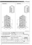
1
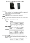
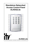
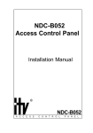
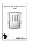
Long Range Proximity Card Reader
Installation Manual
®
l o n g
r a n g e
r e a d e r
2
Integrated Technical Vision Ltd.
http://www.itvsystems.com.ua
Contents
1. Introduction .......................................................................4
1.1 Design Change Disclaimer .................................................. 4
1.2 Reproduction Disclaimer ..................................................... 4
1.3 Trademarks ......................................................................... 4
1.4 Training and technical support ............................................ 4
2. General Characteristic ...................................................... 5
2.1 Principle of operation ........................................................... 5
2.3 Specifications ...................................................................... 5
2.2 Delivery set .......................................................................... 6
2.3 Reader layout ...................................................................... 7
3. Installation procedure ....................................................... 8
3.1 Preparation .......................................................................... 8
3.2 Installation notes ................................................................. 8
3.3 Reader mounting ................................................................. 8
3.3.1 Fixing reader with self-tapping screws ............................................... 8
3.3.2 Fixing reader with simple screws ........................................................ 8
3.3.3 Reader fixing openings ....................................................................... 9
3.3 Wiring ................................................................................ 10
3.3.1 Cable notes ....................................................................................... 10
4. Reader operation ........................................................... 10
4.1 Starting .............................................................................. 10
4.2 Reading distance ............................................................... 10
4.3 Identficator code reading ................................................... 10
4.4 Hold mode ......................................................................... 10
5. Installation notes ............................................................ 11
5.1 Power supply ..................................................................... 11
5.2 Mounting near metal surfaces ........................................... 11
5.2.1 Autotune feature ............................................................................... 11
5.3 Radio frequency interference ............................................ 11
6. Data transfer and annunciation ...................................... 12
6.1 Wiegand interface ............................................................. 12
6.1.1 Annunciation mode ........................................................................... 12
6.2 Interface RS232 ................................................................ 12
6.2.1 Packet format .................................................................................... 12
6.2.2 Transmitting data from reader .......................................................... 13
7. Limited warranty ............................................................. 14
http://www.itvsystems.com.ua
Integrated Technical Vision Ltd.
3
1. Introduction
1. Introduction
This manual covers installation and utilization of long range proximity card reader. Read
this manual carefully prior to installing the unit.
1.1 Design Change Disclaimer
Information due to design changes and product improvements in this manual is the
subject to change without notice. ITV Ltd. reserves the right to change the product design
any time that will subsequently affect the contents of this manual.
ITV Ltd. assumes no responsibility for any mistakes that can appear in the manual. The
company guarantees that this Installation Manual is up to date and corresponds with the
unit you purchase.
1.2 Reproduction Disclaimer
All rights to this document are preserved by ITV Ltd. Copying, printing and any other kind
of unauthorized reproduction of this document or a part of it is prohibited.
1.3 Trademarks
ITV® is a registered trademark of ITV Ltd.
1.4 Training and technical support
ITV Ltd. provides training in installation and utilization of the long range proximity card
reader. For detailed information about the training and discussing of our particular
requirements to the unit please contact our personnel.
It is recommended, for the staff intended for sales and installation of the long range
reader, to take instruction courses conducted by ITV company.
Technical support assumes the calls of trained specialists. End-users must apply to their
local dealers or installers. If you do not have a dealer in your area, you can contact us at
[email protected]
4
Integrated Technical Vision Ltd.
http://www.itvsystems.com.ua
2. General Characteristic
2. General Characteristic
Long range proximity card reader is a self-contained device, intended for use in various
access control systems. Reader is placed in hermetic plastic casing and can be mounted
both indoors and outdoors.
Built-in buzzer and LED provide for annunciation of reader operation. Type of annunciation
depends on programmed interface. It can be RS-232, Wiegand 26, Wiegand 37, Wiegand
42 or standard Wiegand. Interface type of the reader is programmed during manufacture
and can be easily changed in case of necessity.
The reader operates with amplitude modulation (ASK) cards and tags.
Pacemaker wearers must use caution when in close proximity to the long range
proximity card reader.
2.1 Principle of operation
Proximity identificator (card or tag) is passed to a reader. The reader reads code of
identificator and transmits it to a control panel. In a second, after the identificator is carried
out of reading range, the device is ready to read next code of identificator. Annunciation of
reader operation depends on type of programmed interface.
2.3 Specifications
Case
Material
ABS plastic
Dimensions
312 х 300 x 32 mm
Weight
2,7 kg approx.
Ambient Conditions
Oper. temp.
-35 0С ... +60 0С;
Stor. temp.
-30 0С … +80 0С;
Humidity
100% rel. at +25 0C
Electrical
Voltage
+20. . . +28 VDC
Average Current
0,35 A
Max current
up to 0,9 A
Voltage ripple
up to 500 mVp-p.
Read range
http://www.itvsystems.com.ua
up to 80 cm
Integrated Technical Vision Ltd.
5
2. General Characteristic
2.2 Delivery set
Name
6
Quantity (pcs)
Reader
1
Bushing plate
1
Installation manual
1
Self-tapping screw 4x45
1
Self-tapping screw 3,5x25
2
Screw M5x45
1
Nut M5
3
Clout 5
3
Nailing plug 5x25
2
Nailing plug 6x30
1
Integrated Technical Vision Ltd.
http://www.itvsystems.com.ua
2. General Characteristic
2.3 Reader layout
Figure 1. Layout of the reader with overall dimensions indicated
http://www.itvsystems.com.ua
Integrated Technical Vision Ltd.
7
3. Installation procedure
3. Installation procedure
3.1 Preparation
First of all determine an appropriate position for reader mounting (refer to part 3.2
“Installation notes” of this chapter). Besides, it is necessary to provide for a deepening or
a hole under reader for cable wiring.
3.2 Installation notes
1. Mount the reader at a distance more than 10cm from any metal surfaces or objects.
Influence of casual metal objects, such as nails or pipes, is compensated by autotune
function of the reader.
2. If two readers are mounted at a distance less than 2 m, reading distance of a card
may be reduced appreciably.
3.3 Reader mounting
For convenience of users there exit two variants of reader mounting, they are, fixing with
self-tapping screws and fixing with simple screws. These variants allow mounting of
reader not only on a wall, but also on turnstiles, barriers and so on.
Reader can be mounted on any flat surface with self-tapping screws.
Reader can be mounted on a surface less than 2,5mm thick with simple screws.
Self-tapping screws as well as clouts, nuts and nailing plugs are provided in delivery set.
Reader fixing openings for both mounting variants are shown on picture 2.
3.3.1 Fixing reader with self-tapping screws
A. Using bushing plate, included in delivery set, mark and then drill:
- two fixing openings 3 and 4, marked as openings for self-tapping screws, 5mm
across diameter and 35mm deep
- opening 2 for cable wiring 12mm across diameter
- opening 1 6mm across diameter
B. Pass cable through the central opening
C. Set appropriate nailing plugs in fixing openings 3 and 4.
D. Twist in self-tapping screws in two upper nailing plugs so that 3-4mm were left between
wall and screw-head
E. Set nailing plug in opening 1.
F. Mount reader on a wall and fix it with self-tapping screw on a place for safety sticker.
G. Now fix the safety sticker
H. Wire the reader to cable of access control system
3.3.2 Fixing reader with simple screws
A. Using bushing plate, included in delivery set, mark and then drill:
- two fixing openings 5 and 6, marked as openings for simple screws, 5,5mm across
diameter
- opening 2 for cable wiring 12mm across diameter
- opening 1 5,5mm across diameter
B. Pass cable through the central opening
C. Place reader on mounting surface.
D. Put on clouts on paddy screws and fasten them with nuts* on backside of mounting
surface.
E. Twist in screw M5x45 on a place for safety sticker.
F. Put on a clout on screw M5x45 and fasten it with a nut*
F. Now fix the safety sticker
G. Wire the reader to cable of access control system
* Forcing of tightening should range from 0,5 to 1,0 kg.
8
Integrated Technical Vision Ltd.
http://www.itvsystems.com.ua
3. Installation procedure
3.3.3 Reader fixing openings
Figure 2. Fixing openings of long range reader
http://www.itvsystems.com.ua
Integrated Technical Vision Ltd.
9
4. Reader operation
3.3 Wiring
Reader has 8-wire cable for connection to access control system. All wires have different
color; assignment of colors is shown in table below.
Table 1. Wires assignment
Color
Green
White
W2 / W3 / W4 / WS
Function
Data 0
Data 1
Red
Black
Brown
Orange
Blue
Yellow
+V
GND
Red Led
Green Led
B eep
Hold
R S 232
Rx
Tx
+V
GND
–
–
–
Hold
3.3.1 Cable notes
It is recommended to use AWG22 multiwire cable for connection of reader to access
control system. When using this cable the distance of 50m between reader and control
panel can be obtained.
4. Reader operation
4.1 Starting
Apply voltage to reader, and its LED starts to blink yellow and buzzer beeps, indicating
that device is powered and autotuning is taking place. In five seconds device is ready to
read codes of identificators.
4.2 Reading distance
Typical reading distance is 80 cm and depends on tag type used with it and operation
conditions.
4.3 Identficator code reading
If an identificator is presented to reader its code is read, which is indicated by built-in
buzzer and LED according to type of interface and annunciation mode (refer to section 6
“Data transfer and Annunciation”).
Repeated code reading is available in 1 second if previous identificator is carried out from
reader sensing area.
4.4 Hold mode
Reader is turned to hold mode while yellow wire is closed to ground. In this mode reader
does not read cards, which reduces current consumption of reader to 0,1A. . It is possible
to switch the hold mode by relay contacts or transistor with open drain.
Do not apply voltage to yellow wire!
10
Integrated Technical Vision Ltd.
http://www.itvsystems.com.ua
5. Installation notes
5. Installation notes
5.1 Power supply
It is recommended to use power supply 20 or 28 VDC. Average current consumption is
0,35A, and peak current is 0,9A. When in Hold mode, reader consumption is approximately 0,1A.
Note: It is not recommended to use Power Switching Supply because:
- it does not provide adequate response to rapid transient loads
- it may generate noise large enough to be transmitted to reader and interfere with
identificator code reading.
5.2 Mounting near metal surfaces
Reading distance is badly decreased, when reader is mounted in close vicinity or directly
on metal surface. Degree of reduction depends on dimensions of metal surface, type of
metal and distance from metal object to reader. Metal objects and surfaces absorb reader
radiant energy, change reader tuning and impair signal received from identificators.
Moving reader farther from metal objects and surfaces reduces energy loss.
It is necessary to limit presence of metal surfaces and objects near reader. If it is possible,
use plastic terminal box, fillings of non-magnetic dielectric, plastic brackets and so on.
5.2.1 Autotune feature
Long range reader has specific feature of autotuning its parameters. When the reader is
energized autotuning operation starts and reader parameters are tuned according to
presence of metal objects close to the device.
Each minute during reader operation tuning control takes place, and if necessary reader
parameters are tuned according to changed environment.
This feature allows compensating of decreased reading distance, when reader is mounted
on metal surface or close to metal objects, for example on metal bracket.
5.3 Radio frequency interference
Interference produced by mains transformers, electric motors, energizers, PC monitors
and other electrotechnical and electronic devices may lead to reduction of reading
distance. Hence, it is not recommended to mount reader in places with increased
electromagnetic disturbance.
http://www.itvsystems.com.ua
Integrated Technical Vision Ltd.
11
6. Data transfer and annunciation
6. Data transfer and annunciation
The reader is provided with LED indicators and built-in buzzer. LED provides for threecolored annunciation of reader operation. LED and buzzer function according to interface
type programmed.
6.1 Wiegand interface
Engaging of LED and buzzer is possible automatically or by grounding of corresponding
wire according to the table 2.
6.1.1 Annunciation mode
Types of annunciation modes are presented in table below:
х
00
01
02
03
04
05
06
07
08
Buzzer
Beep on card read
Outside control
Beep on card read
Outside control
Beep on card read
Outside control
Beep on card read
Outside control
Beep on card read
Availability to switch
ON from outside
Red LED
Normally ON, switched
Normally ON, switched
Switched OFF
Switched OFF
Normally ON, switched
Normally ON, switched
Outside control
Outside control
Green LED
Blinks at reading
Blinks at reading
Blinks at reading
Blinks at reading
Outside control
Outside control
Outside control
Outside control
Blinks at reading
Availability to switch
ON from outside
OFF at reading
OFF at reading
OFF at reading
OFF at reading
Normally ON, switched OFF at reading
Availability to switch OFF from outside
Data transfer from reader complies with the indicated standard.
6.2 Interface RS232
To control annunciation send control packet to the reader. Packets should be transmitted
with 2 400 baud rate, 8 bit data, no parity, 1 stop bit.
6.2.1 Packet format
Packet formats are represented in table below:
bit
byte 0
7
0
byte 1
–
byte 2
green
LED lit
6
1
5
0
red LED
–
blinking
green LED
–
blinking
4
0
–
–
3
1
red
LED lit
–
2
0
1
0
0
1
–
–
–
buzzer
pulsatory
–
buzzer
uninterruptedly
1 – corresponds to switching on LED or buzzer. LED blinking and buzzer pulsatory control
bits have highest priority.
Annunciation does not change until next control packet received.
12
Integrated Technical Vision Ltd.
http://www.itvsystems.com.ua
6. Data transfer and annunciation
6.2.2 Transmitting data from reader
Reader transmits data as follows:
# of byte
Destination
data:
0
1...10
11
12
23h
data
checksum
0Dh
bit
7
6
5
4
3
2
1
0
Value
0
0
1
1
x
x
x
x
Checksum: exclusive OR of low nibbles of bytes from 1 to 10, high nibble of always must
be 3h.
http://www.itvsystems.com.ua
Integrated Technical Vision Ltd.
13
7. Limited warranty
7. Limited warranty
Integrated Technical Vision Ltd warrants that for a period of eighteen months from the
date of purchase, the product shall be free of defect in materials and workmanship under
normal use and that in fulfillment of any breach of such warranty, Integrated Technical
Vision Ltd shall, at its option, repair or replace the defective equipment upon return of the
equipment to its repair depot. This warranty applies only to defects in parts and workmanship and not damages incurred in shipping or handing, or damages due to causes beyond
the control of Integrated Technical Vision Ltd such as lightning, excessive voltage,
mechanical shock, water damage, or damage arising out of abuse, alteration or improper
application of the equipment.
The foregoing warranty shall apply only to the original buyer, and is and shall be lieu of
any and all other warranties, whether expressed or implied and of all other obligations or
liabilities on the part of Integrated Technical Vision Ltd. This warranty contains the entire
warranty. Integrated Technical Vision Ltd neither assumes nor authorizes any other person
purporting to act on its behalf to modify or to change this warranty, nor to assume for it
any warranty or liability concerning this product.
In no event shall Integrated Technical Vision Ltd be liable for any direct, indirect or
consequential damages. Loss of anticipated profits, loss of time or any other losses
incurred by the buyer in connection with the purchase, installation, operation or failure of
this product.
14
Integrated Technical Vision Ltd.
http://www.itvsystems.com.ua
http://www.itvsystems.com.ua
Integrated Technical Vision Ltd.
15
210105
16
Integrated Technical Vision Ltd.
http://www.itvsystems.com.ua