1
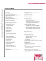
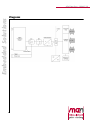
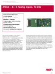
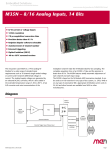
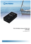
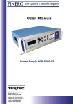
M36 Data Sheet - 2006-07-20
Embedded Solutions
M36 - 8/16 Analog Inputs
n
n
n
n
n
n
n
n
n
8/16 current or voltage inputs
16 bits resolution
10 µs acquisition/conversion time
Unipolar/bipolar software-selectable
Auto-sampling system
Communication via dual-ported RAM
External triggering
Optical isolation
On-board signal conditioning with SA-Adapter™
The M36 is a 16-bit analog input M-Module™. The
The M36 is based on the M-Module™ ANSI mezzanine
isolated supply voltages can be generated by an on-
standard. It can be used as an I/O extension in any
board DC/DC converter. Sampling on the M-Module™ is
type of bus system, i.e. CPCI, PXI™, VME or on any
completely automatic. The measured values are
type of stand-alone SBC. Appropriate M-Module™ carrier
available in a dual-ported RAM. The sequence and mode
cards in 3U, 6U and other formats are available from
of channels to be measured can also be defined in the
MEN or other manufacturers.
dual-ported RAM. Acquisition time is less than 10µs.
Input signal conditioning is done using a small
adapter.
1
®
M36 Data Sheet - 2006-07-20
Embedded Solutions
Technical Data
A/D Conversion
n 16 bits @ 10µs
n Precision: ±2 LSB, ±0.1% typ.
n Noise: ±3 LSB of mean value, delta = 0.8
n Optically isolated (500V isolation)
n Programmable gain factor of 1, 2, 4 or 8 (factor 16 by
hardware jumpering)
n Offset max. 4 LSB (25°C)
n Full-scale error max. 4 LSB (25°C)
n Software-selectable unipolar or bipolar operation
n Sample and hold
n Autoincrement of channel number
Input Signal Conditioning with AD01
n Voltage or Current Inputs
o 16 analog inputs, single-ended
o High input voltage tolerance
o Cross-talk less than 56db
o Low-pass filter 1kHz
n Voltage Measurement
o Precision: ±0.5%
o Voltage max.: ±15V
o Voltage full scale: ±10V
o Input resistance: 100 kOhm, ±10%
n Current Measurement
o Precision: ±1%
o Current max.: ±25mA
o Current full scale: ±20mA, UA = ±1.25V
o Load resistance: 62.5 Ohm, ±0.1%
Input Signal Conditioning with AD02
n Voltage or Current Inputs
o 8 analog inputs, differential
o High common mode range ±200V
o Cross-talk less than 60db
o Low-pass filter 3kHz
n Voltage Measurement
o Precision: ±0.5%
o Voltage max.: ±200V (common mode)
o Voltage full scale: ±10V
o Input resistance: 400 kOhm typ.
n Current Measurement
o Precision: ±1%
o Current max.: ±25mA
o Voltage max. to IGND: ±200V
o Input resistance: 62.5 Ohm, ±0.1%
Miscellaneous
n External trigger (isolated, rising-edge sensitive)
n External binary input
2
Peripheral Connections
n Via front panel on a shielded 25-pin D-Sub receptacle
connector
n Via carrier board (rear I/O)
M-Module™ Characteristics
n A08, D16, INTA, IDENT
Electrical Specifications
n Isolation voltage:
o 500V DC between isolated side and digital side
o 180V DC between the channels
o Voltage between the connector shield and isolated
ground is limited to 180V using a varistor; AC
coupling between connector shield and isolated ground
through 47nF capacitor
n Supply voltages/power consumption:
o +5V (4.85V..5.25V), 110mA typ. (without DC/DC
converter), 580mA (with DC/DC), 990mA (with DC/DC and
AD01)
o External supply voltages (without on-board DC/DC
converter and adapter): +15V: 14.5V..15.5V, +60mA;
-15V: 14.5V..15.5V, -32mA
n MTBF: 312,000h @ 50°C (derived from MIL-HDBK-217F)
Mechanical Specifications
n Dimensions: conforming to M-Module™ Standard
n Weight (incl. adapter): 102g
Environmental Specifications
n Temperature range (operation):
o 0..+60°C
o Industrial temperature range on request
o Airflow: min. 10m³/h
n Temperature range (storage): -40..+85°C
n Relative humidity range (operation): max. 95%
non-condensing
n Relative humidity range (storage): max. 95% non-condensing
n Altitude: -300m to + 3,000m
n Shock: 15g/11ms
n Bump: 10g/16ms
n Vibration (sinusoidal): 2g/10..150Hz
n Conformal coating on request
Safety
n PCB manufactured with a flammability rating of 94V-0 by
UL recognized manufacturers
EMC
n Tested according to EN 55022 (radio disturbance),
IEC1000-4-2 (ESD) and IEC1000-4-4 (burst) with regard to
CE conformity
®
M36 Data Sheet - 2006-07-20
Embedded Solutions
Technical Data
Software Support
n MEN Driver Interface System (MDIS™ for Windows®, Linux,
VxWorks®, QNX®, RTX, OS-9®)
3
®
M36 Data Sheet - 2006-07-20
Embedded Solutions
Diagram
4
®
M36 Data Sheet - 2006-07-20
Embedded Solutions
Ordering Information
Miscellaneous
05M000-00
M-Module™ cable, 2m, with 25-pin D-Sub
plug/housing to pig tail
05M000-17
25 mounting screw sets to fix M-Modules™ on
carrier boards
08AD01-01
Adapter for M34/M35/M36: 16 voltage inputs,
single-ended, discontinued as of December
19, 2005
08AD01-02
Adapter for M34/M35/M36: 16 current inputs,
single-ended, discontinued as of December
19, 2005
08AD01-04
Adapter for M34/M35/M36: 16 current inputs,
single-ended, temperature range:
-40..+85°C, discontinued as of December 19,
2005
08AD02-01
Adapter for M34/M35/M36: 8 voltage inputs,
differential, discontinued as of December
19, 2005
08AD02-02
Adapter for M34/M35/M36: 8 current inputs,
differential, discontinued as of December
19, 2005
08AD32-00
Adapter for M34/35/36 and M67: evaluation
card
Software: OS independent
13M036-06
MDIS4™/2004 low-level driver sources for
M36
Software: Windows
13M036-70
MDIS4™/2004 Windows® NT4/W2K/XP and XP
Embedded driver for M36
Documentation
20M000-00
M-Module™ draft specification, Rev. 3.0
20M036-00
M36 user manual
For the most up-to-date ordering information and direct
links to other data sheets and downloads, see the M36
online data sheet under » www.men.de.
5
®
M36 Data Sheet - 2006-07-20
Embedded Solutions
Contact Information
Germany
MEN Mikro Elektronik GmbH
Neuwieder Straße 5-7
90411 Nuremberg
Phone +49-911-99 33 5-0
Fax +49-911-99 33 5-901
E-mail [email protected]
www.men.de
France
MEN Mikro Elektronik SA
18, rue René Cassin
ZA de la Châtelaine
74240 Gaillard
Phone +33 (0) 450-955-312
Fax +33 (0) 450-955-211
E-mail [email protected]
www.men-france.fr
USA
MEN Micro, Inc.
PO Box 4160
Lago Vista, TX 78645-4160
Phone (512) 267-8883
Fax (512) 267-8803
E-mail [email protected]
www.menmicro.com
The date of issue stated in this data sheet refers to the Technical Data only. Changes in ordering information given herein do not affect the date of issue.
All brand or product names are trademarks or registered trademarks of their respective holders.
Information in this document has been carefully checked and is believed to be accurate as of the date of publication; however, no responsibility is assumed for
inaccuracies. MEN Mikro Elektronik accepts no liability for consequential or incidental damages arising from the use of its products and reserves the right to
make changes on the products herein without notice to improve reliability, function or design. MEN Mikro Elektronik does not assume any liability arising out of
the application or use of the products described in this document.
The products of MEN Mikro Elektronik are not suited for use in nuclear reactors and for application in medical appliances used for therapeutical purposes.
Application of MEN's products in such plants is only possible after the user has precisely specified the operation environment and after MEN Mikro Elektronik
has consequently adapted and released the product.
Copyright © 2006 MEN Mikro Elektronik GmbH. All rights reserved.
6
®