1
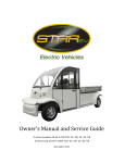
Owner’s Manual and Service Guide Enclosed Electric Shuttle Bus BN72-14-AC-D and BN72-11-AC-D Wheelchair Accessible June 2014 Thanks for buying our electric vehicle. For better use, please read through this manual before operating this vehicle to avoid any possible damage due to improper operation. Keep the manual handy after reading for future reference. Important Information: Important information is showed in following way in this manual: WARNING: Failure to follow Warning instructions could result in severe injury or death to the vehicle occupants, bystanders or persons inspecting or repairing the vehicle. CAUTION: Failure to follow Caution instructions could cause damage to the vehicle. Note: Remove the seat and backrest wrapping film to prevent seat vinyl fading. If you have to stock the vehicle for long time, also remove the seat and backrest wrapping film. 1 Table of Contents Vehicle Specifications 3 Operation 4 Important Labels 4 Functions Operational Process Safety 6 7 Maintenance 8 Battery Cleaning 8 Recharging 9 Watering 9 Specific Gravity Test 11 Open-Circuit Voltage Test 12 Installation 13 Traction/Motor 13 Troubleshooting 14 14 Speed Controller 15 Brake System 15 Lubrication General Maintenance Notes Periodical Maintenance 15 16 Storage 19 Troubleshooting 19 Electrical Diagram 25 2 Vehicle Specifications BN72-14-AC-D BN72-11-AC-D Wheelchair Accessible Passengers 14 11 + wheelchair Motor 9.5 HP AC 9.5 HP AC Battery group Controller power Maximum speed (mph) Total load capacity (lbs) Dimensions (in) Weight (lbs) Ground Clearance (in) Turing Radius (ft) Wheelbase (in) Climbing capacity (loaded) Front suspension Rear suspension Steering system Brake system Tire size Tire Pressure (psi) Wheel type 12 x 6V (72V), Trojan T-105 included 550A Curtis 1238 18 2200 12 x 6V (72V), Trojan T-105 included 550A Curtis 1238 18 2200 203 x 61 x 82 207 x 61 x 82 3130 3130 5” 5” 19.6 19.6 108” 114” 20% Independent, coil over shock Leaf spring and shock Rack and pinion 4-wheel hydraulic 155 R 12 65 20% Independent, coil over shock Leaf spring and shock Rack and pinion 4-wheel hydraulic 155 R 12 65 12” aluminum 12” aluminum 3 Operation Important Labels Please read the following labels carefully before operating the vehicle, and promptly replace any labels which become unreadable or removed. • • • Security Warning label under the dashboard Warning label under the dashboard Warning label beside the parking brake handle Functions Power key: Controls the power supply of the whole vehicle. When the key is inserted into it and turned clockwise, it will switch on the lights, horn, and the control system; when the key is turned back, the power will be switched off. Acceleration pedal: Controls the speed. It should be depressed slowly. The vehicle speeds up with the gradual stepping-down, and reaches the full speed when the pedal is stepped to the bottom. The 4 vehicle slows down when the pedal is released gradually. When the pedal is fully released, electric brake works. Service brake pedal: Decelerate the vehicle. F/R switch: This switch is a three-position button. Depressing the upper part (F) makes the vehicle move forwards while depressing the lower part (R) makes the vehicle move backwards, and the middle is neutral. NOTE: The buzzer will sound when the lower part of this button is depressed to give warning to the people around your electric vehicle. Hand-brake lever: Parks and brakes the vehicle. Steering wheel: Controls the driving direction. Light switch: Controls light system, including turning signals and headlight (includes high beam and lower beam). Wiper and horn switch: Controls the wiper and horn. Emergency stop switch: Stops the power of the whole vehicle in case of emergency. NOTE: Before you switch on the vehicle, always check the status of this switch to make sure that it is in the OFF position. Combination meter: This meter shows information including lights, speed, range, hand brake, and battery power. 5 Operational Process Starting the vehicle 1| Select F for Forward or R for Reverse from F/R Button. 2| Switch on power with key. 3| Release the handbrake lever. 4| Depress the acceleration pedal smoothly. WARNING: If you switch on Power Key first before selecting Forward or Reverse on F/R Button, the vehicle will not run. Stopping the vehicle 1| Step Service Brake Pedal to decelerate the vehicle until it stops completely and shift F/R button to Neutral position. 2| Engage the handbrake lever to park the vehicle. 3| Release the service brake. 4| Switch off all lights. 5| Switch off the power key and take out the key. Charging CAUTION: There are two different kinds of chargers for this vehicle. One is an exterior charger and the other is a built-in (on-body) charger. Before you use the charger, read the charger operation manual. Explosive hydrogen gas is produced while battery is charged. Only charge the battery in wellventilated areas. 6 Before using the charger, check if the battery charger you are using is correctly rated for your local AC electricity network. Do not disconnect the DC output cord from the battery receptacle when the charger is ON, otherwise an arc could occur which may cause an explosion. Do not open the housing of the charger. Only a qualified electrician should open the housing of the charger. The charger should be stored in safe and dry room with good ventilation. The charger should be packed properly if not used for long time. Safety The driver should have a good knowledge of the operation system of the vehicle and its features while following rules for safe operation. WARNING: Drive the vehicle off streets unless it is allowed. • • • • • • • • • • • • The vehicle cannot be overloaded, or the motor will be damaged. An overloaded vehicle can lose control and its life will be shortened. Unqualified persons are prohibited to drive the vehicle. Make sure this vehicle runs in its rated climbing ability. Don’t overtake other vehicles at crossroads, in blind areas or in other dangerous zones. Keep your entire body inside the vehicle, keep seated and holding on while the vehicle is moving. Do not start the vehicle until all occupants are securely seated. Keep your hands on the steering wheel and your eyes on the path ahead. Always back out the vehicle slowly and watch the back carefully. Avoid starting and stopping suddenly. Avoid turning the vehicle too sharply at high speeds. Always drive slowly up and down slopes. Do not make any modification or addition which may affect the capacity or safety. 7 • Children are not allowed to play in the vehicle. Children should be seated between adults and protected while the vehicle is moving. Battery Maintenance WARNING: Battery electrolyte is poisonous and dangerous, may cause severe burns, injury, etc.. Always wear protective clothing, gloves, and goggles when handling batteries, electrolyte, and charging your battery. KEEP OUT OF REACH OF CHILDREN. Cleaning The exterior of the battery, the connection wires and bolts should always be kept clean and dry. When cleaning, make sure all vent caps are tightly in place. Clean the battery top with a cloth or brush and solution of baking soda and water. When cleaning, do not allow any cleaning solution or other foreign matter to get inside the battery. This should be done every week. Clean battery terminals and the inside of cable clamps using a post and clamp cleaner. Clean terminals will have a bright metallic shine. This should be done whenever necessary. Reconnect the clamps to the terminals and thinly coat them with petroleum jelly (Vaseline) to prevent corrosion. WARNING: Before you disconnect any battery cable from any terminal on the battery, always remove the power by disconnecting the main battery cable from the controller. Checking the terminals and nuts: The connection of the battery should always be kept in good condition. Check every week on whether any battery cable terminal or nut has become loose in order to prevent any damage to terminals. Check the status of the battery cable weekly. A damaged battery cable should be replaced immediately. 8 Foreign matter: Do not place any objects on the battery and do not connect the positive pole to the negative pole. This may cause a short circuit and sparking. Recharging • As long as you use the vehicle, regardless of how long you have used it, the battery should be recharged fully on the same day. Any delay in re-charging will negatively affect the • • battery. The lead-acid battery does not develop a memory, so need not be fully discharged before recharging. If the vehicle is going to be kept unused for a long time, the battery should be fully recharged first. After that, the battery should be fully recharged every two weeks. When driving, the driver should always be aware of the drop level of the battery power from the battery power meter. Any drop means the battery power is diminishing. The driver can estimate the distance needed to be taken, and recharge the battery at a proper time in case the vehicle cannot get back to the recharging station in time for recharging. WARNING: Make sure the battery is recharged before the battery power meter shows 20% power is left inside the battery. An over-discharged battery will have a very short service life and will make recharging difficult. WARNING: During recharge, the vehicle should be parked in a well-ventilated area with the fill caps tightly secured. Keep far away from any flame and sparks to avoid any explosion or fire that could cause physical injury or damage to the property. During recharge, if the vehicle had doors, keep the doors open. Lift the seat bottom to keep the battery compartment open to the air. Watering Flooded batteries need water. More importantly, watering must be done at the right time and in the right amount or else the battery's performance and longevity suffers. Water should always be added after fully charging the battery. Prior to charging, there should be enough water to cover the plates. If the battery has been discharged partially or fully, the water level should also be above the plates. Keeping the water at the correct level after a full charge will prevent having to worry about the water level at a different state of charge. 9 It is recommended that batteries be checked once a month until you get a feel for how often you must water your batteries. Important things to remember: • • • Do not let the plates get exposed to air. This will damage (corrode) the plates. Do not fill past the water level in the filling well to the cap. This most likely will cause the battery to overflow acid, consequently losing capacity and causing corrosion. Do not use water with a high mineral content. Use distilled or de-ionized water only. WARNING: The electrolyte is a solution of acid and water so skin contact should be avoided. Watering procedure 1| Open the vent caps and look inside the fill wells. 2| Check electrolyte level; the minimum level is at the top of the plates. 3| If necessary add just enough water to cover the plates at this time. 4| Put batteries on a complete charge before adding any additional water (refer to the Charging section). 5| Once charging is completed, open the vent caps and look inside the fill wells. 6| Add water until the electrolyte level is 1/8" below the bottom of the fill well. 7| A piece of rubber can be used safely to help determine this level. 8| Clean, replace, and tighten all vent caps. CAUTION: Never add acid to a battery. Testing: Visual inspection alone is not sufficient to determine the overall health of the battery. Both open-circuit voltage and specific gravity readings can give a good indication of the battery's charge level, age, and health. Routine voltage and gravity checks will not only show the state of charge but also help spot signs of improper maintenance, such as undercharging and over-watering, and possibly even locate a bad or weak battery. The following steps outline how to properly perform routine voltage and specific gravity testing on batteries. 10 Specific Gravity Test (Flooded batteries only) 1| Do not add water at this time. 2| Fill and drain the hydrometer 2 to 4 times before pulling out a sample. 3| There should be enough sample electrolyte in the hydrometer to completely support the float. 4| Take a reading, record it, and return the electrolyte back to the cell. 5| To check another cell, repeat the 3 steps above. 6| Check all cells in the battery. 7| Replace the vent caps and wipe off any electrolyte that might have been spilled. 8| Correct the readings to 80° F: a| Add .004 to readings for every 10° above 80° F. b| Subtract .004 for every 10° below 80° F. 9| Compare the readings. 10| Check the state of charge using the table below. If any specific gravity readings register low then follow the steps below. 1| Check voltage level(s). 2| Perform equalization charge. Refer to the Equalizing section for the proper procedure. 3| Take specific gravity readings again. If any specific gravity reading still registers lower than the factory specification of 1.277+/- .007 then one or more of the following conditions may exist: 1| The battery is old and approaching the end of its life. 2| The battery was left in a state of discharge too long. 3| Electrolyte was lost due to spillage or overflow. 4| A weak or bad cell is developing. 11 5| Battery was watered excessively previous to testing. Batteries in conditions 1 - 4 should be taken to a specialist for further evaluation or retired from service. Open-Circuit Voltage Test For accurate voltage readings, batteries must remain idle (no charging, no discharging) for at least 6 hrs, preferably 24 hrs. 1| Disconnect all loads from the batteries. 2| Measure the voltage using a DC voltmeter. 3| Check the state of charge with the table below. 4| Charge the battery if it registers 0% to 70% charged. If battery registers below the Table 1 values, the following conditions may exist: 1| The battery was left in a state of discharge too long. 2| The battery has a bad cell. Batteries in these conditions should be taken to a specialist for further evaluation or retired from service. State of charge as related to specific gravity and open circuit voltage Open-Circuit Voltage Percentage of Charge Specific Gravity Corrected to 80° F 100 1.277 6.37 8.49 12.73 25.46 38.20 50.93 80 1.238 6.25 8.33 12.50 25.00 37.49 49.99 90 70 1.258 1.217 6V 6.31 6.19 12 8V 8.41 8.25 12V 12.62 12.37 24V 25.24 24.74 36V 37.85 37.12 48V 50.47 49.49 60 1.195 6.12 8.16 12.24 24.48 36.72 48.96 40 1.148 5.98 7.97 11.96 23.92 35.87 47.83 50 30 20 10 1.172 1.124 1.098 1.073 6.05 5.91 5.83 5.75 8.07 7.88 7.77 7.67 12.10 11.81 11.66 11.51 24.20 23.63 23.32 23.02 36.31 35.44 34.97 34.52 48.41 47.26 46.63 46.03 Battery Installation Tighten the battery cables to battery terminals with torque of 95 - 105 lbs. in. (10.7 - 11.9 N.M.) Make sure there is nothing else between the battery cable lug and battery terminal post. WARNING: When working with the battery, DO NOT put wrenches or any other metal objects across the battery terminals, otherwise, an arc can occur, and it may cause explosion of the battery and physical injury. Battery should be installed or replaced only by a qualified electrician. Traction/Motor Maintenance The motor is designed for use up to 4000 feet above sea level and in a temperature between -15° F and 105° F. Never keep the motor running idly. Any mud, sand, and other clinging objects should be cleaned away. Check the carbon brush every three months. To change a worn or weakened carbon brush, press spring. 13 Troubleshooting for Motor (DC Motor only) Warning: Only a qualified electrician should change and adjust the carbon brush. Symptoms All copper plates turn black The commutator turns black in a certain order and in groups The commutator turns black The brush wears out, turns colors and become broken Big sparks The brush and its wires get hot The brush is noisy Possible Causes The pressure of brush is incorrect. Short circuit in the commutator or armature coil; poor welding or disconnection between the commutators and the armature coil. The central line of the commutator deviates or its surface is not round and smooth. The motor vibrates; the clearance between the brush and its holder is too big; the clearance between the brush and commutators is too big; the mica between different commutators extrudes; the brush is made by wrong materials; the brush is the wrong type. The motor is overloaded; the commutators are not clean, round or smooth; mica or some commutators extrude; the brush is not ground properly; the brush is the wrong type; the brush is jammed in the brush holder; the brush holder become loose or vibrating; the polarity and sequence of magnetic poles is wrong. Big sparks of the brush; poor contact between brush and soft wires. The surface of the commutators is not smooth. Speed Controller Maintenance The speed controller of the vehicle is wholly imported, which adopts high frequency MOS technology to realize the control of speed, torque and brake with smoothness, silence, and high energy efficiency. 14 When the vehicle starts, the controller will inspect signals from the accelerator. If signal exceeds 20%, the HPD (protection unit in the controller) will prohibit the output of the controller. The controller will self-check when the vehicle is running. If any defect inspected, the controller will stop the vehicle to protect the operator and the vehicle. Brake System Maintenance Depress the brake pedal with a force of 65 lbs. The pedal travel shouldn’t exceed 2/3 of the full free pedal travel. The clearance for the brake plate is self-adjusted. Under a force of around 45 lbs, the parking brake handle should be fixed in one gear from 5 to 10 ratchets. When the brake handle is released completely, the brake function will stop. Inspect and change brake shoe, and add lubrication into the brake bearing periodically. Lubrication Use 901 vehicle brake oil DOT3 as brake oil. Use 1L of 85W/90GL lubrication oil for gear box. Use 1L of 90GL hypoid gear oil for the rear axle. Lubrication points: steering gears, horizontal bars, steering ball joints, and bearings. General Maintenance Notes • To avoid any damage on the brake shoe, the handbrake should be released to its bottom before staring the vehicle. 15 • • • The lubricant for rear power assembly must be applied and changed as per user’s manual. The brake system must be adjusted once every 3 months. The electricity system must be checked once every 3 months (especially main circuit) for its fastening parts and wiring connections. Meanwhile the contactor should be checked. Any • • • • • defective parts should be replaced immediately. Dust should be cleaned with low pressure air. The electric contactors easily become hot if their mutual contact is not in good condition, so special attention should be paid regularly to the electric contactors. When changing a fuse, make sure that the new fuse is right in rated current. Disconnect the positive pole from the battery when maintenance is done. Never step the accelerator hard and frequently, which may shorten the life of the controller. It is prohibited to pour any other liquids (such as battery addictives, mineral water and tap water) into the battery. Only distilled water should fill battery. Periodical Maintenance • • • • Check if the contact between contacting points of the contactor is in good condition, check for any mechanical sticking or jamming. Check if the micro switch in the accelerator can be switched on and off properly. Check if the switch for the turn signal can be switched on and off properly. Check if all the connections between the motor, the battery, and the controller are in good condition. Please use the following cleaning procedure for routine maintenance: 1| Turn the power key to OFF position. 2| Remove power by disconnecting the battery. 3| Discharge the capacitors in the controller by connecting a load (such as a contactor coil or a horn) across the controller’s B+ and B- terminals. 16 4| Remove any dirt or corrosion from the connector areas. The controller should be wiped clean with moist rag. Dry it before reconnecting the battery. The controller should not be subjected to pressured water flow from either a standard hose or a power washer. 5| Make sure the connections are tight, but do not over-tighten them. NOTE: All above checks should be performed with the power off. Above checks shall be carried out once every 3 months; after the power is turned off, the wave-filter capacitor in the controller unit should continue discharging for a few minutes more; don’t wash the electrical parts with water. You can remove dust with a brush or high–pressure air. Periodic Maintenance Chart WARNING: Make sure to turn off the power key and apply the park brake when you do the maintenance unless specified. If the owner is not familiar with the maintenance of this vehicle, the dealer should do the work. Item Descriptions Daily Weekly Monthly Quarterly Yearly Check the liquid level. Add distilled water if necessary. Charge the battery. Tighten the nut on the battery cable. Battery Check if the battery is over-discharged (the battery power meter flashing). Check the liquid density of the battery; standard density should be 1.275±0.005. Check if the battery is charged fully by using the hydrometer and checking the battery power meter. Charger Clean the surface of battery Observe the charging status, check if the charger plug becomes hot. 17 Clean the surface of the charger. Do not get any water inside the charger. Check if all terminals are tightened Controller Clean the surface of the controller. Check if the solenoid is in order, checking its touching point. Check if any water gets in. Check if it Motor properly. Do this after the power is off. becomes too hot. Check if the carbon brush should be replaced. (DC motor only) Check if the accelerator pedal works well and if it can be released freely and Check if the brake drum and shoe. automatically. Check if the hand brake functions. Check if the hose and tube for the brake liquid leaking. Check if the brake liquid inside the brake liquid tank is enough. Chassis and body Check the air pressure inside the tire, check if the tire surface is worn, and check if the nuts are tightened properly. Check if the shock absorber has any oil leaking, flat or abnormal noise. Check if there is oil leaking on the gear box and the rear end. Add the lubricant inside the wheel hub, steering system. Adjust the toe-in of the front end. Clean the body and seat. After above maintenance, drive the vehicle to check if the vehicle works properly. 18 Storage Please follow the steps below when the vehicle is stored. 1| Check the liquid level inside the battery; recharge it fully before storing the vehicle. WARNING: Charge the battery once a month if your vehicle will be stored more than one month. 2| Turn the power key to OFF position, remove the key, and store the key in a safe place. 3| Engage the handbrake. 4| Check the tire pressure to make sure its pressure is set to recommended pressure. 5| Clean the exterior of the vehicle and apply a rust inhibitor. 6| Cover the vehicle with a breathable cover and store it in a dry, safe, and well-ventilated place. 7| If you plan to store the vehicle for a longer time, check the liquid level inside the battery and recharge the battery monthly. Troubleshooting There is no settled mode to diagnose and eliminate malfunctions. During maintaining and checking, we suggest you first listen, then look and feel. Below is the diagnoses and maintenance of some common malfunctions. 19 1| The vehicle doesn’t move. Turn on power key, step on accelerator pedal, vehicle doesn’t move. Malfunction Turn on power key, voltameter has no signal Possible reason Connector(s) in circuit is loose or open Tighten or connect Battery cable(s) is loose or disconnected Tighten or change Fuse of controller or main circuit is open Power key is broken Volatmeter is broken Battery terminals connect improperly Improper operating procedure Turn on power key, voltameter has signal Controller failure Solenoid failure Accelerator failure Parking brake doesn’t loosen 2| Locking control when vehicle starts running, speed cannot be adjusted. when it starts Vehicle stops immediately after it starts Normal power at low speed, weak power at high speed Change Change Adjust Operate properly Check or change Repair or change Motor failure Malfunction Change fuse Check, repair, change Over-heat protection Vehicle runs at full speed Troubleshooting Possible reason Repair or change Loosen parking brake Check, eliminate Troubleshooting Terminals of solenoid stick together Check or repair Potentiometer failure Repair or change Controller failure Internal short of Motor Motor is assembled too tight or blocked Controller failure Accelerator Failure Repair or change Repair or change Repair or change Repair or change Controller Failure Check or change Motor Failure Accelerator Failure Change Check or change 20 Check or change 3| Vehicle cannot change direction, only runs in one direction. Malfunction Possible reason Only runs in one direction F&R switch failure Troubleshooting Change Controller Failure Change 4| Possible reason and troubleshooting for malfunctions of mechanic system. System Malfunction Possible reason Clearance of rear axle decelerating gear is too big, or the decelerating gear is Transmission system Abnormal sound when running Transmission cross shaft is worn out Gear of transmission is worn out or damaged Flange bearing is damaged Motor bearing is damaged Gear liquid is deficient or Hard to shift gear, and/or gear shift jumps in different positions Steering system broken Steering heavy empty Clutch cannot separate smoothly Gear shift wire is damaged Gear inside transmission case is worn out Orientation pin is loose Pressure of front tire is deficient Screw plug of redirector is too tight Lack of lube in redirector Toe-in is abnormal 21 Troubleshooting Adjust, change Change Change Change Change Add gear liquid Adjust Change Change Change Check the pressure and inflate Adjust Maintain/add lube Adjust Clearance of tension rod ball is too big Steering knuckle and master pin is not lubricated Steering shaft or its plastic cover is worn out Rack of redirector is worn out Screw plug of redirector is too Unstable wheels tight Toe-in is adjusted improperly Bearing of front wheel is worn out Tie rod ball and joint is worn out Redirector is loose The pressure of the two front tires is different Toe-in is too big or too small Deflected running Driving system Tightness of the left and right drum bearing of front wheels is different Brake of one wheel is too tight Spring shock absorber is abnormal Front suspension is loose Abnormal tire fray Tire pressure is abnormal Toe-in is improper Drum bearing loose U type bolt of leaf spring is loose 22 Change Add lube Change Change redirector Adjust Adjust Change Change tie rod Tighten Inflate Adjust Adjust Adjust or change Change Change Inflate Adjust Change Tighten Rim is distorted or frame is distorted Brake force of each wheel is different Overexerting accelerate or braking frequently Master cylinder and/or wheel cylinder is damaged or leaking oil Brake fluid is insufficient or Brake fail empty Air enters into oil pipe Free travel of brake pedal is too long or the clearance of arrester is too big Brake drum is worn out or distorted Master cylinder leaks oil internally Brake system The clearance of left brake drum shoe and right brake drum shoe is different Oil is on one arrester’s brake Braking deviation shoe Tire pressures are different One wheel cylinder’s piston is blocked Wheels are aligned improperly Brake drum becomes out of Braking drag round Brake pedal has no free travel 23 Tighten Adjust Alter operation Check, eliminate, change Add fluid Let air out Adjust Change Change Adjust Dispose or change Repair or change Adjust Adjust Change Adjust Clearance between brake shoe and drum is too small or releasing spring is disabled Piston of wheel cylinder is ineffective Piston of master cylinder is ineffective Parking brake is ineffective Braking noise Shoes distort Brake facing wear out Brake drum breach, scraped to uneven Adjust or change Check or change Change Change spring Change Change Change This manual tries to be as sound and elaborate as possible in literal and figurative description as well as technical description on the basis of existing data. At the same time, our company reserves the right to alter the content of this manual and this manual is subject to change without prior notice; in addition, our company has the final say on the interpretation of this manual. 24 25