1
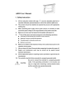
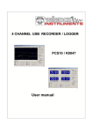
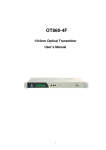
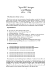
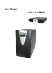
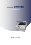
AHD31K(JK900A)User Manual
1.AHD31K(JK900A) Outside View
AHD31K(JK900A) outside structure view is as follows: (Fig.1)
Fig.1
2. Controller Installation Size
Fig.2
Page 1 of 8
3. Operation Panel Introduction
The controller display screen is a 8-digit LED digital tube, which can show operation
status, error code and parameter adjustment information.
LED display have four modes: no back tacking (Fig. 3-1);start back tacking (Fig. 3-2);
end back tacking (Fig.3-3);start and end back tacking (Fig.3-4).
NO light bright
express have
no back tacking
The first light is
bright express have
start back tacking
Fig.3-1
Fig. 3-2
The first and third
lights are bright
express have start and
end back tacking
The third light is
bright express have
end back tacking
Fig.3-3
Fig. 3-4
Start/End Back Tracking setting
Start back tracking setting: Under operator mode (see Fig.6-1),press “
” key once,
the LED will display “――”and the first light is bright(see Fig. 6-2), it express start back
tracking mode is selected. Press “
” key again will cancel the start back tracking mode (see
Fig. 4-3).
The first light is
bright express have
start back tacking
Fig 4-1
Fig.4-2
Fig.4-3
End back tracking setting:Under operator mode (see Fig.5-1), express “
NO light bright
express have
no back tacking
”
key once ,the LED will display “――”and the third light is bright (see Fig.5-2),it express end
back tracking mode is selected. Press “
” key again will cancel the end back tracking mode
Page 2 of 8
(see Fig. 5-3).
NO light bright
express have
no back tacking
The third light is
bright express have
end back tacking
Fig.5-1
Fig.5-2
Fig.5-3
Start/end back tracking setting: Under operator mode (see Fig.6-1), press “
and “
Fig.6-2),it express start/end back tracking mode is selected. Press“
and “
”key
”key,the LED will display “――”and the first and third lights are bright(see
”
”key again will cancel the start/end back tracking mode (see Fig. 6-3).
The first and third
lights are bright
express have start and
end back tacking
NO light bright
express have
no back tacking
Fig.6-1
Fig. 6-2
Fig.6-3
When there is a failure, the error code will flash. As is shown in the following figure, the
error codes are 08(Fig. 7-1)and 11(Fig. 7-2)respectively.
Fig.7-1
Fig. 7-2
Temporary speed setting: During idle mode,The user can adjust temporary speed by
key or
key.Press
key, Temporary speed can be increased Temporary speed(max.
speed can be set to Level of A setting).Press
key,The temporary speed can be decreased
(minimum speed can be set to 200rpm).The speed can be set default after resetting power.
Page 3 of 8
4.Parameter Adjustment Instructions
There are three buttons under the digital tube, one is “P”, one is “+”, the other
is“-”.Under status display, continue press “P” key, the parameter setting mode will start,
will appear, signifying A parameter. Now:
if press “+” and you can change parameter
index,there are altogether 5 parameters: A, b, C, d, and E are displayed in a circle, which are
shown as:
,
,
,
, ,they signify speed levels, up/correction needle positioning,
number of forward/ backward fixed sewing, and solenoid output setting respectively. If press
“-”you can change parameter index too,but there are altogether 5 parameters: E,d,C,b and A
are displayed in a circle, which are shown as:
,
,
,
,
.
Detailed setting shall be done as the following:
Speed Level Setting
Speed selection scope is 1-9, with 1 slowest and 9 fastest. Maximum speed is set by HMI
and the operator cannot set it. Press button“P”once, LED will display A, shown as the following
figure (Fig. 8)
Fig. 8
Press button “P”again to start speed setting, then press button “+”or“-” to choose speed
levels, press each time, the speed will be one level faster or slower. After speed setting, press
“P” to save and exit.
Up/Correction Needle Position Setting
Press “P”and press button “+”or press button “-” four times to choose LEB to display the
letter “b”, as in the following figure: (Fig. 9)
Fig. 9
Press“P” to start up/correction needle position setting, press “+”or “-”to set the parameter,
0 signifies up needle position, 1 signifies correction needle position. After setting, press button
“P” to save.
Setting number of pre-fixed sewing
After pressing button “P”, press button “+”two times or press button “-” three times,
LED will display the letter “C”, as the following figure: (Fig. 10)
Page 4 of 8
Fig.10
Press button “P” to start fixed sewing setting, and press “+”or “-” to set the number of
fixed sewing. Number of fixed sewing setting range is 0~9, 0 signifies no fixed sewing set; 1-9
signifies number of fixed sewing.
After setting, press button “P” to save.
Setting number of post-fixed sewing
After pressing button “P”, press button “+”three times or press button “-” two times.
LED will display the letter “d”, as in the following figure (Fig. 11)
Fig.11
Press button “P” to start fixed sewing setting, and press “+”or “-” to set the number of
fixed sewing. Number of fixed sewing setting range is 0—9, 0 signifies no fixed sewing set.
After setting, press button “P”to save.
Second Solenoid Output Setting
After pressing button “P” press button press button “+”four times or press button
“-”
one time. LED will display E, as in the following figure: (Fig. 12)
Fig. 12
Press button“P” to start solenoid output setting, then press button “+”or “-” to adjust
parameter setting. Parameter instructions are as follows:
0 – back tacking; 1 – thread wiping; 2 – presser foot lifting; after setting, press button “P”
to save.
In the above operation, if there is no operation for some time (5 seconds), it will go back to
stand-by status, with no changes saved.
When the machine head is lifted, but there is no action at the pedal, LED will flash all the
time till the machine head is closed, and controller works in good order.
Page 5 of 8
5.Definition of controller interface
Page 6 of 8
★
The drive ability of the LED jack:
It can drive five LED diode, which the rated current is 20mA and the rated voltage is 3V.
Recommendatory LED diode parameter as follows:
VF:Min. = 3.0V,Max. = 3.6V (test condition IF = 20mA);
Peak Forward Current:Max. = 80mA;
Continuous Forward Current :Max. = 35mA
6.Recovery processing and maintenance
error
code
meaning
solution
01
hardware overflow
02
software overflow
Turn off the system power, restart after 30 seconds, if the
controller still does not work, please replace it and inform the
manufacturer.
03
Disconnect the controller power and check if the input voltage
too low (lower than 176V). If yes, please restart the controller
system under-voltage is
when the normal voltage is resumed. If the controller still does
not work when the voltage is at normal level, please replace the
controller and inform the manufacturer.
04
over-voltage when
the machine is off
05
over-voltage in
operation
06
solenoid circuit
failure
07
electrical current
checking circuit
failure
08
09
10
11
Disconnect the controller power and check if the input voltage is
too high (higher than 264V). If yes, please restart the controller
when the normal voltage is resumed. If the controller still does
not work when the voltage is at normal level, please replace the
controller and inform the manufacturer.
Turn off the system power, check if the solenoid is connected
correctly and if it is loose or damaged. If yes, replace it in time.
Restart the system upon making sure everything is in good order.
If it still does not work, seek technical support.
Turn off the system power, restart after 30 seconds to see if it
works well. If not, try several more times. If such failure
happens frequently, seek technical support.
Disconnect the controller power, check if the motor input plug is
off, loose or damaged, or if there is something twined on the
locked motor roller machine head. After checking and correction, if the system still
does not work, please replace the controller and inform the
manufacturer.
Turn off the system power, check if the white brake resistance
on the power board is loose or dropped off, fasten it and
brake circuit failure plug
restart the system. If it still does not work, please replace the
controller and inform the manufacturer.
Check if the connecting line between control panel and
HMI communication controller is off, loose or broken, restore it and restart the
failure
system. If it still does not work, please replace the controller and
inform the manufacturer.
Check if the connection line between machine head
machine head needle synchronizer and controller is loose or not, restore it and restart
positioning failure the system. If it still does not work, please replace the controller
and inform the manufacturer.
Page 7 of 8
12
motor original angle
checking failure
Please try 2 to 3 more times after power down, if it still does not
work, please replace the controller and inform the manufacturer.
13
Motor HALL failure
Turn off the system power, check if the motor sensor plug is
loose or dropped off, restore it and restart the system. If it still
does not work, please replace the controller and inform the
manufacturer.
14
DSP Read/Write
EEPROM failure
Try another time after power down, if it still does not work,
please replace the controller and inform the manufacturer.
15
Motor over-speed
protection
Turn off the system power, turn on again in 30 seconds to see if
it works. If not, try several more times, if such failure happens
frequently, please change the controller and inform the
manufacturer.
16
Motor reversion
Turn off the system power, restart the system after 30 seconds, if
it still does not work, please replace the controller and inform
the manufacturer.
17
HMI51 Read/Write
EEPROM failure
Turn off the system power, restart the system after 30 seconds, if
it still does not work, please replace the controller and inform
the manufacturer.
18
Motor overload
Turn off the system power, restart the system after 30 seconds, if
it still does not work, please replace the controller and inform
the manufacturer.
19
Lack of oil alarm
Add oil to the needle rod, and set the P22 parameter at 4000,
resume the working time after the last oil adding; or you can
press button P to close the alarm and continue to use.
386P00336
2009.1
版本 B
Page 8 of 8