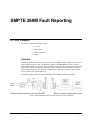
1
Ross Video Limited
DAC-8013A
SDI to Analog Component Converter
User Manual
Ross Part Number: 8013ADR-004
Issue: 01
DAC-8013A SDI to Analog Component Converter User Manual
•
•
•
Ross Part Number: 8013ADR-004
Document Issue: 01
Printed in Canada.
The information contained in this User Manual is subject to change without notice or obligation.
Copyright
© 2008 Ross Video Limited. All rights reserved.
Contents of this publication may not be reproduced in any form without the written permission of Ross
Video Limited. Reproduction or reverse engineering of copyrighted software is prohibited.
Notice
The material in this manual is furnished for informational use only. It is subject to change without
notice and should not be construed as a commitment by Ross Video Limited. Ross Video Limited
assumes no responsibility or liability for errors or inaccuracies that may appear in this manual.
Trademarks
•
•
•
is a registered trademark of Ross Video Limited.
and MLE are registered trademarks of Ross Video Limited.
Ross, ROSS,
All other product names and any registered and unregistered trademarks mentioned in this manual
are used for identification purposes only and remain the exclusive property of their respective
owners.
ROSS ®,
Important Regulatory and Safety Notices
Before using this product and any associated equipment, refer to the “Important Safety Instructions”
listed below so as to avoid personnel injury and to prevent product damage.
Products may require specific equipment, and /or installation procedures be carried out to satisfy
certain regulatory compliance requirements. Notices have been included in this publication to call
attention to these Specific requirements.
Symbol Meanings
This symbol on the equipment refers you to important operating and maintenance
(servicing) instructions within the Product Manual Documentation. Failure to heed
this information may present a major risk of damage or injury to persons or
equipment.
Warning
Caution
Notice
The symbol with the word “Warning” within the equipment manual indicates a
potentially hazardous situation, which if not avoided, could result in death or serious
injury.
The symbol with the word “Caution” within the equipment manual indicates a
potentially hazardous situation, which if not avoided, may result in minor or
moderate injury. It may also be used to alert against unsafe practices.
The symbol with the word “Notice” within the equipment manual indicates a
situation, which if not avoided, may result in major or minor equipment damage or a
situation which could place the equipment in a non-compliant operating state.
This symbol is used to alert the user that an electrical or electronic device or
assembly is susceptible to damage from an ESD event.
ESD
Susceptibility
Important Safety Instructions
Caution
This product is intended to be a component product of the RossGear 8000 series
frame. Refer to the RossGear 8000 series frame User Manual for important safety
instructions regarding the proper installation and safe operation of the frame as well
as it’s component products.
Warning
Certain parts of this equipment namely the power supply area still present a safety
hazard, with the power switch in the OFF position. To avoid electrical shock,
disconnect all A/C power cords from the chassis' rear appliance connectors before
servicing this area.
Warning
Service barriers within this product are intended to protect the operator and service
personnel from hazardous voltages. For continued safety, replace all barriers after
any servicing.
This product contains safety critical parts, which if incorrectly replaced may present
a risk of fire or electrical shock. Components contained within the product’s power
supplies and power supply area, are not intended to be customer serviced and should
be returned to the factory for repair.
To reduce the risk of fire, replacement fuses must be the same type and rating.
Only use attachments/accessories specified by the manufacturer.
EMC Notices
US FCC Part 15
This equipment has been tested and found to comply with the limits for a class A Digital device,
pursuant to part 15 of the FCC Rules. These limits are designed to provide reasonable protection
against harmful interference when the equipment is operated in a commercial environment. This
equipment generates, uses, and can radiate radio frequency energy and, if not installed and used in
accordance with the instruction manual, may cause harmful interference to radio communications.
Operation of this equipment in a residential area is likely to cause harmful interference in which case
users will be required to correct the interference at their own expense.
Changes or modifications to this equipment not expressly approved by Ross Video
Ltd. could void the user’s authority to operate this equipment.
Notice
CANADA
This Class “A” digital apparatus complies with Canadian ICES-003.
Cet appareil numerique de classe “A” est conforme à la norme NMB-003 du Canada.
EUROPE
This equipment is in compliance with the essential requirements and other relevant provisions of CE
Directive 93/68/EEC.
INTERNATIONAL
This equipment has been tested to CISPR 22:1997 along with amendments A1:2000 and A2:2002 and
found to comply with the limits for a Class A Digital device.
This is a Class A product. In domestic environments this product may cause radio
interference in which case the user may have to take adequate measures.
Notice
Maintenance/User Serviceable Parts
Routine maintenance to this RossGear product is not required. This product contains no user
serviceable parts. If the module does not appear to be working properly, please contact Technical
Support using the numbers listed under the “Contact Us” section on the last page of this manual. All
RossGear products are covered by a generous 5-year warranty and will be repaired without charge for
materials or labor within this period. See the “Warranty and Repair Policy” section in this manual for
details.
Environmental Information
The equipment that you purchased required the extraction and use of natural resources for its
production. It may contain hazardous substances that could impact health and the environment.
To avoid the potential release of those substances into the environment and to diminish the need for
the extraction of natural resources, Ross Video encourages you to use the appropriate take-back
systems. These systems will reuse or recycle most of the materials from your end-of-life equipment in
an environmentally friendly and health conscious manner.
The crossed-out wheeled bin symbol invites you to use these systems.
If you need more information on the collection, reuse, and recycling systems, please contact your local
or regional waste administration.
You can also contact Ross Video for more information on the environmental performances of our
products.
Contents
Introduction
1-1
In This Chapter .......................................................................................................................1-1
A Word of Thanks....................................................................................................1-1
Overview ..................................................................................................................1-2
Functional Block Diagram .......................................................................................1-2
Features ....................................................................................................................1-3
Documentation Terms ..............................................................................................1-3
Installation and Setup
2-1
In This Chapter .......................................................................................................................2-1
Static Discharge........................................................................................................2-1
Unpacking ................................................................................................................2-1
Board Installation .....................................................................................................2-2
BNC Labels ..............................................................................................................2-2
Cable Connections....................................................................................................2-2
User Controls
3-1
In This Chapter .......................................................................................................................3-1
Jumper Locations .....................................................................................................3-2
Input Status LED ......................................................................................................3-3
Upgrades
4-1
In This Chapter .......................................................................................................................4-1
Equipment Supplied .................................................................................................4-1
Socket and Button Locations....................................................................................4-2
Software Upgrade.....................................................................................................4-2
Confirming the Upgrade...........................................................................................4-3
SMPTE 269M Fault Reporting
5-1
In This Chapter .......................................................................................................................5-1
Overview ..................................................................................................................5-1
Jumper Setup ............................................................................................................5-2
Frame Connections...................................................................................................5-2
Details.......................................................................................................................5-2
Specifications
6-1
In This Chapter .......................................................................................................................6-1
DAC-8013A User Manual (Iss. 01)
Contents • i
Service Information
7-1
In This Chapter .......................................................................................................................7-1
Troubleshooting Checklist .......................................................................................7-1
Warranty and Repair Policy .....................................................................................7-2
Ordering Information
8-1
DAC-8013A and Related Products.........................................................................................8-1
ii • Contents
DAC-8013A User Manual (Iss. 01)
Introduction
In This Chapter
This chapter contains the following sections:
•
A Word of Thanks
•
Overview
•
Functional Block Diagram
•
Features
•
Documentation Terms
A Word of Thanks
Congratulations on choosing the Ross Video DAC-8013A SDI to Analog Component Converter.
The DAC-8013A is part of a full line of products within the RossGear Terminal Equipment family,
backed by Ross Video’s experience in engineering and design expertise since 1974.
You will be pleased at how easily your new DAC-8013A fits into your overall working environment.
Equally pleasing is the product quality, reliability and functionality. Thank you for joining the group
of worldwide satisfied Ross Video customers!
Should you have a question pertaining to the installation or operation of your DAC-8013A, please
contact us at the numbers listed on the back cover of this manual. Our technical support staff is always
available for consultation, training, or service.
DAC-8013A User Manual (Iss. 01)
Introduction • 1-1
Overview
The DAC-8013A SDI to Analog Component Converter offers an economical means of converting a
serial digital component (SDI) signal (SMPTE-259-C) to analog component format in order to feed
RGB monitors or other analog component equipment.
The DAC-8013A also functions as a serial distribution amplifier and provides one serial re-clocked
output. Input cable equalization is exceptionally good, being able to operate fault-free with 650-ft.
(200m) of 1694A cable. An LED indicator displays the input status of the card.
The ability to monitor certain signal faults and report in SMPTE 269M format is also available.
The DAC-8013A occupies one slot in the Ross DFR-8104 1RU and the DFR-8110 2RU digital rack
frames. It is also fully compatible with the Leitch* 6800 series digital rack frame.
Functional Block Diagram
Figure 1. Simplified Block Diagram of DAC-8013A Functions
*Leitch is a trademark of Leitch Technology Corporation.
1-2 • Introduction
DAC-8013A User Manual (Iss. 01)
Features
The following features make the DAC-8013A the best solution for converting SDI to analog:
•
RGB and YPrPb color spaces are supported
•
Betacam, SMPTE/EBU N10 and MII** component modes
•
Separate high-level sync or composite output
•
10-bit processing and conversion
•
Distribution amplifier with one re-clocked serial output
•
Sync may be added to the RGB signals
•
525/625 line operation
•
Fault Reporting (SMPTE 269M format)
•
Input cable equalization for 200 meters of cable
•
10 modules fit into a 2 RU frame
•
Fully compatible with Leitch 6800 series frames
•
5-year transferable warranty
Documentation Terms
The following terms are used throughout this guide:
**
•
“Frame” refers to the DFR-8104A and DFR-8110A frames that house the DAC8013A card.
•
All references to the DFR-8104A and DFR-8110A also include the
DFR-8104A-C and DFR-8110A-C versions with the cooling fan option. See the
respective User Manuals for details.
•
“Operator” and “User” both refer to the person who uses the DAC-8013A.
•
“Board” and “Card” both refer to the DAC-8013A card, including all components
and switches.
•
“System” and “Video system” refers to the mix of interconnected digital and analog
production and terminal equipment in which the DAC-8013A operates.
YPrPb color space only
DAC-8013A User Manual (Iss. 01)
Introduction • 1-3
1-4 • Introduction
DAC-8013A User Manual (Iss. 01)
Installation and Setup
In This Chapter
This chapter contains the following sections:
•
Static Discharge
•
Unpacking
•
Board Installation
•
BNC Labels
•
Cable Connections
Static Discharge
Whenever handling the DAC-8013A and other related equipment, please observe all static discharge
precautions as described in the following note.
ESD
Susceptibility
Static discharge can cause serious damage to sensitive
semiconductor devices. Avoid handling circuit boards in high
static environments such as carpeted areas, and when wearing
synthetic fiber clothing. Always exercise proper grounding
precautions when working on circuit boards and related
equipment.
Unpacking
Unpack each DAC-8013A you received from the shipping container, and check the contents against
the packing list to ensure that all items are included. If any items are missing or damaged, contact your
sales representative or Ross Video directly.
DAC-8013A User Manual (Iss. 01)
Installation and Setup • 2-1
Board Installation
Use the following procedure to install the DAC-8013A in a RossGear 8000 series digital distribution
frame:
1.
Notice
Refer to the User Manual of the RossGear 8000 series frame, to ensure that the
frame is properly installed according to instructions. If this card is to be installed in
any compatible frame other than a Ross Video product, refer to the frame
manufacturer’s manual for specific instructions.
Heat and power distribution requirements within a frame may
dictate specific slot placement of cards. Cards with many heatproducing components should be arranged to avoid areas of
excess heat build-up, particularly in frames using convectional
cooling.
2.
After selecting the desired frame installation slot, hold the DAC-8013A card by the
edges and carefully align the card-edges with the slots in the frame.
3.
Fully insert the card into the frame until the rear connection plug is properly seated.
This completes the procedure to install the DAC-8013A in a RossGear 8000 series digital distribution
frame.
BNC Labels
Affix the supplied BNC label, as per the included instructions, to the BNC area on the rear of the rack
frame.
Cable Connections
This section provides instructions for connecting cables to the DAC-8013A when mounted in
RossGear 8000 series Digital Products Frames. The DAC-8013A includes two sets of analog
component outputs, as well as SDI and Sync/CVBS outputs. It is not necessary to terminate unused
outputs. The serial input is internally terminated in 75 ohms. Refer to Figure 2 for BNC designations.
Figure 2. BNC Designations for the RossGear DFR-8110A (2RU Frame)
2-2 • Installation and Setup
DAC-8013A User Manual (Iss. 01)
User Controls
In This Chapter
This chapter contains the following sections:
•
Jumper Locations
•
Input Status LED
DAC-8013A User Manual (Iss. 01)
User Controls • 3-1
Jumper Locations
Use the following information to set up the DAC-8013A jumpers.
Figure 3. Jumper Locations
JP1 ⎯ Fault Report
JP1 – Fault Report enables or disables SMPTE 269M Fault Reporting.
Select one of the following settings:
•
EN — Enables SMPTE 269M fault reporting.
•
DIS — Disables SMPTE 269M fault reporting. This is the default setting.
Refer to Chapter 5 “SMPTE 269M Fault Reporting” for details on fault reporting.
JP2 ⎯ Output Color Space
JP2 – Output Color Space sets the output color space.
Select one of the following:
•
YPrPb — This is the default setting.
•
RGB
JP3 ⎯ Specific Format
JP3 – Specific Format sets the specific output format based on the color space selected on JP2.
YPrPb Formats
Select one of the following settings:
•
SMPTE/EBU — This is the default setting.
•
BETA
•
MII
RGB Formats
Select one of the following settings:
3-2 • User Controls
•
SMPTE/EBU — This is the default setting.
•
NTSC-RELATED (525 only)
DAC-8013A User Manual (Iss. 01)
JP4 ⎯ 525 Setup
JP4 – 525 Setup enables or disables the YPrPb setup in 525 line formats.
Select one of the following settings:
•
ON
•
OFF — This is the default setting.
JP5 ⎯ Sync On RGB
JP5 – Sync ON RGB enables or disables sync on the RGB outputs.
Select one of the following settings:
•
ON — Adds Sync to the RGB signals.
•
OFF — Sync will not be present on the RGB signals. This is the default setting.
JP6 ⎯ BNC 1 Output
JP6 – BNC 1 Output selects the output for BNC 1.
Select one of the following settings:
•
SYNC 2V — Provides 2 V p-p sync for equipment that require it.
•
SYNC 4V — Provides 4V p-p sync for equipment that require it.
•
Composite — Provides a composite signal for monitoring. The DAC-8013A uses
the required NTSC or PAL signal to match the input signal. This is the default
setting.
Input Status LED
The front edge of the card includes an LED indicator which shows the input status of the card. This
section provides information on the LED indicator of the DAC-8013A card.
Figure 4. Input Status LED Location
DAC-8013A User Manual (Iss. 01)
User Controls • 3-3
Table 1. Input Status LED Descriptions
LED
Color
Green
The input signal is within the capability of the cable equalizer and
re-clocking circuit to restore.
Red
One of the following has occurred:
• The input signal level is too low or is absent. If the signal
level is too low, the signal may still be restored correctly,
but the circuits will be working close to the limit of their
capability and reliability cannot be assured.
• The card does not recognize the line format.
• The selected output format is not supported for the input
format present.
Input Status
3-4 • User Controls
Status Description
DAC-8013A User Manual (Iss. 01)
Upgrades
In This Chapter
This chapter provides instructions to properly upgrade your DAC-8013A. To order a DAC-8013A
Upgrade Kit, contact Ross Video Technical Support using the information located in the “Contact
Us” section of this manual.
This chapter contains the following sections:
•
Equipment Supplied
•
Socket and Button Locations
•
Software Upgrade
•
Confirming the Upgrade
Equipment Supplied
•
The DAC-8013A User Manual
•
Required upgrade chip(s)
DAC-8013A User Manual (Iss. 01)
Upgrades • 4-1
Socket and Button Locations
Refer to the following diagram when upgrading the DAC-8013A card.
Figure 5. DAC-8013A Upgrade Socket and Bootload Button Locations
Software Upgrade
This procedure applies to any software upgrade you may perform on the DAC-8013A. If you are
upgrading multiple cards, repeat this procedure for each card to be upgraded.
Use the following procedure to upgrade a card:
Operating Tip
1.
With the card out of the frame, refer to Figure 5, to locate the U21 socket.
2.
If the socket is occupied, remove the chip from the socket as follows:
•
Use a tong-type IC chip removal tool (not supplied) to grab the chip by the
leadless ends and gently pry the chip out of the socket.
•
Store the chip in a labeled static-free container.
3.
Carefully remove the new chip from the packaging.
4.
Align the new chip over the socket with the keyed sides together and the legs over
the socket holes.
5.
Gently and firmly press the chip into the socket.
6.
Press the BOOTLOAD button while inserting the card into the powered frame and
wait for the upgrade to complete.
Alternately, if the frame is powered off, you can insert the card,
press the BOOTLOAD button and power on the frame.
•
When the green OK LED starts flashing, the upgrade is in progress and you
can release the BOOTLOAD button.
•
The OK LED will flash at various rates throughout the upgrade.
•
The upgrade is done when the LED stops flashing. Upgrades can take
approximately 90 seconds to complete.
7.
Confirm the upgrade following the steps in the section, “Confirming the Upgrade”.
8.
Remove the card from the frame.
9.
Repeat step 2 to remove the chip from socket U21.
This completes the procedure for upgrading a card.
4-2 • Upgrades
DAC-8013A User Manual (Iss. 01)
Confirming the Upgrade
When confirming a card upgrade, the version number of the software is reported by the LED flashing
the same number of times as the version.
When contacting Ross Video Technical Support, ensure you have the software numbers ready.
Reading Software Version Numbers
Use the following procedure to read software version numbers:
1.
Ensure the card is properly installed in the frame.
2.
Power up the card and wait until the Input Status LED is lit. Refer to Figure 6 for
the LED location.
Figure 6. DAC-8013A Input Status LED
3.
Note
Hold the BOOTLOAD button down for three seconds. The card begins to flash the
Input Status LED red in the following cycle:
•
The first set of flashes are longer and are equal to the major version
number, or M.
•
The second set of flashes are shorter and are equal to the minor revision
number, or R.
The LED repeats the cycle until the BOOTLOAD button is
released.
4.
Confirm that the displayed numbers match the upgrade version you have performed.
If the numbers do not match, contact Ross Video Technical Support.
This completes the procedure to read software version numbers.
DAC-8013A User Manual (Iss. 01)
Upgrades • 4-3
4-4 • Upgrades
DAC-8013A User Manual (Iss. 01)
SMPTE 269M Fault Reporting
In This Chapter
This chapter contains the following sections:
•
Overview
•
Jumper Setup
•
Frame Connections
•
Details
Overview
The SMPTE 269M Fault Reporting system, also known as a SMPTE “alarm”, indicates if one or more
frame modules encounter a fault or an abnormal condition. The DAC-8013A provides a jumper to
enable SMPTE-269M fault reporting. The card connects by means of an internal interface circuit to an
auxiliary telco connector on RossGear 8000 series frames. When the frame connection is interfaced
with a customer-designed system of LEDs or audible alarms, faults can be traced to a specific frame
when a card fault occurs within that frame.
The following diagram illustrates a general arrangement for SMPTE 269M alarm reporting:
Figure 7. SMPTE 269M Alarm Reporting: Internal Interface and Typical Connections
DAC-8013A User Manual (Iss. 01)
SMPTE 269M Fault Reporting • 5-1
Jumper Setup
ESD
Susceptibility
Static discharge can cause serious damage to sensitive
semiconductor devices. Avoid handling circuit boards in high
static environments such as carpeted areas, and when wearing
synthetic fiber clothing. Always exercise proper grounding
precautions when working on circuit boards and related
equipment.
Use the following procedure to set up SMPTE Fault Reporting for the DAC-8013A:
1.
To access the JP1, remove the card from the frame by pressing down the white card
ejector tab and pulling the card from the frame slot.
2.
Observing all static discharge and handling precautions, place the card with the
component side facing up on a clean and flat surface.
3.
Set JP1as follows:
•
To enable SMPTE Fault Reporting, set jumper JP1 to Enable.
•
To disable SMPTE Fault Reporting, set jumper JP1 to Disable.
This completes the procedure for setting up SMPTE Fault Reporting for the DAC-8013A.
Frame Connections
The SMPTE 269M Fault Reporting connection on RossGear 8000 series frames is provided by the
auxiliary telco connector, AUX A, for interfacing with a customer-designed alarm system.
AUX A Connector for SMPTE 269M
Fault Reporting
Figure 8. SMPTE 269M Alarm Reporting Frame Connections
Details
The fault report contacts are closed when the card detects an internal failure or a power loss condition.
The fault report will pulse closed for 1 to 2 ms every 16ms when the input signal is low, missing, or
invalid.
Some internal failures are:
• Failure of the card to initialize
• Failure in the fault reporting circuitry
• Failure to detect a valid input signal to the card
For additional information on alarm system design, refer to the SMPTE document ANSI/SMPTE
269M - 1999.
5-2 • SMPTE 269M Fault Reporting
DAC-8013A User Manual (Iss. 01)
Specifications
In This Chapter
This chapter includes the technical specifications for the DAC-8013A card.
DAC-8013A User Manual (Iss. 01)
Specifications • 6-1
Table 2. DAC-8013A Technical Specifications
Category
SDI Input
SDI Output
Component
Video Outputs
CVBS
Video Output
Sync Output
Power
Parameter
Specification
Number of Inputs
1
Standards
SMPTE 259M-C
Return Loss
>22dB to 300MHz
Equalization
Automatic, up to 200 meters
Input Impedance
75Ω
Number of Outputs
1
Standards
SMPTE 259M-C
Output Impedance
75Ω
Return Loss
>20dB to 300MHz
Signal Level
800mV +/- 10%
DC Offset
+/- 10mV
Rise and Fall Time
800pS (20-80%)
Overshoot
<5%
Number of Outputs
2 sets
Component Video Format
(525/625 Lines)
RGB: Betacam, SMPTE/EBU N10
YPrPb: Betacam, SMPTE/EBU N10, MII
Output Level (typical)
1V p-p
Output Impedance
75Ω
Output Return Loss
>45dB to 6MHz
DC Offset
+/- 10mV
Luminance Frequency Response
+/- 0.25dB to 5.5MHz
Output Quantizing
10 bits
Number of Outputs
1 (shared with Sync output)
Standard
NTSC, PAL
Output Level
1V p-p
Output Impedance
75Ω
Output Return Loss
>45dB to 6MHz
DC Offset
+/- 20mV
Number of Outputs
1 (shared with CVBS output)
Output Level
2V p-p or 4V p-p
Output Impedance
75Ω
Output Return Loss
>45dB to 6MHz
Rise and Fall Time
134 ns
Total Power Consumption
4.5W
270Mb/s 525/625 Lines
270Mb/s 525/625 Lines
Specifications are subject to change without notice.
6-2 • Specifications
DAC-8013A User Manual (Iss. 01)
Service Information
In This Chapter
This chapter contains the following sections:
•
Troubleshooting Checklist
•
Warranty and Repair Policy
Troubleshooting Checklist
Routine maintenance to this RossGear product is not required. In the event of problems with your
DAC-8013A, the following basic troubleshooting checklist may help identify the source of the
problem. If the module still does not appear to be working properly after checking all possible causes,
please contact your Ross Video products distributor, or the Ross Video Technical Support department
at the numbers listed under the “Contact Us” section at the end of this manual.
1.
Visual Review – Performing a quick visual check may reveal many problems, such
as connectors not properly seated or loose cables. Check the module, the frame, and
any associated peripheral equipment for signs of trouble.
2.
Power Check – Check the power indicator LED on the distribution frame front
panel for the presence of power. If the power LED is not illuminated, verify that the
power cable is connected to a power source and that power is available at the power
main. Confirm that the power supplies are fully seated in their slots. If the power
LED is still not illuminated, replace the power supply with one that is verified to
work.
3.
Reseat the Card in the Frame – Eject the card and reinsert it in the frame.
4.
Check Control Settings – Refer to the Installation and Operation sections of the
manual and verify all user-adjustable component settings.
5.
Input Signal Status – Verify that source equipment is operating correctly and that a
valid signal is being supplied.
6.
Output Signal Path – Verify that destination equipment is operating correctly and
receiving a valid signal.
7.
Card Exchange – Exchanging a suspect card with a card that is known to be
working correctly is an efficient method for localizing problems to individual cards.
DAC-8013A User Manual (Iss. 01)
Service Information • 7-1
Warranty and Repair Policy
The RossGear DAC-8013A is warranted to be free of any defect with respect to performance, quality,
reliability, and workmanship for a period of FIVE (5) years from the date of shipment from our
factory. In the event that your DAC-8013A proves to be defective in any way during this warranty
period, Ross Video Limited reserves the right to repair or replace this piece of equipment with a unit
of equal or superior performance characteristics.
Should you find that this DAC-8013A has failed after your warranty period has expired, we will repair
your defective product should suitable replacement components be available. You, the owner, will
bear any labor and/or part costs incurred in the repair or refurbishment of said equipment beyond the
FIVE (5) year warranty period.
In no event shall Ross Video Limited be liable for direct, indirect, special, incidental, or consequential
damages (including loss of profits) incurred by the use of this product. Implied warranties are
expressly limited to the duration of this warranty.
This DAC-8013A User Manual provides all pertinent information for the safe installation and
operation of your Product. Ross Video policy dictates that all repairs to the DAC-8013A are to be
conducted only by an authorized Ross Video Limited factory representative. Therefore, any
unauthorized attempt to repair this product, by anyone other than an authorized Ross Video Limited
factory representative, will automatically void the warranty. Please contact Ross Video Technical
Support for more information.
In Case of Problems
Should any problem arise with your DAC-8013A, please contact the Ross Video Technical Support
Department. (Contact information is supplied at the end of this publication.)
A Return Material Authorization number (RMA) will be issued to you, as well as specific shipping
instructions, should you wish our factory to repair your DAC-8013A. If required, a temporary
replacement module will be made available at a nominal charge. Any shipping costs incurred will be
the responsibility of you, the customer. All products shipped to you from Ross Video Limited will be
shipped collect.
The Ross Video Technical Support Department will continue to provide advice on any product
manufactured by Ross Video Limited, beyond the warranty period without charge, for the life of the
equipment.
7-2 • Service Information
DAC-8013A User Manual (Iss. 01)
Ordering Information
DAC-8013A and Related Products
Your DAC-8013A SDI to Analog Component Converter is a part of the RossGear family of products.
Ross Video offers a full line of RossGear terminal equipment including distribution, conversion,
monitoring, synchronizers, encoders, decoders, keyers, switchers, as well as analog audio and video
products.
Standard Equipment
•
DAC-8013A SDI to Analog Component Converter
•
8013ADR-004 SDI to Analog Component Converter User Manual
Optional Equipment
•
8013ADR-004 additional SDI to Analog Component Converter User Manual
•
DFR-8104A Digital Products Frame and Power Supply (PS-8102)
(1RU, holds 4 modules, includes 1 power supply)
•
DFR-8104A-C Digital Products Frame with Cooling Fan Module
and Power Supply (PS-8102)
(1RU, holds 4 modules, includes 1 power supply)
•
DFR-8110A Digital Products Frame and Power Supply (PS-8102)
(2RU, holds 10 modules, includes 1 power supply)
•
DFR-8110A-C Digital Products Frame with Cooling Fan Module
and Power Supply (PS-8102)
(2RU, holds 10 modules, includes 1 power supply)
DAC-8013A User Manual (Iss. 01)
Ordering Information • 8-1
Notes:
8-2 • Ordering Information
DAC-8013A User Manual (Iss. 01)
Notes:
DAC-8013A User Manual (Iss. 01)
Ordering Information • 8-3
Contact Us
Contact our friendly and professional support representatives for the following:
•
Name and address of your local dealer
•
Product information and pricing
•
Technical support
•
Upcoming trade show information
PHONE
E-MAIL
POSTAL
SERVICE
General Business Office
and Technical Support
613 • 652 • 4886
After-hours Emergency
613 • 349 • 0006
Fax
613 • 652 • 4425
General Information
[email protected]
Technical Support
[email protected]
Ross Video Limited
8 John Street,
Iroquois, Ontario, Canada
K0E 1K0
Ross Video Incorporated
P.O. Box 880,
Ogdensburg, New York, USA
13669-0880
Visit Us
Please visit us at our website for:
•
Company information
•
Related products and full product lines
•
On-line catalog
•
Trade show information
•
News
•
Testimonials