1
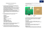
SAC6840N 2X1 Switcher USER MANUAL PRODUCT INFORMATION MODEL: SAC6840N 2X1 Switcher Version: 1.1 Modified: June 30, 2008 COMPANY NAME 北京时代奥视数码技术有限公司 Beijing Osee Digital Technology Ltd. CONTACT US Address: Room 702, Tower D, Jinyujiahua Building, No.9, 3rd Shangdi Street, Haidian District, Beijing, China Post code:100085 Tel: 8610-62968823 Fax: 8610-62977165 Http://www.osee-dig.com E-mail:[email protected] Contents Chapter 1 Introduction ............................................................................................ 1 Overview ............................................................................................................................................ 1 Features .............................................................................................................................................. 1 Module Descriptions .......................................................................................................................... 2 Back Connector .................................................................................................................................. 2 SAC6840N ................................................................................................................................. 2 Signal Flow ........................................................................................................................................ 3 Chapter 2 Installation .............................................................................................. 3 Overview ............................................................................................................................................ 3 Maximum Power Ratings for Frame .................................................................................................. 3 Unpacking the Module ....................................................................................................................... 4 Preparing the Product for Installation ........................................................................................ 4 Check the Packing List............................................................................................................... 4 Installing the Module ......................................................................................................................... 4 Install the front panel. Making the Connections ................................................................................ 5 Removing the Module ........................................................................................................................ 5 Setting Jumper.................................................................................................................................... 6 LED Indicator .................................................................................................................................... 6 GPI/GPO Interface ............................................................................................................................. 6 Chapter 3 Operation and Control ............................................................................ 7 Switches and Key ............................................................................................................................... 7 Chapter 4 Specifications ....................................................................................... 12 SDI Video Input ............................................................................................................................... 12 SDI Video Output............................................................................................................................. 12 Analog Composite Video Output ..................................................................................................... 13 Warranty for osee product ................................................................................... 14 What the warranty covers: ............................................................................................................... 14 What the warranty does not cover:................................................................................................... 14 SAC6840N 2X1 Switcher Chapter 1 Introduction Overview The SAC6840N is a SD-SDI/ASI 2X1 switcher, supports clean switching, and the switching function of which is finished based on internal circuit. When power failure happens, the signal is still through depended on the relay located at back connector, simultaneously, the setting of output is not changed. The module can work at two modes, either AUTO mode or MANUAL mode. To AUTO mode, switching happens when alarm occurs or internal status changes. To MANUAL mode, remote control panel is optional to the module. The module can be installed in 6800N series frame. Tab. 1-1 Description of SAC6840N Switcher Module Description SAC6840N 2 channels serial digital signal input, 1 channel analog reference input, 1 channel PGM output, 1 channel output of COMP or SD-SDI/ASI, ONET bus-mastering interface and GPI/GPO interface. Features The SAC6840N offers the following features: PGM OUT characters bypass function, so the signal can’t break. One channel of analog composite video signal which can pre-supervise the signal quality of input The outputs are reclocked signals Clean switching technique ensures video has no flickering, audio has no cacophony. Three control modes, AUTO mode, MANUAL mode and BYPASS mode. Auto mode based on freeze frame, black field, EDH, and audio status, such as loss, overload, parity error, and etc. 2X over-sampling and 10-bit D/A conversion ensure high-quality images. Can identify multi-format input, such as 525, 625, SDI and ASI signal Auto-equalizing technique can compensate 300m Belden 8281 cable. SAC6840N 2X1 Switcher -1- Module Descriptions Back Connector Fig.1-1 Back Connector of 6800-C2 frame SAC6840N Fig.1-2 Back Connector of SAC6840N Tab. 1-2 description of SAC6840N Back Connector Item Prescription REF IN Analog reference input IN 1 Serial digital input 1 IN 2 Serial digital input 2 PGM OUT Reclocked SDI video output (Bypass) PVW/MON OUT Reclocked SDI composite output ONET ONET bus interface GPI/GPO GPI/GPO interface SAC6840N 2X1 Switcher video output or analog -2- Signal Flow Fig. 1-3 Signal Flow of SAC6840N Chapter 2 Installation Overview The power consumption for module and the maximum power ratings that frame can sustain have to be confirmed before installing the module. In this chapter, the following topics on installation process for SAC6840N are discussed below: • • • • • Unpacking the module Setting Jumper Installing the module Making the connections Removing the module Maximum Power Ratings for Frame The maximum power ratings that different types of frames can sustain are listed in the Table 2-1 Tab. 2-1 Maximum Power Consumption Frame Maximum Voltage Redundant Power Supplies Numbers of Slots 6800N-1U 40W Yes 4 6800N-2U 60W Yes 10 SAC6840N 2X1 Switcher -3- Unpacking the Module Preparing the Product for Installation Contact your dealer right now if any items are missing. Follow the procedures below before installing the module: • • • • Check the equipment for any invisible damage that may have occurred during transit. Confirm all the items listed on the packing list have been received. Remove all the packing material including electrostatic-resistant packing. Retain these packing for future use. Check the Packing List Tab. 2-2 Packed Components Model Name Description SAC6840N SAC6840N module (1pc); back connector (1pc), and other accessories Installing the Module Caution:Static electricity may cause sensitive semiconductor out of order. Avoid installing or removing the module in the electrostatic-induced environment. Follow the following steps to install the module: Step 1 Step2 Step3 SAC6840N 2X1 Switcher -4- Step 4 Step5 Fig. 2-1 Installation of 2U Frame of 6800N Series Locate the position for back connector and insert the back connector Fasten the screw to fix the back connector. Locate the slot for module. Get the module installed in the slot, push the module slightly along the slot, press module again to confirm that the module is installed firmly and then close swivel handle. Install the front panel. Install the front panel. Making the Connections Please connect signals based on Fig. 1-2. Removing the Module Follow the following steps to remove SAC6840N module: 1. 2. Open the front part of frame. Open the swivel handle to the full. 3. First make sure the frame stands firmly, and then pull the module gently along the slot till out of frame. Install the front panel. 4. SAC6840N 2X1 Switcher -5- Setting Jumper Tab. 2-3 Description of SAC6840N Jumpers Item Description JP02 (used to choose control signal when communicating) Note: you must choose only one option RXD_INT: remote control from 6800 series frame JP03 (used to choose one signal of PVW/MON OUT in the back connector) Used to choose which one will be output, Reclocked SDI video output or analog composite output JP17 (used to choose reference signal ) FRM_REF: reference signal comes from common signal provided by 6800 series frame RXD_ONET: control signal from ONET remote control panel RXD_BOOT: reserved B_REF: reference signal is provided by Ref located at back connector JP10 ON/OFF Please set at ON if JP17 is at B_REF, While set at OFF if JP17 is at FRM_REF. LED Indicator Table 2-4 LED Indicator Function Item(color) Description POWER(green) On: Power is supplied. Auto(green) On: The device works on AUTO mode. Bypass (green) On: The device works on BYPASS mode. OUT 1 (green) On: output the first source OUT 2 (green) On: output the second source SDI (green) On: SD-SDI signal Off: ASI signal SDT (green) On: 625 Off: 525 1ER (orange) On: there is error in the first source 2ER (orange) On: there is error in the second source GPI/GPO Interface Tab. 2-5 the Definition of GPI/GPO pins Pin 1 2 3 4 5 6 7 8 9 Definition GPI0 GPI1 GPI2 GPI3 GND GPO0 GPO1 GPO2 GPO3 I/O Attribute Input Ground Output Output Output Output SAC6840N 2X1 Switcher Input Input Input -6- Tab. 2-6 GPI0 GPI1 0 0 0 1 1 0 1 1 GPI2 GPI3 0 X 1 X 0 X 1 X 0 X 1 X 0/1 X GPI control prescription Prescription Switch to the first source MANUAL mode AUTO mode Switch to the second source It has no effect on the output when the status of GPI2 changes Switch to the first source BYPASS mode Switch to the second source Invalid, no switch Note: switching can be fulfilled only when the module is in the control mode of BYPASS or MANUAL. Chapter 3 Operation and Control Switches and Key Refer to Figure 3-1 or Table 3-1(Bank 0)or Table 3-2(Bank 1)to complete control SW1 SW2 SW3 Fig. 3-1 Switches and Key Rotate SW1 at the position of 0, and select the proper Bank by SW2. Bank Selection The SW1 has two Banks Rotate the SW1 at the position of “0”. The position of “0” is always used to select Bank. Turn SW2 up or down to select Bank. 1. SW1 Mode Selection SW1 is a 16-position rotary switch, which is used to select the specific setting. The selection range is: 0, 1, 2, 3, 4, 5, 6, 7, 8, 9, A, B, C, D, E, F. 2. SW2 Mode Selection SW2 is a toggle switch, which is used to decide the concrete figure of the setting made by SW1. SW2 is a 3-position toggle switch, used to decide the concrete figure of the setting made by SW1. To keep SW2 at the position of “UP” or “DOWN”, the continuous adjustment can be achieved. SAC6840N 2X1 Switcher -7- 3. SW3 Press the SW3 to activate OSD. Tab. 3-1 SW1 Position Bank 0 Function Setting Function Options Default 0 Select Bank Bank 0,Bank 1 Bank 2,Bank 3 Bank 4 Bank 0 1 Select video standard 525 625 AUTO AUTO 2 Select control mode Bypass 1 Auto Manual Auto 3 Auto switching mode Switch to Switch back Switch back 4 Select output signal Source 2 Source 1 5 Remote Control selection Internal ONET 6 Test signal Color Bar Normal Normal 7 OSD mode Automatic On On 8 reserve 9 horizontal position of Tally 000--082 041 A Alarming display Realtime Normal Normal B Audio Mon Sel Out 1-2 Out 3-4 Out 3-4 C Control the error of de-embedding Bypass Mute Bypass D V-bit mute Enable Disable Enable E Reserve Reserve F Reserve Reserve Note : 1 To BYPASS mode, the input signal is switched directly by relay with no processing by internal circuit. SAC6840N 2X1 Switcher -8- Tab. 3-2 Bank 1 SW1 position SW1 Function Setting Function Options Default Select Bank Bank 0,Bank 1 Bank 2,Bank 3 Bank 4 Bank 0 Select Audio Group Group 1 Group 2 Group 3 Group 4 CH 1 Select the type of audio meter 1 NONE VU PEAK VU+ PEAK VU+ PEAK 3 elect the type of audio meter 2 NONE VU PEAK VU+ PEAK VU+ PEAK 4 The horizontal position of audio meter 1 000~255 8 5 The horizontal position of audio meter 2 000~255 165 6 Select audio test level -18dB -20dB -20dB 7 Freeze threshold 0~255 30 8 Freeze delay 0~255 050 Frames 9 Motion Delay 0~255 100 Frames A Black field delay 0~255 050 Frames B EDH error threshold 0~255 040 Fields C EDH error number 0~32768 D~F reserve reserve 0 1 2 SAC6840N 2X1 Switcher -9- Tab. 3-3 Bank 2 SW1 Position SW1 Function Setting Function Options Default 0 Select Bank Bank 0,Bank 1 Bank 2,Bank 3 Bank 4 Bank 0 1 Carrier En. Enable Disable Disable 2 Lock En. Enable Disable Enable 3 EDH En. Enable Disable Disable 4 EDH Err En. Enable Disable Disable 5 In1 Freeze En. Enable Disable Disable 6 In1 BB En. Enable Disable Disable 7 In1 G1 Loss En. Enable Disable Disable 8 In1 G2 Loss En. Enable Disable Disable 9 In1 G3 Loss En. Enable Disable Disable A In1 G4 Loss En. Enable Disable Disable B In1 CH1 Mute En. Enable Disable Disable C In1 CH2 Mute En. Enable Disable Disable D In1 CH3 Mute En. Enable Disable Disable E In1 CH4 Mute En. Enable Disable Disable F Reserved SAC6840N 2X1 Switcher - 10 - Tab. 3-4 Bank 3 SW1 Position Function Options Default 0 Select Bank Bank 0,Bank 1 Bank 2,Bank 3 Bank 4 Bank 0 1 In2 Freeze En. Enable Disable Disable 2 In2 BB En. Enable Disable Disable 3 In2 G1 Loss En. Enable Disable Disable 4 In2 G2 Loss En. Enable Disable Disable 5 In2 G3 Loss En. Enable Disable Disable 6 In2 G4 Loss En. Enable Disable Disable 7 In2 CH1 Mute En. Enable Disable Disable 8 In2 CH2 Mute En. Enable Disable Disable 9 In2 CH3 Mute En. Enable Disable Disable A In2 CH4 Mute En. Enable Disable Disable B~F Reserved Tab. 3-5 Bank 4 SW1 position Note: SW1 Function Setting SW1 Function Setting Function Options Default 0 Select Bank Bank 0,Bank 1 Bank 2,Bank 3 Bank 4 Bank 0 1 Auto phase 625:0—1074999 525: 0--800899 2 Auto timing Press to set 3~E Reserved Reserve F Restore the default of parameters Press to set Bank 2 and Bank 3 determine which criterion is in operation. Enable: the criterion is in operation; Disable: the criterion is invalid. SAC6840N 2X1 Switcher - 11 - Chapter 4 Specifications In this chapter, the specifications in the following subjects are introduced: SDI Video Input SDI Video Output Analog Composite Video Output SDI Video Input Table 4-1 SDI Video Input Specifications Item Parameter Standards SMPTE 259M-C, 270 Mbps, 525/625 SDI Component Impedance 75Ω termination Return Loss >18dB to 360MHz Connector BNC (IEC169-8) Equalization Auto to 30dB@270 Mbps SDI Video Output Table 4-2 SDI Video Output Specifications Item Parameter Standards SMPTE 259M-C, 270 Mbps, 525/625 SDI component Connector BNC (IEC169-8) Impedance 75Ω Return Loss >18dB to 270MHz Signal Level 800 mV ± 10% DC Offset 0 V ± 0.5 V Rise/Fall Time 400 to1500ps(20% to 80% of amplitude) Overshoot <10% Jitter <0.2 UI(740ps)Peak SAC6840N 2X1 Switcher - 12 - Analog Composite Video Output Table 4-3 Analog Composite Video Output Specifications Item Parameter Standards NTSC, PAL or PAL-M Level 1Vp-p+/-3dB Impedance 75Ω Return Loss >40 dB to 5 MHz DC Offset 0V±0.05 V Frequency Response ±0.2 dB to 5 MHz Differential Gain <1% Differential Phase <1.5° Signal to noise 75dB to 5.75MHz Note: Specifications are subject to change without notice SAC6840N 2X1 Switcher - 13 - Warranty for osee product What the warranty covers: osee warrants its products to be free from defects in material and workmanship during the warranty period of two year from purchase date. If a product proves to be defective in material or workmanship during the warranty period, osee will, at its sole option, repair or replace the product with a similar product. The replacement unit will be covered by the balance of the time remaining on the customer’s original limited warranty. No sales personnel of the seller or any other person is authorized to make any warranties other than those described above, or to extend the duration of any warranties on behalf of osee, beyond the time period describe above. This warranty is extended to the first consumer only, and proof of purchase is necessary to honor the warranty. If there is no proof of purchase provided with a warranty claim, osee reserves the right not to honor the warranty set forth above. Therefore, labor and parts may be charged to the consumer. What the warranty does not cover: 1. Any product on which the serial number has been defaced, modified or removed. 2. Damage, deterioration or malfunction resulting from: Accident, misuse, neglect, fire, water, lightning, or other acts of nature, unauthorized product modification, or failure to follow instructions supplied with the product Repair or attempted repair by anyone not authorized by osee Any damage of the product due to shipment. Removal or installation of the product. Causes external to the product, such as electric power fluctuations or failure. Use of supplies or parts not meeting osee product’s specifications. Normal wear and tear. Any other cause which does not relate to a product defect. SAC6840N 2X1 Switcher - 14 -