1
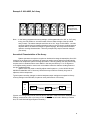
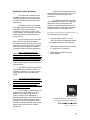
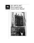
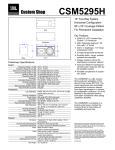
Technical Notes Volume 1, Number 25 Using HLA 4895 modules in arrays: system controller guidelines Introduction: The HLA 4895 3-way module has been designed for use in conjunction with the HLA 4897 bass enclosure and the DSC280 or DSC260 digital system controller. Hallmarks of the HLA system design include component and waveguide matching and factory-programmed settings for use with different array formats. To achieve the best results when using HLA 4895’s in arrays, knowledgeable system users will rely on careful system gain stage calibrations, an understanding of the Digital System Controller and its userconfigurable operating parameters, and practical experience gained from using the system in different types of venues. The number and placement within the array of HLA 4897 units will vary based on user preference. Understanding Setup and Use of Digital System Controllers : This application note will focus on a discussion of the different types of physical array configurations that a user is likely to encounter when using HLA 4895’s in multiple combinations. An important pre-requisite for understanding the concepts discussed here will include careful reading of the following documents: • • DSC280 (or 260) Owners Manual HLA System Owners Manual The appropriate Digital System Controller manual will familiarize the system user with both factory memory settings, and with user-configurable options. In the DSC280 manual, carefully read Section 11.0, “Xover Screen”. The HLA System Owners Manual will also enable the system user to understand how the controller is set up to properly match the input gain sensitivities of the chosen power amplifiers, and how the limiter section of the controller is set up to properly protect system components. In the HLA System Owners Manual, carefully read Section 3, “Using System Controllers” and Section 4, “Matching Transducers to Power Amplifiers”. Initial System Setup: Prior to using an HLA system in field situations, it is advisable that the system user carefully check the system controller settings to be used with the loudspeaker system. Ensure that all crossover frequencies, relative crossover bandpass settings, and limiter thresholds are properly configured. An appropriate way to do this includes the following sequence of activities: 1 1. Amp Gain Calibration: In the Xover Screen, Set the controller’s Low, Mid and High crossover bandpass settings, in dB, based on the Amp Gain of the specific power amps that will be used with the HLA system. 2. Limiter Settings: Prior to using the system controller to drive the loudspeaker system, use the Xover Utility Screen to properly set output bandpass limiter thresholds. 3. Verify Controller Signal Paths: Using electrical input signals, visually check all inputs/outputs for both left and right channels, and ensure that each band’s limiters are engaging properly. 4. Connect Controller to Amps: Complete connection of the system’s drive electronics to the power amplifiers that will be used, and visually check all power amp channels for signal present and clipping levels without speakers connected. 5. Low-Level Test: Connecting HLA loudspeakers to the power amps, supply low level audio signals for testing purposes. Confirm proper signal present in all components. 6. High-Level Test: Confirm proper system operation under full-load conditions only after above steps have been completed. 7. Custom Configurations: With growing familiarity, users can program additional custom memory settings in the Controller(s) for different HLA system applications. influence the controller settings chosen by a system user. Although factory memory settings are supplied as general guidelines, and while the system user does have a great deal of choice over the electrical signal path within the digital system controller, the 4895’s transducers each have specific design characteristics. It is important for the system owner to understand the performance parameters that are acceptable for use with the 14” and 10” loudspeakers and the high-frequency compression driver used in the HLA 4895 The low, mid and high frequency components, in coordination with their matching waveguides, are designed to provide seamless, complimentary pattern control (in both vertical and horizontal axes) at the crossover regions between each adjacent frequency bandpass, and to offer linear phase characteristics for a 3-way system. While some adjustments can be made to Sub-to-LF crossover points and bandpass gain settings, experimentation by the user should be made with care. 14” Low-frequency Unit (2254J): The 2254J is coupled together with a deep, pattern-controlled waveguide to handle the 120-297 Hz frequency band, slightly over one octave. The crossover point of 120 Hz can be adjusted downwards somewhat, to a lowest-frequency setting of 98 Hz when and if desired, only if enough low-frequency coupling is physically created by combining the 14” waveguide sections (at least 4 units) of adjacent 4895 array modules. 4895 Transducer Characteristics: While the DSC280 and DSC260 system controllers are pre-loaded with factory-recommended settings to be used with different HLA array formats, these are intended to be used as guidelines. Each system user’s choices for controller settings will influence the sonic characteristics of an HLA system. Different types of program material, various types of venues, and size and setup of the system in use may all Decreased acoustical efficiency or acoustical horn-throat distortion is likely if any attempt is made to extend the upper crossover frequency of the 2254J to beyond the factory-programmed setting of 297 Hz. 10” Mid-frequency Unit (2251J): The 2251J is carefully matched to its waveguide. When factory settings are used, system users can expect a 10dB 2 advantage in the midrange section’s Directivity Index measurements, when compared to less carefully-engineered systems. This translates into a highlyaccurate reproduction of frequencies in the vocal range, even in highly-reverberant environments. With a frequency bandpass of slightly less than two octaves, the 2251J 10” unit delivers accurate midrange reproduction over long distances without the use of distortion-inducing phase plugs as are found on many competitive systems. To meet the needs of certain system users for reproduction of specific program material, the upper crossover point may be raised somewhat, but with a loss of linear phase response. The change should be no more than one-third of an octave (to a maximum of about 1.4kHz for userdetermined special-use conditions). If changes are made in this direction, it is recommended that, in addition, e.q. compensation be added (H.F. boost on the upper end of the midrange component), and that the H.F. bandpass output drive level be boosted up to 2dB to maintain linear system response characteristics. Note that raising the crossover point between the midrange and H.F. compression driver will effectively reduce the average voltage level of the system’s high-frequency output band, since more energy will have been shifted to the midrange component. High-frequency Unit (2451SL): 1.14kHz is the optimum crossover point for audio signals entering the HLA system’s H.F. driver/waveguide. Users who attempt to set the crossover point lower than this will risk component failure. If changes are made in this critical frequency region of the system, careful bandpass-matching and e.q. compensation may be required to maintain proper system output characteristics (see previous section). The factory-programmed settings for the high frequency section of the HLA system include fairly aggressive e.q. compensation at the high end. This has been done to ensure optimum system performance in outdoor settings. System users may choose to reduce this H.F. e.q. “boost” somewhat when HLA 4895’s are used for indoor settings, particularly in rooms with well-balanced acoustics. System Controller Settings for Different Array Formats: Users may choose to make changes in system output drive levels and H.F. boost parameters as required, to optimize performance for various array configurations. Prior to making such adjustments, it is advisable to thoroughly understand the operating parameters of the Digital System Controller, the characteristics of each transducer/waveguide combination, and the acoustical characteristics of varying 4895 loudspeaker array configurations. A series of examples, showing different array formats that system users may choose to employ, is contained herewith. Using illustrations of a simple, medium-sized HLA 4895 array, graphic diagrams are coupled with a discussion of the acoustical characteristics that will typically be exhibited by each array format, along with general guidelines for controller settings and system equalization. The following examples have been included: • Example 1. – 3x2 Array with Low Frequency Coupling • Example 2. – 3x2 Array with High Frequency Coupling • Example 3. – 3x2 Array with all H.F. Horns Up • Example 4. – 3x2 Array with alternating vertical orientation (not recommended). • Example 5. – 6x1 Array • Example 6. – 2x3 Array with L.F. Coupling and Down-Tilt 3 Example 1: HLA 4895, 3x2 Array with Lows (14” Transducers) Coupled (14”) Low Frequency coupling effect Note – In the factory-programmed memory settings, as with parameters for “2x2” or “3x3” array tuning, the first number vs. second number refers to Width x Height of the HLA 4895 array or stack. The above example would thus be a “3x2” array of HLA 4895’s…three wide, two deep. Most factory-programmed memory settings in the DSC280 system controller for various array configurations assume this LF-coupled setup, per recommendations in the HLA system owners’ manual. Acoustical Characteristics of the Array: System operators can expect optimum acoustical performance from HLA arrays that are set up to couple the Low sections of the waveguides (14” loudspeaker components) together. Combining the Low-frequency horn mouths creates a larger acoustical source, and pattern control at low frequencies will be enhanced. This enables extremely accurate reproduction of low-mid frequencies (approx. 120-300 Hz) over longer distances. The greater the number of 4895 units combined together in this manner, the more noticeable this low-mid coupling effect will be. Typical system controller changes in relative bandpass output settings as compared to factory memory settings in the DSC280, for optimum sonic performance of this array: +3dB 0 LOW MID HI -3dB (System user will not typically need to make changes in relative crossover bandpass level settings, compared to a 2x2 or 3x3 array of HLA 4895’s such as is found in Memory Locations #14, 15 of the DSC280 Digital System Controller). 4 Example 2: HLA 4895, 3x2 Array with Highs (H.F. Horns) Coupled High-Frequency coupling effect Note – In the factory-programmed memory settings, such as parameters for “2x2” or “3x3” array tuning, the first number vs. second number refers to Width x Height of the HLA 4895 array or stack. The above example would thus be a “3x2” array of HLA 4895’s…three wide, two deep. However, factory-programmed settings assume Low Frequency coupling between adjacent 4895’s, as shown in Example #1 (previous page). This array example requires controller changes (see below). Acoustical Characteristics of the Array: System operators can expect increased high-frequency projection over longer distances from HLA arrays set up to couple the H.F. sections of the waveguides (compression-driver components) together as shown here. Vertically stacking the High Frequency horn mouths creates a stronger H.F. acoustical source, and high frequencies will be naturally projected over a greater distance. This can provide greater articulation and may be useful for public-address applications. The greater the number of 4895 units combined together in this manner, the more noticeable this high-frequency coupling effect will be. System users will need to carefully adjust overall system e.q. in the 2k-6kHz bandwidth. Typical system controller changes in the relative bandpass output settings as compared to factory memory settings in the DSC280, for optimum sonic performance of this array: +3dB 0 LOW MID -3dB HI (System user will typically need to make the above changes in relative crossover bandpass level settings, compared to a 2x2 or 3x3 array of HLA 4895’s such as is found in Memory Locations #14, 15 of the DSC280 Digital System Controller). 5 Example 3: HLA 4895, 3x2 Array with all High-Frequency horns on top Note: no specific array coupling advantage at any frequency Note – In the factory-programmed memory settings, such as parameters for “2x2” or “3x3” array tuning, the first number vs. second number refers to Width x Height of the HLA 4895 array or stack. The above example would thus be a “3x2” array of HLA 4895’s…three wide, two deep. However, factory-programmed settings assume Low Frequency coupling between adjacent 4895’s, as shown in Example #1 (previous page). This array example requires controller changes (see below). Acoustical Characteristics of the Array: System operators can expect relatively smooth frequency-response and coverage characteristics from HLA arrays set up as shown here, particularly for setups at indoor venues that have relatively short-throw requirements. This array format may be useful with smaller systems in “stage-stacked” situations where the Low Frequency pattern-control advantages of HLA 4895’s over long distances are less important. System users may need to carefully adjust overall system e.q. in the 90-250 Hz bandwidth due to possible anomalies in the transition from 18” (4897 bass unit) to 14” Low components. Typical system controller changes in relative bandpass output settings as compared to factory memory settings in the DSC280, for optimum sonic performance of this array: +3dB 0 LOW MID HI -3dB (System user will typically need to make the above changes in relative crossover bandpass level settings, compared to a 2x2 or 3x3 array of HLA 4895’s such as is found in Memory Locations #14, 15 of the DSC280 Digital System Controller). 6 Example 4: HLA 4895, 3x2 Array with alternating vertical orientation “Checkerboard” pattern : Not Recommended Note – In the factory-programmed memory settings, such as parameters for “2x2” or “3x3” array tuning, the first number vs. second number refers to Width x Height of the HLA 4895 array or stack. The above example would thus be a “3x2” array of HLA 4895’s…three wide, two deep. However, factory-programmed settings assume Low Frequency coupling between adjacent 4895’s, as shown in Example #1 (previous page). This array example, while not recommended, will require controller changes (see below). Acoustical Characteristics of the Array: System operators who are experiencing “beaming” or excessive reflections at certain frequencies due to architectural characteristics of particular indoor venues may find this array setup to be more satisfactory under some conditions. With this array format, users will typically experience difficulties achieving smooth system frequency response, and no acoustical coupling advantage will be available in the critical low-mid frequency range of the system. System users should anticipate careful system equalization adjustments throughout the 200-2kHz bandwidth. Typical system controller changes in relative bandpass output settings as compared to factory memory settings in the DSC280, for optimum sonic performance of this array: +3dB 0 LOW MID HI -3dB (System user will typically need to make the above changes in relative crossover bandpass level settings, compared to a 2x2 or 3x3 array of HLA 4895’s such as is found in Memory Locations #14, 15 of the DSC280 Digital System Controller). 7 Example 5: HLA 4895, 6x1 Array Note: Not Recommended for Stage Stacks Note – In the factory-programmed memory settings, such as parameters for “2x2” or “3x3” array tuning, the first number vs. second number refers to Width x Height of the HLA 4895 array or stack. The above example would thus be a “6x1” array of HLA 4895’s…six wide, one deep. While factory-programmed settings assume Low Frequency coupling between adjacent 4895’s, as shown in Example #1 (previous page), this array would not exhibit optimum coverage characteristics. This array example may require controller changes (see below). Acoustical Characteristics of the Array: System operators can expect non-optimum horizontal coverage characteristics from HLA arrays set up as shown here, particularly for setups at outdoor venues where free-field listening conditions can emphasize system coverage anomalies. That being stated, this array format may be quite useful in situations where some 4895’s in the array are tilted up 7.5 or 15 degrees to cover higher seating areas in venues such as a stadium where the audience seating areas are set up in graduated levels. System users may need to carefully adjust overall system e.q. in the 120-300 Hz and 800-2kHz bandwidths due to “line array” effects that may result from relatively long rows of adjacent, similar components. Typical system controller changes in relative bandpass output settings as compared to factory memory settings in the DSC280, for optimum sonic performance of this array: +3dB 0 LOW MID HI -3dB (System user will typically need to make the above changes in relative crossover bandpass level settings, compared to a 2x2 or 3x3 array of HLA 4895’s such as is found in Memory Locations #14, 15 of the DSC280 Digital System Controller). 8 Example 6: HLA 4895, 2x3 Flown Array with Low (14”) Coupling & Down-Tilt (14”) Low Frequency coupling effect Down-tilt waveguides for forward coverage; Ideally, connect to amp channels set -4 to –6dB lower than upper units. Note – In the factory-programmed memory settings, such as parameters for “2x2” or “3x3” array tuning, the first number vs. second number refers to Width x Height of the HLA 4895 array or stack. The above example would thus be a “2x3” array of HLA 4895’s…two wide, three deep. Optimum system use configuration. Acoustical Characteristics of the Array: This array configuration takes full advantage of the HLA system’s engineered characteristics for hanging arrays, including Low-Frequency coupling and down-tilted waveguides for covering forward seating areas. System operators can expect optimum acoustical performance from HLA arrays that are set up in this manner. Typical system controller changes in relative bandpass output settings as compared to factory memory settings in the DSC280, for optimum sonic performance of this array: +3dB 0 LOW MID HI -3dB (System user will not typically need to make changes in relative crossover bandpass level settings, compared to a 2x2 or 3x3 array of HLA 4895’s such as is found in Memory Locations #14, 15 of the DSC280 Digital System Controller). 9 Application Note Summary: The information contained herein has been compiled from various sources, including laboratory measurements under controlled conditions and actual-use field observations. Input has also been incorporated from system operators who have used JBL HLA 4895’s under a wide variety of conditions for live-music concerts, multimedia playback, public-address, and other audio applications for different types of special events. This information will be most useful to HLA system users who first become thoroughly familiar with initial system setup procedures, and who take care to calibrate their overall system signal drive paths in accordance with User Manual instructions. Upon ensuring that electronic system drive configurations fully match all factory recommendations, system operators may then choose to carefully “optimize” the controller parameters of their HLA system to match the unique needs of varying musical program styles, specific venue setups and regional tastes. System users may also benefit from the application of specialized audio system test and measurement tools like JBL SmaartPro. For additional technical information and helpful system use tips, it is suggested that system users investigate the HLA Website, accessible electronically over the World Wide Web from the JBL Professional website, located at < www.jblpro.com >. For additional useful information: • Technical Notes Volume 1, No. 23, “JBL’s HLA Series Loudspeaker System and Differential Drive Transducers” • HLA System Owners Manual, Section # 3, “Using System Controllers” • DSC280 Digital System Controller Owner Manual Note that the typical recommended ratio of 4895 array modules to 4897 Low Frequency systems is 2:1, due to the high output efficiency of the HLA 4897 bass system. User preferences for quantity and placement of 4897 units within the array, for use in conjunction with 4895’s, may vary considerably based on style of input program material and nature of the venue in which the system is used. The suitability of various factory preprogrammed controller settings for HLA system array configurations, found in memory locations in the DSC280 and DSC260 Digital System Controllers, should be evaluated by individual system users through the use of critical listening skills, in accordance with professional audio industry best practices, and particular customer preferences. JBL Professional 8500 Balboa Boulevard, P.O. Box 2200 Northridge, California 91329 U.S.A. TN VOL 1 NO 25 2/99 10